

Page 1
– 1 – – 2 – – 3 –
P/N: 1802078260010
ICS-G7526/G7528/G7826/G7828
Series
Hardware Installation Guide
First Edition, May 2011
Package Checklist
The Moxa ICS-G7526/G7528/G7826/G7828 Series industrial
rackmount switches are shipped with the followin g items. If any of
these items are missing or damaged, please contact your customer
service representative for assistance.
• ICS-G7526/G7528/G7826/G7828 switch
• RJ45 to DB9 console port cable
• 2 power cords
• Protective caps for unused ports
• 2 rackmount ears
• Documentation and software CD
• Hardware insta llation guide (pr inted)
• Warranty card
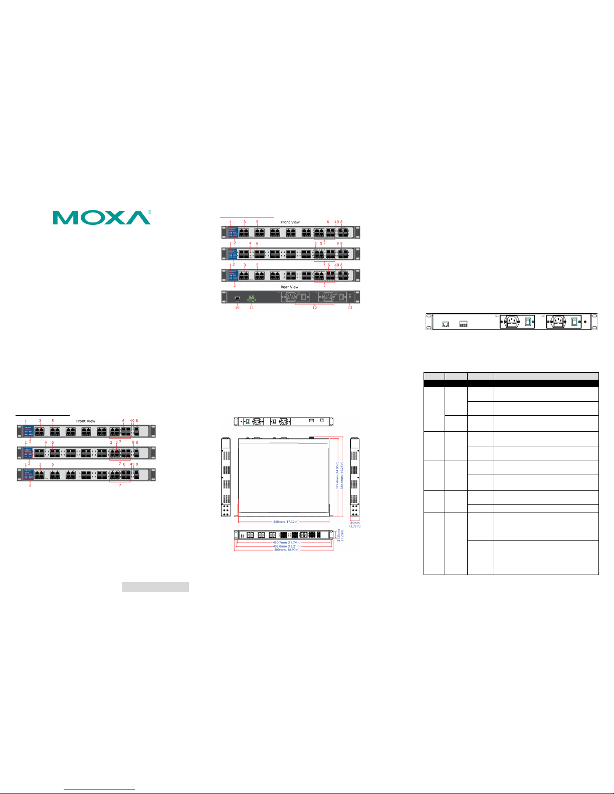
Panel Layouts
ICS-G7526/G7826
ICS-G7528/G7828
1. Model Name
2. System status LEDs
3. 10/100/1000 BaseT(X) port status LEDs
4. 100/1000Base SFP port status LEDs
5. 10/100/1000 BaseT(X) port
6. 100/1000Base S FP slot
7. 10/100/1000 BaseT(X) or 100/1000Base SFP slot combo ports
8. 10 Gigabit Ether net SFP+ slot
9. 10 Gigabit Ethernet SFP+ port status LEDs
10. Serial Console port
11. Terminal block for Relay Outpu t, Digital Inpu t
12. AC power sockets for power inputs
13. Grounding screw
Dimensions (unit = mm)
Grounding the Industrial Rackmount Switch
Grounding and wire routing help limit the effects of noise due to
electromagnetic interference (EMI). Run the ground connection
from the ground screw to the grounding surface prior to connecting
devices.
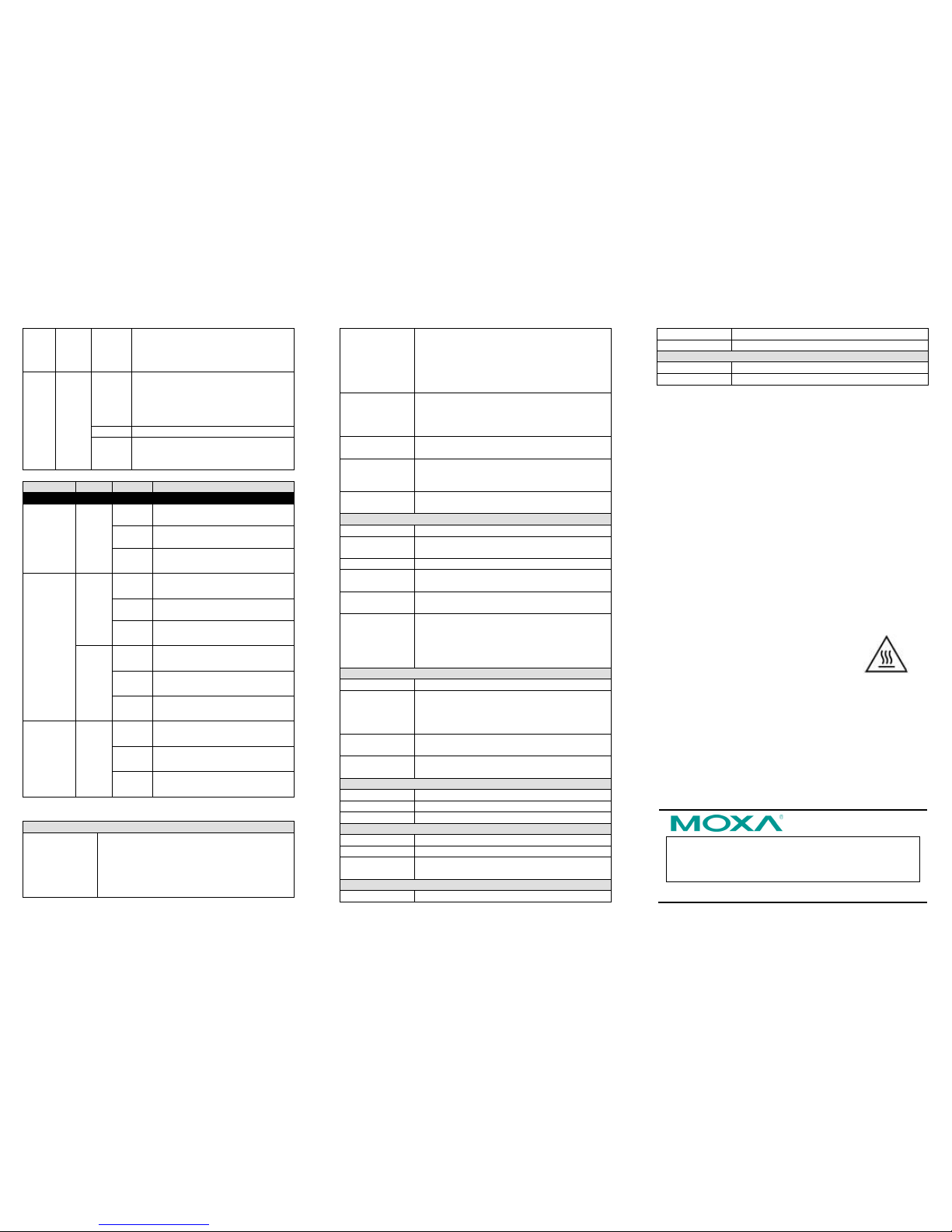
Connecting the Power Inputs
The ICS-G7526/G7528/G7826/G7828 switches support dual
redundant power supplies: Power Supply 1 (PWR1) and Power
Supply 2 (PWR2). The connections for PWR1 and PWR2 are locate d
on the rear side (shown below). Be sure to use a standard power
cord with an IEC C13 connector, which is compatible with the AC
power inlet.
LED Indicators
The front panel of the ICS-G7526/G7528/G7826/G7828 switches
contain several LED indicators. The function of each LED is
described in the table below.
LED Color State Description
System LEDs
STAT
GREEN
On
The system passed the self-diagnosis
test on boot-up and is ready to run.
Blinking
The system is undergoing the
self-diagnosis test.
RED On
The system failed self-diagnosis on
boot-up.
PWR1 AMBER
On
Power is being su pplied to the ma in
module’s power input PWR1.
Off
Power is not b eing supplied t o the main
module’s power input PWR1.
PWR2 AMBER
On
Power is being su pplied to the ma in
module’s power input PWR2.
Off
Power is not b eing supplied t o the main
module’s power input PWR2.
FAULT RED
On
The system has failed
, or is under quick
inspection.
Off The system is operating normally.
MSTR/
HEAD
GREEN
On
When the
ICS-G7526/G7528/G7826/G7828
switch is set as the Master of the Turbo
Ring, or as the Head of the Turbo Chain.
Blinking
The ICS-G7526/G7528/G7826/G7828
switch has become the Ring Master of
the Turbo Ring, or the Head of the
Turbo Chain, after the Turbo Ring or the
Turbo Chain is down.
Page 2
– 4 – – 5 – – 6 –
www.moxa.com/support
The Americas: +1-714-528-6777 (toll-free: 1-888-669-2872)
Europe: +49-89-3 70 03 99 -0
Asia-Pacific: +886-2-8919-1230
China: +86-21-5258-9955 (toll-free: 800-820-5036)
2011 Moxa Inc., All Rig hts Reserve d
Off
The ICS-G7526/G7528/G7826/G7828
switch is not the Master of this Turbo
Ring or is set as a Member of the Turbo
Chain
CPLR/
TAIL
GREEN
On
When the
ICS-G7526/G7528/G7826/G7828
switch’s
coupling function is enabled to
form a back-up
path, or when it’s set a s
the Tail of the Turbo Ch ain.
Blinking When the Turbo Chain is down
Off
When this
ICS-G7526/G7528/G7826/G7828
switch disables the coupling fun ction.
LED Color Sta te Description
Port Status LED s
10/100/
1000M (TP
ports)
GREEN On The corresponding port’s link is
active.
Blinking The corresponding port’s data is
being transmitte d.
Off The corresponding port’s link is
inactive.
100/1000M
(Fiber Optic
ports)
GREEN On The fiber optic port's 1000 Mbps
link is active.
Blinking Data is being transm itted at 1000
Mbps.
Off The fiber optic port’s 1000 Mbps
link is inactive .
AMBER On The f iber optic port's 100 Mbp s link
is active.
Blinking Data is being transmit ted at 100
Mbps.
Off The fiber optic port’s 10 0 Mbps link
is inactive.
10GbE
(Fiber Optic
ports)
GREEN On The corresponding port’s link is
active.
Blinking The corresponding port’s data is
being transmitte d.
Off The corresponding port’s link is
inactive.
Specifications
Technology
Standards IEEE 802.3 for 10BaseT
IEEE 802.3u for 100BaseT(X) and 100BaseFX
IEEE 802.3ab for 1000BaseT(X)
IEEE 802.3z for 1000BaseSX/LX/LHX/ZX
IEEE 802.3ae for 10 Gigabit Ethe rnet
IEEE 802.3x for Flow Control
IEEE 802.1D for Spanning Tree Protocol
IEEE 802.1w for Rapid STP
IEEE 802.1Q for VLAN Tagging
IEEE 802.1p for Class of Service
IEEE 802.1X for Authentication
IEEE 802.3ad for Port Trunk with LACP
Protocols IGMPv1/v2 device, GMRP, GVRP,
SNMPv1/v2c/v3, DHCP Server/Cli ent, DHCP
Option 82, BootP, TFTP, SNTP, SMTP, RARP,
RMON, HTTP, HTTPS, Telnet, SSH, Syslog
Layer 3
Switching
Static routing, RIP V1/V2, OSPF, VRRP for router
redundancy (ICS-G78
26/G7828 only)
MIB MIB-II, Etherne t-like MIB, P -BRIDGE MIB,
Q-BRIDGE MIB, Bridge MIB, RSTP MIB, RMON
MIB Groups 1, 2, 3, 9
Flow Control IEEE 802.3x flow control, back pressure flow
control
Interfa ce
Gigabit Ether net 10/100/1000BaseT(X) or 100/1000BaseSFP slot
10 Gigabit
Ethernet
10GbE SFP+ slot
Console Port RS-232 (RJ45 connector)
LED Indicators STAT, PWR1, PWR2, FAULT, MSTR/HEAD,
CPLR/TAIL
Alarm Contact 1 relay output with current carrying capacity of 2
A @ 30 VDC
Digital Inputs 1 input with the same ground, but electrically
isolated from th e electronics.
• +13 to +30V for state “1”
• -30 to +3V for state “0”
• Max.input current: 8 mA
Power Requirements
Input Voltage 110/220 VAC (85 to 264 VAC)
Input Current ICS-G7526/G7826:
Max. 0.98/0.55 A @ 110/220 VAC
ICS-G7528/G7828:
Max. 1.16/0.65 A @ 110/220 VAC
Overload Current
Protection
Present
Reverse Polarit y
Protection
Present
Physical Characteristics
Housing IP 30 protection
Dimensions 440 x 44 x 386.9 mm (17.32 x 1.73 x 15.23 in)
Installation 19” rack mounting
Environmental Limits
Operating Temp. 0 to 60°C (32 to 140°F)
Storage Temp. -40 to 85°C (-40 to 185°F)
Ambient Relative
Humidity.
5 to 95% (non-condensing)
Standards and Certifications
Safety UL 60950-1 (Pending), EN 609 50-1 (Pending)
EMI FCC Part 15 Subpart B Class A, EN 55022 Class A
Rail Traffic EN50121-4
Warranty
Warranty Period 5 years
Details See www.moxa.com/warranty
Rack Mounting Instructions
1. Elevated Operati ng Ambient: If in stalled in a close d or
multi-unit rack assembly, the operating ambient temperature
of the rack environment may be greater than room ambient.
Therefore, consideration should be given to installing the
equipment in an environment compatible with the maximum
ambient temperature (Tma) specified by the manufacturer.
2. Reduced Air Flow: Installation of the equipment in a rack
should be such that the amount of air flow required for safe
operation of the equipment is not compromised.
3. Mechanical Loading: Mounting of the equipment in the rack
should be such that a hazardous condition is not achieved due
to uneven mechanical load ing.
4. Circuit Overloading: Consideration should be given to the
connection of the equipment to the supply circuit and the
effect that overloading of the circuits might have on
overcurrent protection and supply wiring. Appropriate
consideration of equipment nameplate ratings should be used
when addressing this concern.
5. Reliable Earthing: Reliable earthing of rack -mounted
equipment should be maintained. Particular attention should
be given to supply connections other than direct connections
to the branch circuit (e.g. use of power
strips)."
Restricted Access Locations
• This equipment is intended to be used in Restricted Access
Locations, such as a computer room, with access limited t o
SERVICE PERSONAL or USERS who have been instructed on
how to handle the metal chassis of equipment that is so hot
that special protection may be needed before touching it. The
location should o nly be accessib le with a key or through a
security ident ity system.
• External metal parts of this equipment are extremely hot!!
Before touching the equipment, you must take special
precautions to protect your hands and body from serious
injury.
 Loading...