

Page 1
— 1 — — 2 — — 3—
IA240/241-LX
Quick Installation Guide
Third Edition, April 2009
1. Overview
The IA240/241 embedded computer comes with four RS-232/422/485
serial ports, a 4-ch digital input, a 4-ch digital output, dual 10/100 Mbps
Ethernet ports, PCMCIA slot for adding a wireless LAN communication
card, an SD socket interface for storage expansion, and a USB 2.0 host
port, making the IA240/241 ideal for your embedded applications.
2. Package Checklist
Before installing the IA240/241, verify that the package contains the
following items:
y 1 IA240 or IA241 embedded computer
y Wall-Mounting Kit
y DIN-Rail Mounting Kit (attached to the product casing)
y IA240/241 Quick Installation Guide (this guide)
y IA240/241 Document & Software CD
y Cross-over Ethernet cable
y CBL-RJ45M9-150: 150 cm, 8-pin RJ45 to DB9 (M) serial port cable
y CBL-RJ45F9-150: 150 cm, 8-pin RJ45 to DB9 (F) console port cable
y Universal Power Adaptor
y Product Warranty Statement
NOTE: Notify your sales representative if any of the above items are
missing or damaged.
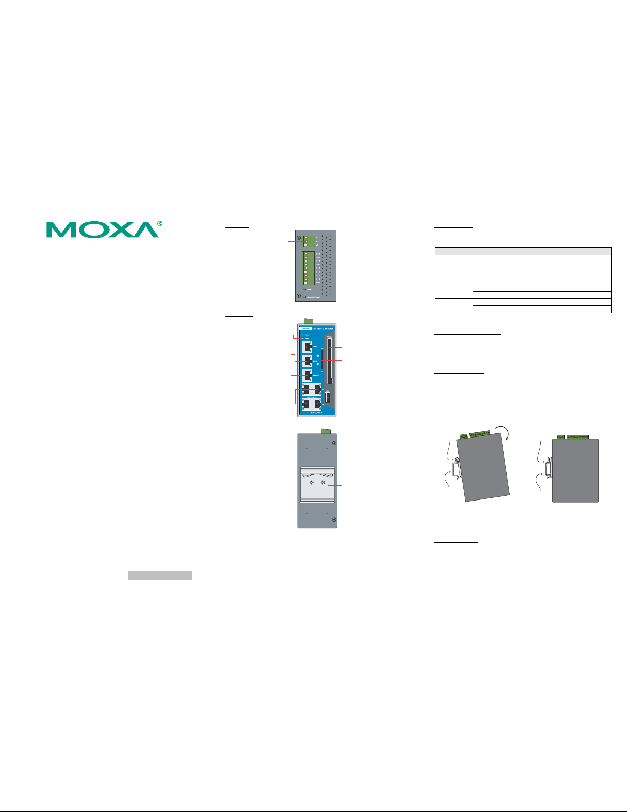
3. IA240/241 Panel Layout
The IA240 comes with four RS-232/422/485 serial ports, one RS-232
console port, dual 10/100 Mbps LAN ports, one SD socket, a 4-ch DI,
and a 4-ch DO. The IA241 supports the same functions supported by the
IA240. In addition, the IA241 comes with a PCMCIA cardbus interface
for wireless LAN card expansion. The following figures show the panel
layouts of the IA241 and IA240.
Top View
4 DI, 4 DO
Reset Button
Reset to Default
Button
12 to 48 VDC
Power Input
Front View
RS-232
Console Port
LED Indicators
Power, Ready
10/100 Mbps
Ethernet x 2
SD for Storage
Expansion
PCMCIA (IA241 only)
USB 2.0 Host
A-type Connector
RS-232/422/485 x 4
RJ45, 50 bps to 921.6 Kbps
Rear View
DIN-Rail Kit
LED Indicators
The following table describes the LED indicators located on the front
panel of the IA240/241.
LED Name LED Color LED Function
Power Red Power is on
Ready Green OS is ready and functioning normally
Orange 10 Mbps Ethernet connection
LAN 1/2
Green 100 Mbps Ethernet connection
Orange Console port is receiving RX data
Console
Green Console port is transmitting TX data
Orange Serial port 1/2/3/4 is receiving data
P1/P2/P3/P4
Green Serial port 1/2/3/4 is transmitting data
4. Installing the IA240/241
Wall or Cabinet Mounting
The IA240/241 comes with two metal brackets for attaching it to a wall
or the inside of a cabinet. Using two screws per bracket, first attach the
brackets to the rear of the IA240/241. Next, use two screws per bracket to
attach the IA240/241 to a wall or cabinet.
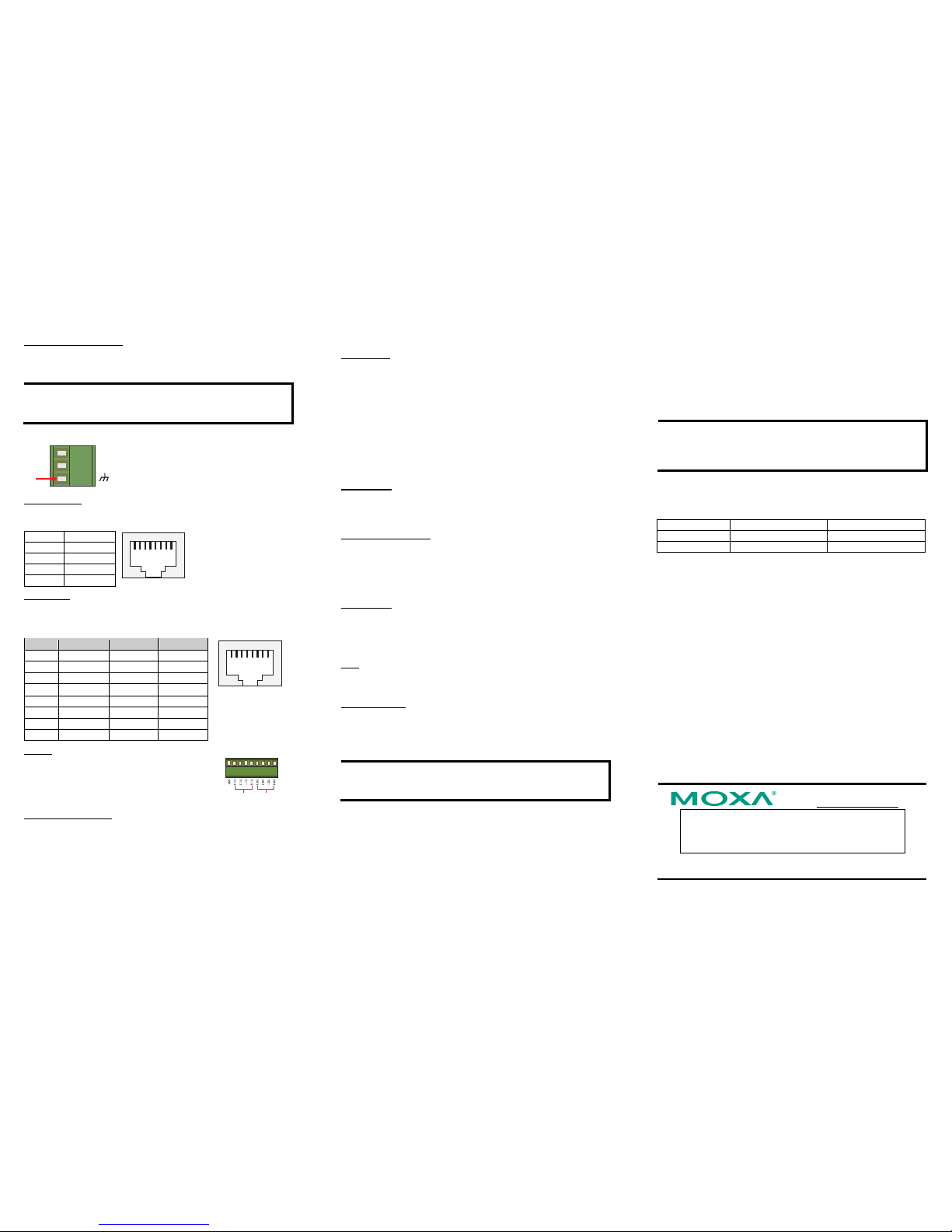
DIN-Rail Mounting
The aluminum DIN-Rail attachment plate is already attached to the
product casing. When attaching the plate to the IA240/241, make sure
that the stiff metal spring is at the top.
STEP 1: Insert the top of the
DIN-Rail into the slot just below
the stiff metal spring.
STEP 2: The DIN-Rail attachment
unit will snap into place as shown
below.
metal
spring
DIN-Rail
metal
spring
DIN-Rail
To remove the IA240/241 from the DIN-Rail, simply reverse Steps 1 and
2 above.
5. Connector Description
Power Connector
Connect the 12 to 48 VDC power line to the IA240/241’s terminal block.
If the power is properly supplied, the Power LED will light up. The OS is
ready when the Ready LED glows a solid green.
P/N: 1802002400012
Page 2
— 4 — —5— — 6—
Grounding the IA240/241
Grounding and wire routing help limit the effects of noise due to
electromagnetic interference (EMI). Run the ground connection from the
ground screw to the grounding surface prior to connecting the power.
ATTENTION
This product is intended to be mounted to a well-grounded mounting
surface, such as a metal panel.
V+
V-
SG
SG: The Shielded Ground (sometimes called
Protected Ground) contact is the bottom
contact of the 3-pin power terminal block
connector when viewed from the angle
shown here. Connect the SG wire to an
appropriate grounded metal surface.
Ethernet Ports
The two 10/100 Mbps Ethernet ports (LAN 1 and LAN 2) use RJ45
connectors.
Pin Signal
1 ETx+
2 ETx3 ERx+
6 ERx-
18
Serial Ports
The four serial ports (P1 to P4) use RJ45 connectors. Each port can be
configured by software for RS-232, RS-422, or RS-485. The pin
assignments for the ports are shown in the following table:
Pin RS-232 RS-422 RS-485
1 DSR --- --2 RTS TXD+ --3 GND GND GND
4 TXD TXD- --5 RXD RXD+ Data+
6 DCD RXD- Data7 CTS --- --8 DTR --- ---
18
DI, DO
The four Digital Input channels and four Digital
Output channels use separate terminal blocks.
4 DO 4 DI
PCMCIA (IA241 only)
The PCMCIA slot supports the CardBus (Card-32) Card standard and
16-bit (PCMCIA 2.1/JEIDA 4.2) Card standard. The slot supports +3.3V,
+5V, and +12V at a working amperage of 120 mA. Adding a wireless
LAN card is optional. The wireless LAN card provided by Moxa lets you
connect the IA240/241 to a wireless LAN, with both 802.11b and
802.11g interfaces supported.
SD Interface
Both the IA240 and IA241 come with an SD socket for storage expansion.
Moxa provides an SD flash disk for plug & play expansion. The disk
allows users to plug in a Secure Digital (SD) memory card compliant
with the SD 1.0 standard for up to 1 GB of additional memory space, or a
Secure Digital High Capacity (SDHC) memory card compliant with the
SD 2.0 standard for up to 16 GB of additional memory space. The SD
socket is located at the front side of the IA240/241. To install an SD card,
you must first remove the SD protection cover to access the socket, and
then plug the SD card into the socket directly. Remember to push in on
the SD card first if you want to remove the card.
The SD card will be mounted at /mnt/sd.
Console Port
The console port is an RJ45 RS-232 port. It is designed for serial console,
and can be connected to a V90 or GPRS modem via PPP. The pin
definitions are the same as for the four serial ports (P1 to P4).
Reset to default Button
Press the “Reset to Default” button continuously for at least 5 seconds to
load the factory default configuration. After the factory default
configuration has been loaded, the system will reboot automatically. The
Ready LED will blink on and off for the first 5 seconds, and then
maintain a steady glow once the system has rebooted.
Reset Button
Press the “Reset” button to activate the hardware reset function. You
should only use this function if the software does not function properly.
To reset a Linux system, you should reboot the operating system to avoid
deleting important data.
USB
The USB 2.0 Host port now supports a USB storage device driver. The
USB storage will be mounted at
/mnt/usbstorage.
Real Time Clock
The IA240/241’s real time clock is powered by a lithium battery. We
strongly recommend that you do not replace the lithium battery without
help from a qualified Moxa support engineer. If you need to change the
battery, contact the Moxa RMA service team.
ATTENTION
There is a risk of explosion if the battery is replaced by an incorrect type
of battery.
6. Powering on the IA240/241
To power on the IA240/241, connect the “terminal block to power jack
converter” to the IA240/241’s DC terminal block (located on the left rear
panel), and then connect the power adaptor. Note that the Shielded
Ground wire should be connected to the right most pin of the terminal
block. It takes about 30 seconds for the system to boot up. Once the
system is ready, the Ready LED will light up.
7. Connecting the IA240/241 to a PC
There are two ways to connect the IA240/241 to a PC: (1) through the
serial console port, or (2) by Telnet over the network. The COM settings
for the serial console port are: Baudrate=115200 bps, Parity=None,
Data bits=8, Stop bits =1, Flow Control=None.
ATTENTION
Remember to choose the “VT100” terminal type. Use the
CBL-RJ45F9-150 cable included with the product to connect a PC to the
IA240/241’s serial console port.
To use Telnet, you will need to know the IA240/241’s IP address and
netmask. The default LAN settings are shown below. For first-time
configuration, you may find it convenient to use a cross-over Ethernet
cable to connect directly from the PC to the IA240/241.
Default IP Address Netmask
LAN 1
192.168.3.127 255.255.255.0
LAN 2
192.168.4.127 255.255.255.0
Once the IA240/241 is powered on, the Ready LED will light up, and a
login page will open. Use the following default Login name and
Password to proceed. The defaults are:
Login: root
Password: root
8. Configuring the Ethernet Interface
If you use the console cable for first-time configuration of the Network
settings, use the following commands to edit the interfaces file:
#ifdown –a
//Disable LAN1/LAN2 interface first, before you
reconfigure the LAN settings. LAN 1 = ixp0, LAN 2= ixp1//
#vi /etc/network/interfaces
//check the LAN interface first//
After the boot setting of the LAN interface has been modified, use the
following commands to activate the LAN settings immediately:
#sync ; ifup –a
NOTE: Refer to the IA240/241 User’s Manual for information on how to
configure the WLAN interface, and for other configuration information.
Click here for online support:
www.moxa.com/support
The Americas: +1-714-528-6777 (toll-free: 1-888-669-2872)
Europe: +49-89-3 70 03 99-0
Asia-Pacific: +886-2-8919-1 230
China: +86-21-5258-9955 (toll-free: 800-820-5036)
© 2008 Moxa Inc., all rights reserved.
Reproduction without permission is proh ibited.
 Loading...