

Moxa Technologies EXPC-1519, EXPC-1519-C1-S1-T, EXPC-1519-C7-S2-T, EXPC-1519-C7-S1-T, EXPC-1519-C1-S3-T Quick Installation Manual
...Page 1

P/N: 1802015190010
*1802015190010*
EXPC-1519 Series
Quick Installation Guide
Edition 1.0, September 2015
Technical Support Contact Information
www.moxa.com/support
Moxa Americas:
Toll
-free: 1-888-669-2872
Tel:
1-714-528-6777
Fax:
1-714-528-6778
Moxa China (Shanghai office):
Toll
-free: 800-820-5036
Tel:
+86-21-5258-9955
Fax:
+86-21-5258-5505
Moxa Europe:
Tel:
+49-89-3 70 03 99-0
Fax:
+49-89-3 70 03 99-99
Moxa Asia-Pacific:
Tel:
+886-2-8919-1230
Fax:
+886-2-8919-1231
Moxa India:
Tel:
+91-80-4172-9088
Fax:
+91-80-4132-1045
2015 Moxa Inc. All rights reserved.
Page 2
- 2 -
Overview
The EXPC-1519 series Zone 2 panel computers feature advanced 3rd
generation Intel® Core™ processors—i7-3555LE and Celeron
1047UE—with 4 GB of system memory expandable to 16 GB, delivering a
reliable, high-performance platform of wide versat ility for use in harsh oi l
and gas environments.
Package Checklist
Before installing the EXPC-1519, verify that the package contains the
following it e ms for your model.
Model
Package Checklist
EXPC-1519-C1-S1-T
EXPC-1519-C7-S1-T
EXPC-1519-C1-S2-T
EXPC-1519-C7-S2-T
• 1 EXPC-1519 panel computer
• HDD/SSD installation kit
• 1 2-pin terminal block for DC power input
• 1 3-pin terminal block for AC power input
• Quick installation guide
• Documentation & software DVD
• Warranty card
EXPC-1519-C1-S3-T
EXPC-1519-C7-S3-T
• 1 EXPC-1519 panel computer
• HDD/SSD installation kit
• USB female connector installation kit
• RJ45 female connector installation kit
• DC power installation kit
• AC power installation kit
• Quick installation guide
• Documentation & software DVD
• Warranty card
NOTE
Please notify your sales representative if any of the above items
are missing or damaged.
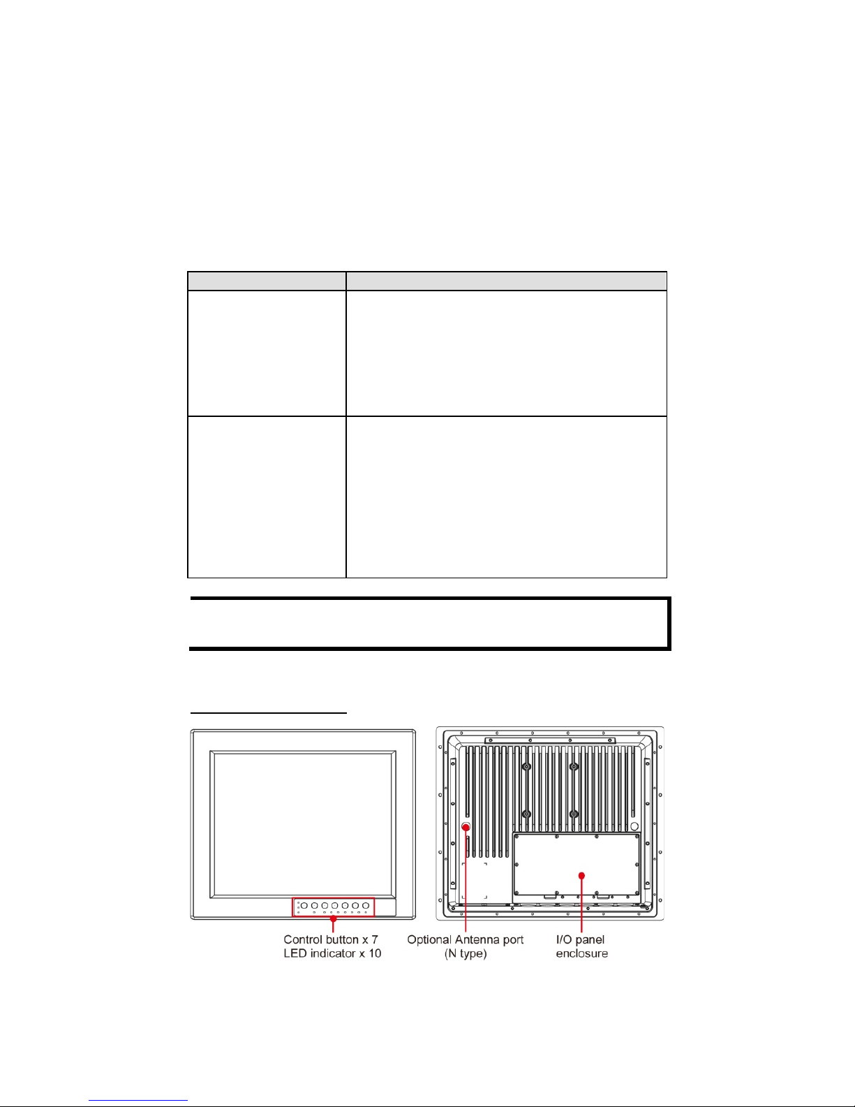
Hardware Overview
Front and Rear Views
Page 3
- 3 -
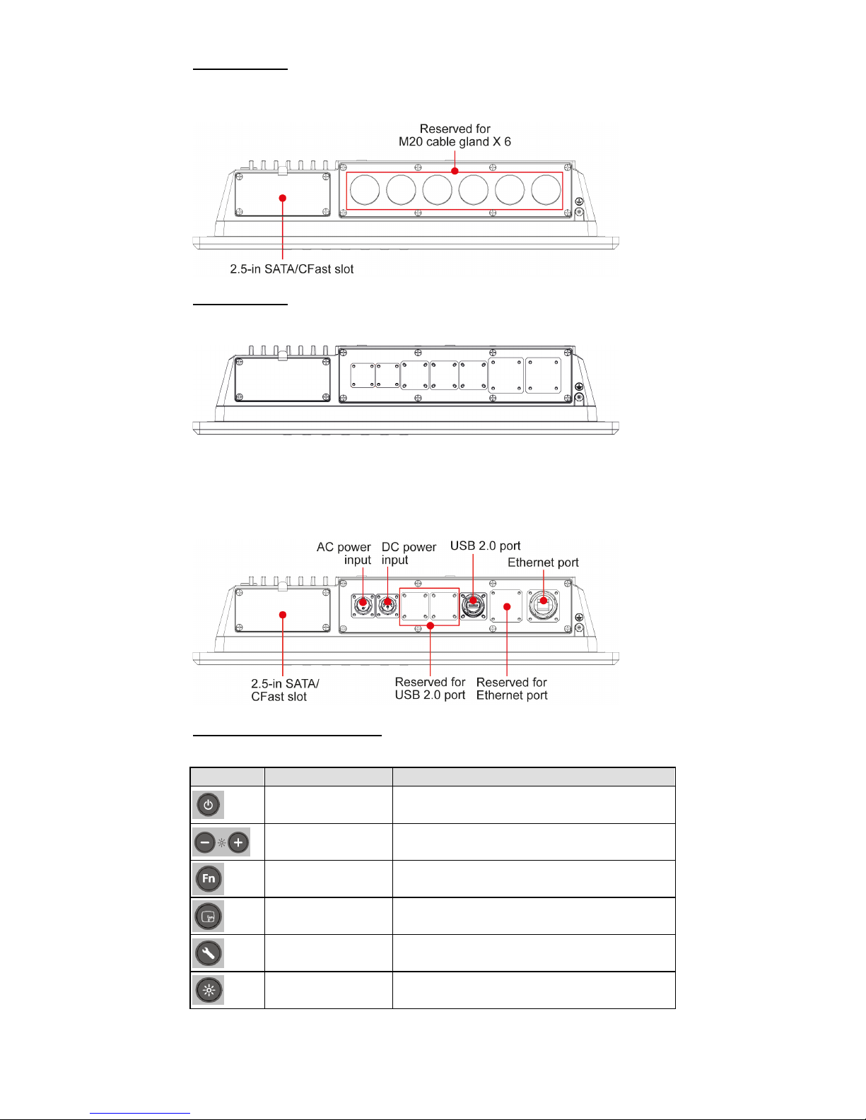
Bottom View
Applies to: EXPC-1519-C1-S1-T, EXPC-1519-C7-S1-T,
EXPC-1519-C1-S2-T, EXPC-1519-C7-S2-T
Bottom View
Applies to: EXPC-1519-C1-S3-T, EXPC-1519-C7-S3-T
The accessories provided with the product include an AC power connector,
DC power connector, USB connector, and RJ45 connector. Install the
items required for your own application. Th e following f igure shows what
the computer should look like after all the connectors are installed.
Control Buttons and LEDs
The following table describes the control buttons on the front panel.
Button
Name
Description
Power
Press to power on or wake up.
Press and hold for 4 seconds to power off.
Brightness Press to adjust the brightness level.
Fn Press to display function menu.
Touch
Touch to enable the touchscreen fun ction.
Touch again to disable.
Info Press to display system information.
Brightness mode Press to switch between display modes.
Page 4

- 4 -
The following table describes the LEDs on the front panel.
LED
Color
Description
Power
Green
Power is on and functioning normally.
Off
Power is off.
Fiber 1/ Fiber 2
Green
Fiber port is connected.
Off
Fiber port is not connected.
LAN 1/ LAN 2
Green
LAN port is connected.
Off
LAN port is not connected.
Touch
Green
Panel touch mode is enabled.
Off
Panel touch mode is disabled.
Info
Red
System error.
Off
System is functioning properly.
Display
mode
Green Displays the brightness mode.
Off Not in brightness mode range.
Hardware Connection and Installation
Connecting the I/O Ports
The procedure for connecting the I/O ports depends on wh ich EXPC-1519
model you are using. To meet the IP66 standard, be sure to tighten the
cable connectors.
For the EXPC-1519-C1-S1-T and
EXPC
-1519-C7-S1-T models,
remove the cover on the IO panel
enclosure on the rear panel. Connect
one end of the cables to the IO ports
though the cable connectors on the
bottom panel.
For the EXPC-1519-C1-S2-T and
EXPC
-1519-C7-S2-T models,
remove the cover on the IO panel
enclosure on the rear panel. Connect
one end of the cables to the terminal
blocks though the cable connectors
on the bottom panel.
For the EXPC-1519-C1-S3-T and
EXP
C-1519-C7-S3-T models,
remove the cover on the IO panel
enclosure on the rear panel. Install
AC connector, DC connector, USE
connector,
or
RJ45 connector on the
IO panel
, and then connect and
secure the cables to the connectors
on the bottom panel.
Page 5

- 5 -
Installing the SATA Storage Drive
1. Use the screws provided to secure a 2.5-inch SATA storage drive in
the storage drive bracket.
2. Loosen the screws to remove the slot cover on the bottom panel.
3. Install the bracket with the storage drive into the slot.
4. Replace the slot cover.
Installing a CFast Card
Remove the slot cover on the bottom
panel and push a CFast card into the
slot, and then replace the slot cover.
Grounding the EXPC-1519 Series
Proper grounding and wire routing help limit the effects of noise from
electromagnetic interference (EMI). Run the groun d connect ion from th e
ground screw to the grounding surface prior to connecting the power
source.
Pin Assignments
Power Ports
Model
Power connector pin assignment
EXPC-1519-C1-S1-T
EXPC-1519-C7-S1-T
EXPC-1519-C1-S2-T
EXPC-1519-C7-S2-T
DC Power
(DC 24 V)
AC Power
(AC 110-240 V)
EXPC-1519-C1-S3-T
EXPC-1519-C7-S3-T
AC Power
DC Power
GND
VCC
G
N
L
Page 6

- 6 -
AC/DC Power Connector Assembly
For models EXPC-1519-C1-S3-T and EXPC-1519-C7-S3-T, you will need
to assemble the power cable yourself:
1. Use a suitable cable with diameter smaller than 10 mm.
2. Solder the cable to the appropriate pin, based on the AC and DC pin
assignments shown in the above table.
3. Assemble the cable and connector kit in together, as illustrated in the
following figure.
Serial Ports
The EXPC-1519 series features two software-selectable RS-232/422/485
serial ports, using a DB9 connector.
Pin RS-232 RS-422
RS-485
(4-wire)
RS-485
(2-wire)
1
DCD
TxDA(-)
TxDA(-)
–
2
RxD
TxDB(+)
TxDB(+)
–
3
TxD
RxDB(+)
RxDB(+)
DataB(+)
4
DTR
RxDA(-)
RxDA(-)
DataA(-)
5
GND
GND
GND
GND
6
DSR – –
–
7
RTS – –
–
8
CTS – –
–
Ethernet Ports
The following table shows the pin assignments for the Fast Ethernet
100/1000 Mbps RJ45 ports.
Pin
100 Mbps
1000 Mbps
1
ETx+
TRD(0)+
2
ETx-
TRD(0)-
3
ERx+
TRD(1)+
4 – TRD(2)+
5 – TRD(2)-
6
ERx-
TRD(1)-
7 – TRD(3)+
8 – TRD(3)-
Refer to the following table for LAN LED indicator descriptions.
LAN
(on connectors)
Green
100 Mbps Ethernet mode
Yellow
1000 Mbps (Gigabit) Ethernet mode
Off
No activity / 10 Mbps Ethernet mode
Page 7

- 7 -
EXPC-1519-C1-S2-T / EXPC-1519-C7-S2-T Terminal Block
For the EXPC-1519-C1-S2-T and EXPC-1519-C7-S2-T SKU, all data input
and output goes through terminal block. Refer to the pin assignm ent table
below for details.
Function Pin Definition
USB1/
USB2
A1 A2 A3 A4 A5 A6 A7 A8 A9 A10
GND VCC
USB1DATA-
USB1DATA+
USB2DATA-
USB2DATA+
N/A N/A N/A N/A
USB3/
USB4
B1 B2 B3 B4 B5 B6 B7 B8 B9 B10
GND VCC
USB3DATA-
USB3DATA+
USB4DATA-
USB4DATA+
– – – –
LAN1 C1 C2 C3 C4 C5 C6 C7 C8 C9 C10
N/A N/A
LAN1_
MDIN0
LAN1_
MDIP0
LAN1_
MDIN1
LAN1_
MDIP1
LAN1_
MDIN2
LAN1_
MDIP2
LAN1_
MDIN3
LAN1_
MDIP3
LAN2 D1 D2 D3 D4 D5 D6 D7 D8 D9 D10
N/A N/A
LAN2_
MDIN0
LAN2_
MDIP0
LAN2_
MDIN1
LAN2_
MDIP1
LAN2_
MDIN2
LAN2_
MDIP2
LAN2_
MDIN3
LAN2_
MDIP3
Serial
port 1
E1 E2 E3 E4 E5 E6 E7 E8 E9 E10
RS-232 GND N/A P1_DTR N/A P1_TXD P1_CTS P1_RXD P1_RTS P1_DCD P1_DSR
RS-422 GND N/A
P1_
RxDA(-)
N/A
P1_
RxDB(+)
N/A
P1_
TxDB(+)
N/A
P1_
TxDA(-)
N/A
RS-485
(4-wire)
GND N/A
P1_
RxDA(-)
N/A
P1_
RxDB(+)
N/A
P1_
TxDB(+)
N/A
P1_
TxDA(-)
N/A
RS-485
(2-wire)
GND N/A
P1_
DataA(-)
N/A
P1_
DataB(+)
N/A N/A N/A N/A N/A
Page 8

- 8 -
Serial
port 2
F1 F2 F3 F4 F5 F6 F7 F8 F9 F10
RS-232 GND N/A P2_DTR N/A P2_TXD P2_CTS P2_RXD P2_RTS P2_DCD P2_DSR
RS-422 GND N/A
P2_
RxDA(-)
N/A
P2_
RxDB(+)
N/A
P2_
TxDB(+)
N/A
P2_
TxDA(-)
N/A
RS-485
(4-wire)
GND N/A
P2_
RxDA(-)
N/A
P2_
RxDB(+)
N/A
P2_
TxDB(+)
N/A
P2_
TxDA(-)
N/A
RS-485
(2-wire)
GND N/A
P2_
DataA(-)
N/A
P2_
DataB(+)
N/A N/A N/A N/A N/A
Powering on the EXPC-1519
To turn on the EXPC-1519, connect the EXPC-1519 to an AC or DC power
source and press the Power button on the front p anel. It takes about 30
seconds for the system to boot up. Once the system is ready, the Power
LED turns on.
To power off the EXPC-1519 series, we recommend using the power off
procedure for the OS you are using. If the system does not power off
properly, you can press the Power button for about 4 seconds to force
the power to turn off.
Real Time Clock
The EXPC-1519’s real time clock (RTC) is powered by a lithium battery.
We strongly recommend that you do NOT replace the lithium battery
without help from a qualified Moxa support engineer. If you need to
change the battery, contact the Moxa RMA service team at
http://www.moxa.com/rma/about_rma.aspx
.
ATTENTION
There is a risk of explosion if the
clock’s lithium battery is
replaced with an incompatible battery.
 Loading...