

Moxa Technologies EXPC-1319-STS-W7E, EXPC-1319-STS-IHS-W7E, EXPC-1319-MTS-W7E, EXPC-1319-MTS-IHS-W7E Quick Installation Manual
Page 1
– 1 – – 2 – – 3 –
P/N: 1802013190010
EXPC-1319 Series
Panel Computer
Quick Installation Guide
First Edition, July 2013
1. Overview
EXPC-1319 panel computers are fanless, durable devices made for
both indoor and outdoor hazardous environments. The EXPC-1319
series features the Intel Atom dual core D525 1.8 GHz processor,
with up to 4 GB of memory available to deliver high performance
processing for the sorts of hazardous environments found in oil
and gas fields.
2. Model Names and Package Checklist
The EXPC-1319 Serie s includes the fo llowing models :
E XPC-1319-STS -W7E: Fanle ss, industria l-rugged Zone 2
19-inch 1000 nits LCD panel computer, single point touch
screen, IP66, dual core Atom D525 CPU, -20 to 60°C operating
temperature
E XPC-1319-STS -IHS-W7E: Fanless industrial-rugged Zone
2 19-inch 1000 nits LCD panel computer, single point touch
screen, IP66, dual core Atom D525 CPU, -40 to 60°C operating
temperature, w ith Intelligent Heating Solutio n (IHS)
EXPC-1319-MT S-W7E: Fanless industrial-rugged zone 2
19-inch 1000 nits LCD panel computer, multi point touch
screen, IP66, dual core Atom D525 CPU, -20 to 60°C operating
temperature (available on request)
E XPC-1319-MTS- IHS-W7E: Fanless industrial-rugged Zone
2 19-inch 1000 nits LCD panel computer, multi point touch
screen, IP66, dual core Atom D525 CPU, -40 to 60°C operating
temperature, w ith Intelligent Heating S olution (IHS) (available
on request)
Each basic system model is shipped with following standard items:
1 EXPC-1319 panel computer
Qu ick Installatio n Guide
Documentation & Software DVD
Ethernet Cable: RJ45 to RJ45 cross-over cable, 100 cm
Waterproof USB connector pack x 2
Waterproof DB9 connector pack x 2
Waterproof LAN connector pack x 2
Waterproof power connector pack x 1
W all mounting k it
W arranty statemen t
3. Hardware Installation
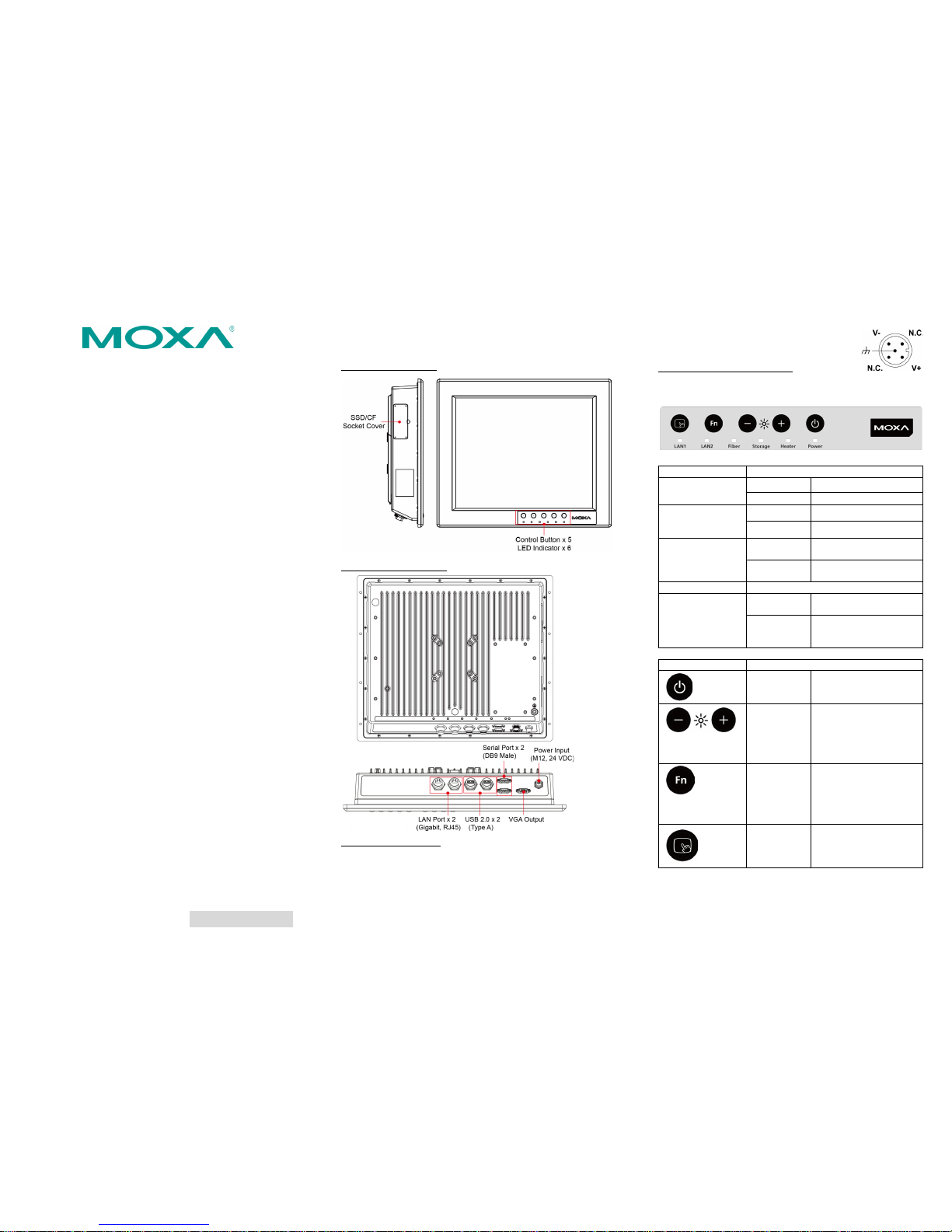
Front and Side Views
Rear and Bottom Vi ews
Connecting the Power
The power input connector is located on the left of the bottom
panel. You need to connect the power signal wires to the M12
connector. See the following figure for the pin assignment of the
M12 power connector.
When power has been connected, press Power
button on the front panel to turn on the
computer.
Front Panel LEDs and Buttons
There are six LED indicators and five control buttons on the front
panel.
LED Indicators
Function
Power
On
Power is on.
Off
Power is off.
Heater
(will be enabled
when below -20℃)
On Heater is working.
Off
Heater is not working.
Storage
Blinking Storage (CF or SSD) is
accessing.
Off
Storage (CF and SSD) is
not accessing.
Fiber
Mfr. reserved
LAN1 & LAN 2
On Network is transmitting
or receiving dat a.
Off
Network is not
transmitting or receiving
data.
Control Buttons
Function
Power
Press to turn on the
computer. Press again to
turn off the computer.
Brightness
Press + button to
increase the brightness
of the panel. Press –
button to decrease the
brightness of the panel.
Function
Customizable function
key, can be configured
by an included utility.
Default value enables a
virtual keyboard.
Touch-
screen
Touch to enable the
touchscreen function
(default). Touch again to
disable.
Page 2
– 4 – – 5 – – 6 –
www.moxa.com/support
The Americas:
+1-714-528-6777 (toll-free: 1-888-669-2872)
Europe:
+49-89-3 70 03 99-0
Asia-Pacific:
+886-2-8919-1230
China:
+86-21-5258-9955 (toll-free: 800-820-5036)
2013 Moxa Inc. All r ights reserved.
4. Connecti ng the Interfaces
EXPC-1319 perip heral interfaces are located on the bottom pane l.
All hardware interfaces ship with protective caps and tethers. To
connect the interfaces, remove the protective caps an d tethers.
The screws on the end of the tails also need to be removed. To
protect against water damage, when the connectors are not in use,
please make sure the protective caps have been securely fastened.
Connecting to a Display
Your EXPC-1319 embedded computer comes with a 15 pin fem ale
D-Sub hardware interface for VGA output. Be sure to cut the
system power before you connect or disconnect the monitor cable.
Pin
No.
Signal
Definition
Pin
No.
Signal
Definition
1
Red 9 VCC
2
Green
10
GND
3
Blue
11
NC
4 NC 12 DDC2B
Data
5
GND
13
HSYNC
6
GND
14
VSYNC
7
GND
15
DDC2B
Clock
8
GND
USB Ports
The EXPC-1319 has two USB 2.0 ports on the bottom panel. Follow
these steps to install the USB de vices.
Step 1:
Disassemble the
waterproof USB connector
into four parts.
Step 2: Connect the USB signal wires with the correct pin
definition. See the figure and t able below.
Step 3: When finished, assemble the USB parts, and connect to
the USB connector on the bottom panel of the EXPC-1319. Make
sure the connector has been securely fastened to ensure the
waterproof function.
Pin No. Definition
1
VCC 2 DATA- 3 DATA+
4
Ground
Serial Ports
The EXPC-1319 comes with two RS-232/422/485 seria l ports with
male DB9 connectors.
Step 1: Dis assemble
the waterproo f DB9
connector into four
parts.
Step 2: Connect the serial signal wires with the correct pin
definition. See the following figure and table .
Step 3: When finished, assemble the DB connector parts, and
connect to the DB9 connector on the bottom panel of the
EXPC-1319. Make sure the connector has been securely fastened
to ensure the waterproof function.
Refer to the follo wing figure an d table for ser ial port definit ions.
Pin
RS-232
RS-422
RS-485
(4-wire)
RS-485
(2-wire)
1
DCD
TxDA(-)
TxDA(-)
– 2 RxD
TxDB(+)
TxDB(+)
–
3
TxD
RxDB(+)
RxDB(+)
DataB(+)
4
DTR
RxDA(-)
RxDA(-)
DataA(-)
5
GND
GND
GND
GND
6
DSR – –
–
7
RTS – – – 8
CTS – –
–
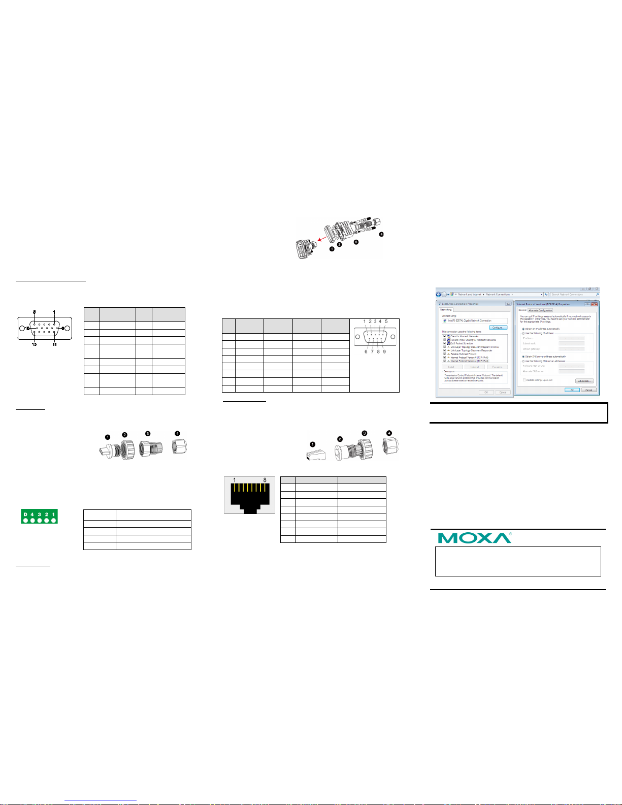
Ethernet Ports
The EXPC-1319 has two 10/100/1000 Mbps Ethernet LAN
interfaces with waterproof RJ45 connectors. Follow the steps
below to connect the LAN ports.
Step 1: Disassemble the
hardware into four parts.
Step 2: Take care to match
the correct wires and pins.
See the figure and table
below.
Pin
100 Mbps
1000 Mbps
1
ETx+
TRD(0)+
2
ETx-
TRD(0)-
3
ERx+
TRD(1)+
4 – TRD(2)+
5 – TRD(2)-
6
ERx-
TRD(1)-
7 – TRD(3)+
8 – TRD(3)-
Step 3: Pass the signal wires thr ough Part 2, 3 and 4, and connect
the wires to the RJ45 head. Next, securely refasten the assembly;
you may now connect to the LAN interface on the bottom panel.
Make sure the connector is securely fastened to ensure the
assembly rem ains waterproof. Please n ote that by default the
EXPC-1319 uses DHC P for network IP addressing.
5. Configuring the Ethernet Interface
Follow these steps to configure the Ethernet interface
Step 1: Go to Start=>Control Panel=>Network and
Internet=> Network Connections.
Step 2: In the Local Area Connection Properties screen, click
Internet Protocol (TCP/IP) and then select
Properties.
Step 3: En ter the proper IP address and netmask, and click OK.
NOTE
Refer to the User’s Man ual for addit ional configurat ion
information.
 Loading...