

Page 1

2013 Moxa Inc. All rights reserved.
P/N: 1802005100020
Moxa EtherDeviceTM Switch
EDS-P510A-8PoE Series
Hardware Installation Guide
First Edition, January 2013
Page 2

- 2 -
Overview
The Moxa EDS-P510A-8PoE series switches are Gigabit managed PoE+
Ethernet switches that come standard with eight 10/100BaseT(X),
802.3af (PoE) and 802.3at (PoE+) compliant Ethernet ports and two
combo Gigabit Ethernet ports. The EDS-P510A-8PoE Ethernet switches
provide up to 30 watts of power per PoE+ port in standard mode, and
allow high power output of up to 36 watts for industrial heavy-duty PoE
devices, such as weather-proof IP surveillance cameras with
wipers/heaters, high-performance wireless access points, and rugged IP
phones. The EDS-P510A-8PoE Ethernet switches are highly versatile, and
the SFP fiber ports can transmit data up to 120 km from the device to the
control center with high EMI immunity. The Ethernet switches support a
variety of management functions, including STP/RSTP, TurboRing, Turbo
Chain, PoE power management, PoE device auto-checking, PoE power
scheduling, IGMP, VLAN, QoS, RMON, bandwidth management, and port
mirroring. The EDS-P510A-8PoE series is designed especially for outdoor
harsh environment applications with 3KV surge resistance to keep
continuous reliability of the PoE systems.
Package Checklist
The EDS-P510A-PoE is shipped with the following items. If any of these
items are missing or damaged, please contact your customer service
representative for assistance.
• 1 EDS-P510A-8PoE EtherDevice Switch
• Hardware Installation Guide
• CD-ROM with user’s manual and Windows utility
• Moxa product warranty statement
• RJ45 to DB9 console port cable
• Protective caps for unused SFP ports
• DIN-Rail mounting kit (attached to the EDS-P510A-8PoE’s rear panel
by default)
Page 3
- 3 -
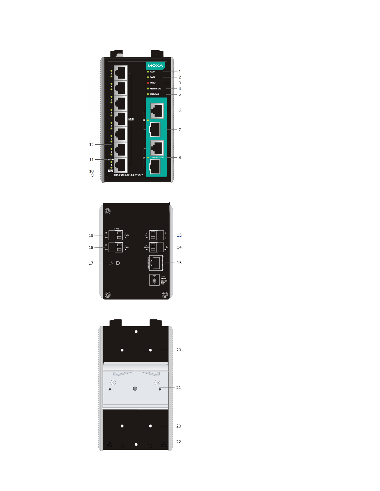
Panel Views of EDS-P510A-8PoE
Front Panel View
Top Panel View
Rear Panel View
1. Power input PWR1 LED
2. Power input PWR2 LED
3. Fault LED
4. MSTR/HEAD LED
5. CPLR/TAIL LED
6. 1000Mbps copper port of the
combo port
7. 100/1000Mbps SFP port of the
combo port
8. Gigabit port speed LED
9. Model name
10. SmartPoE LED indicator of PoE+
ports
11.
Fast Ethernet port speed LED
12.
10/100Mbps IEEE 802.3af/at
port
13.
Terminal block for digital input
14.
Terminal block for relay output
15.
RS-232 serial console port
16.
DIP switches
17.
Grounding screw
18. Terminal block for power input 1
19. Terminal block for power input 2
20.
Screw holes f
or wall mounting kit
21.
DIN rail mounting kit
22.
Heat dissipation vents
Page 4
- 4 -
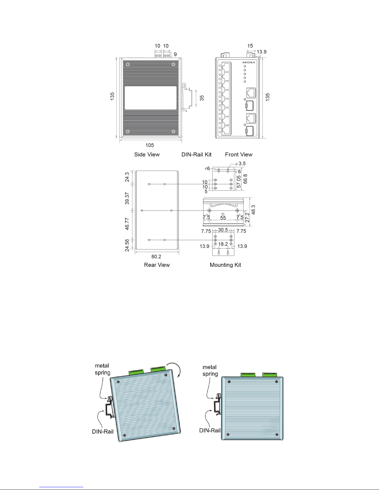
Mounting Dimensions (unit = mm)
DIN-Rail Mounting
The aluminum DIN-Rail attachment plate should already be fixed to the
back panel of the EDS-P510A-8PoE when you take it out of the box. If you
need to reattach the DIN-Rail attachment plate to the EDS-P510A-8PoE,
make sure the stiff metal spring is situated towards the top, as shown by
the following figures.
STEP 1
—Insert the top of the
DIN
-Rail into the slot just below
the
stiff metal spring.
STEP 2
—The DIN-Rail attachment
unit will snap into place as shown in
the following illustration.
To remove the EDS-P510A-8PoE from the DIN-Rail, simply reverse Steps
1 and 2 above.
Page 5

- 5 -
Wall Mounting (Optional)
For some applications, you will find it convenient to mount Moxa
EDS-P510A-8PoE on the wall, as shown in the following illustrations:
STEP 1—Remove the
aluminum DIN
-Rail
attachment plate from the
rear panel
of the
EDS
-P510A -8PoE, and
then attach the wall
mount plates
with M3
screws
, as shown in the
figure
at the right.
STEP 2—Mounting the EDS-P510A-8PoE on the wall
requires 4 screws. Use the EDS
-P510A-8PoE, with wall
mount plates attached, as a guide to mark the correct
locations of the 4 screws. The
heads of the screws
should be less than 6.0 mm in diameter, and the shafts
should be less than 3.5 mm in diameter, as shown in the
figure on at right.
NOTE
Before tightening the screws into the wall, make sure the screw
head and shank size are suitable by inserting the screw through
one of the keyhole-shaped apertures of the Wall Mounting Plates.
Do not screw the screws in all the way—leave about 2 mm to allow room
for sliding the wall mount panel between the wall and the screws.
STEP 3—Once the screws are
fixed
to the wall, insert the four
screw heads through the wide
parts of the keyhole
-shaped
apertures, and then slide
the
EDS
-P510A-8PoE downwards, as
indicated
in the figure at
the right.
Tighten the four screws for
more
stability.
Page 6

- 6 -
Wiring Requirements
WARNING
Do not disconnect modules or wires unless power has been
switched off or the area is known to be non
-hazardous. The
devices may only be connected to the supply voltage shown on
the type plate. The
devices are designed for operation with a
Safety Extra-Low Voltage. Thus, they may only be connected to
the supply voltage connections and to the signal contact with the
Safety Extra
-Low Voltages (SELV) in compliance with
IEC60950-1/EN60950-1.
ATTENTION
This unit is a built
-in type. When the unit is installed in another
piece of equipment, the equipment enclosing the unit must
comply with fire enclosure regulation IEC60950
-1/EN60950-
1 (or
similar regulation).
ATTENTION
Safety First!
Be sure to disconnect the power cord before installing and/or
wiring your Moxa EtherDevice Switch.
Calculate the maximum possible current in each power wire and
common wire. Observe all electrical code
s dictating the
maximum current allowable for each wire size.
If the current goes above the maximum ratings, the wiring could
overheat, causing serious damage to your equipment.
Please read and follow these guidelines:
• Use separate paths to route wiring for power and devices. If power
wiring and device wiring paths must cross, make sure the wires are
perpendicular at the intersection point.
NOTE
Do not run signal or communications wiring and power wiring
through the same wire conduit. To avoid interference, wires with
different signal characteristics should be routed separately.
• You can use the type of signal transmitted through a wire to
determine which wires should be kept separate. The rule of thumb is
that wiring that shares similar electrical characteristics can be
bundled together.
• You should separate input wiring from output wiring.
• We advise that you label the wiring to all devices in the system.
Page 7

- 7 -
Grounding the Moxa EDS-P510A-8PoE
Grounding and wire routing help limit the effects of noise due to
electromagnetic interference (EMI). Run the ground connection from the
ground screw to the grounding surface prior to connecting devices.
ATTENTION
This product is intended to be mounted to a well
-grounded
mounting surface such as a metal panel.
Wiring the Relay Contact
The EDS-P510A-8PoE has one relay output. The relay contact uses two
contacts of the terminal block on the EDS-P510A-8PoE’s top panel. Refer
to the next section for detailed instructions on how to connect the wires to
the terminal block connector, and how to attach the terminal block
connector to the terminal block receptor.
In this section, we illustrate the meaning of the two contacts used to
connect the relay contact.
FAULT:
The relay contacts
of the 2-pin terminal block
connector are used to detect user
-configured events.
The two wires attached to the
fault contacts form an
open circuit when a user-configured event is triggered.
If a user
-configured event does not occur, the fault
circuit remai
ns closed.
Wiring the Redundant Power Inputs
The EDS-P510A-8PoE has two sets of power inputs—power input 1 and
power input 2. The two terminal block connectors on the top-left of the
EDS-P510A-8PoE's top panel are used for the two power inputs. The top
and front views of one of the terminal block connectors are shown here.
STEP 1: Insert the negative/positive DC wires into the
V
-/V+ terminals, respectively.
STEP 2: To keep the DC wires from pulling loose, use a
small flat
-blade screwdriver to tighten the wire-
clamp
screws on the front of the terminal block connector.
STEP 3:
Insert the plastic terminal block connector
prongs into the terminal block receptor, which is
located on
the EDS-P510A-8PoE’s top panel.
Page 8

- 8 -
Wiring the Digital Inputs
The EDS-P510A-8PoE has one digital input. The DI consists of two
contacts on the terminal block connector on the EDS-P510A-8PoE’s
top-right panel. The top and front views of one of the terminal block
connectors are shown here.
STEP 1: Insert the negative (ground)/positive DI wires
into the
┴/I terminals, respectively.
STEP 2: To keep the DI wires from pulling loose, use a
small flat
-blade screwdriver to tighten the wire-
clamp
screws on the front of the terminal block connector.
STEP 3:
Insert the plastic terminal block connector
prongs into the terminal block receptor, which is
located on
the EDS-P510A-8PoE’s top panel.
Turbo Ring DIP Switch Settings
EDS-P510A-8PoE series switches are plug-and-play managed redundant
Ethernet switches. The proprietary Turbo Ring protocol was developed by
Moxa to provide better network reliability and faster recovery time. Moxa
Turbo Ring’s recovery time is less than 300 ms (Turbo Ring) or 20 ms
(Turbo Ring V2) —compared to a 3- to 5-minute recovery time for
commercial switches—decreasing the possible loss caused by network
failures in an industrial setting.
There are 4 Hardware DIP Switches for Turbo Ring on the top panel of
EDS-P510A-8PoE that can help set up the Turbo Ring easily within
seconds. If you do not want to use a hardware DIP switch to setup the
Turbo Ring, you can use a web browser, telnet, or console to disable this
function.
NOTE
Please refer to the Turbo Ring DIP Switch section and Using
Communication Redundancy
section in User’s Manual for
more detail informat
ion about the settings and usage of Turbo
Ring and Turbo Ring V2.
EDS-P510A-8PoE Series DIP Switches
The default setting for each DIP Switch is OFF.
The
following table explains the effect of
setting the DIP Switch to the ON position
.
Page 9

- 9 -
“Turbo Ring” DIP Switch Settings
DIP 1
DIP 2
DIP 3
DIP 4
Reserved for
future use.
ON: Enables this
EDS as the Ring
Master.
ON: Enables the
default “Ring
Coupling” ports.
ON: Activates DIP
switches 1, 2, 3 to
configure “Turbo
Ring” settings.
OFF: This EDS
will not be the
Ring Master.
OFF: Do not use
this EDS as the
ring coupler.
OFF: DIP
switches 1, 2, 3
will be disabled.
“Turbo Ring V2” DIP Switch Settings
DIP 1
DIP 2
DIP 3
DIP 4
ON: Enables the
default “Ring
Coupling
(backup)” port.
ON: Enables this
EDS as the Ring
Master.
ON: Enables the
default “Ring
Coupling” port.
ON: Activates
DIP switches 1,
2, 3 to configure
“Turbo Ring V2”
settings.
OFF: Enables the
default “Ring
Coupling
(primary)” port.
OFF: This EDS
will not be the
Ring Master.
OFF: Do not use
this EDS as a ring
coupler.
OFF: DIP
switches 1, 2, 3
will be disabled.
NOTE
You must enable the Turbo Ring function first before using the
DIP switch to activate the Master and Coupler functions.
NOTE
If you do not enable any of the EDS
-P510A-8PoE
switches to be
the Ring Master, the Turbo Ring protocol will automatically
choose the EDS
-P510A-8PoE with the smallest MAC address
range to be the Ring Master. If you accidentally enable more than
one EDS
-P510A-8PoE to be the Ring Master, these
EDS
-P510A-8PoE switches will auto-negotiate to determine
which one will be the Ring Master.
LED Indicators
The front panel of the Moxa EDS-P510A-8PoE contains several LED
indicators. The function of each LED is described in the following table:
LED
Color
State
Description
PWR1 AMBER
On
Power is being supplied to power input
P1.
Off
Power is not being supplied to power
input P1.
PWR2 AMBER
On
Power is being supplied to power input
P2.
Off
Power is not being supplied to power
input P2.
FAULT RED
On
When a user-configured event is
triggered.
Off
When a user-configured event is not
triggered.
Page 10

- 10 -
LED
Color
State
Description
MSTR/HEAD
GREEN
On
When the switch is set as the Master of
the Turbo Ring, or as the Head of the
Turbo Chain.
Blinking
The switch has become the Ring
Master of the Turbo Ring, or the Head
of the Turbo Chain, after the Turbo
Ring or the Turbo Chain is down.
Off
When the switch is not the Master of
this Turbo Ring or is set as the Member
of the Turbo Chain.
CPLR/TAIL GREEN
On
When the EDS
-P510A-8PoE coupling
function is enabled to form a back
-up
path, or when it's set as the Tail of the
Turbo Chain.
Blinking
When the Turbo Chain is down.
Off
When the switch disables the coupling
function.
Port 1 to
Port
8
(10M)
AMBER
On
TP port’s 10 Mbps link is active.
Blinking
Data is being transmitted at 10 Mbps.
Off
TP port’s 10 Mbps link is inactive.
Port 1 to
Port 8
(100M)
GREEN
On
TP port’s 100 Mbps link is active.
Blinking
Data is being transmitted at 100 Mbps.
Off
TP port’s 100 Mbps link is inactive.
G1 to G2
(10/100/
1000M)
AMBER
On
G1 to G2 port’s 10/100Mbps link is
active.
Blinking
Data is being transmitted at
10/100Mbps.
Off
G1 to G2 port’s 10/100Mbps link is
inactive.
G1 to G2
(1000M)
GREEN
On
G1 to G
2 port’s 1000 Mbps link is
active.
Blinking
Data is being transmitted at 1000
Mbps.
Off
G1 to G2 port’s 1000 Mbps link is
inactive.
PoE+
AMBER
On
PoE port is connected to PoE device,
using the 802.3af standard
Off
No PoE power output
GREEN
On
PoE port is connected to PoE device,
using the 802.3at standard
Off
No PoE power output
RED
On
PoE power failure:
-
Once/second: PoE detection failure
-
Twice/second: short-circuit,
overloading, or over temperature
Off
-
Page 11

- 11 -
Specifications of EDS-P510A-8PoE Series
Technology
Standards IEEE 802.3af/at for Power-over-Ethernet,
IEEE 802.3 for 10BaseT,
IEEE 802.3u for 100BaseT(X) and 100Base FX,
IEEE 802.3ab for 1000BaseT(X),
IEEE 802.3z for 1000BaseSX/LX/LHX/ZX,
IEEE 802.3x for Flow Control,
IEEE 802.1D for Spanning Tree Protocol,
IEEE 802.1w for Rapid STP,
IEEE 802.1Q for VLAN Tagging,
IEEE 802.1p for Class of Service,
IEEE 802.1X for Authentication,
IEEE 802.3ad for Port Trunk with LACP
Protocols
IGMPv1/v2, GVRP, SNMPv1/v2c/v3, DHCP
Server/Client, BootP, TFTP, SNTP, SMTP, RARP,
GMRP, LACP, RMON, HTTP, HTTPS, Telnet, Syslog,
DHCP Option 66/67/82, SSH, SNMP Inform,
Modbus/TCP, EtherNet/IP, LLDP, IEEE 1588 PTP,
IPv6
MIB
MIB-II, Ethernet-Like MIB, P-BRIDGE MIB,
Q-BRIDGE MIB, Bridge MIB, RSTP MIB, RMON MIB
Group 1, 2, 3, 9
Flow Control
IEEE 802.3x flow control, back pressure flow control
Switch Properties
Priority Queues
4
Max. Number of
Available VLANs
64
VLAN ID Range
VID 1 to 4094
IGMP Groups
256
Interface
RJ45 Ports
10/100BaseT(X) or 10/100/1000BaseT(X) auto
negotiation speed
Fiber Ports
100/1000BaseSFP slot
Console Port
RS-232 (RJ45)
LED Indicators
PWR1, PWR2, FAULT, 10/100M (TP port), G1/G2
(Gigabit port), MSTR/HEAD, CPLR/TAIL, PoE+
DIP Switch
Turbo Ring, Master, Coupler, Reserve
Alarm Contact Two relay
outputs with current carrying capacity of
0.5A @ 48 VDC
Digital Input
Two inputs with the same ground, but electrically
isolated from the electronics
• For state “1”: +13 to +30V
• For state “0”: -30 to +3V
• Max. input current: 8 mA
PoE (per port)
Max. Output Power
15.4W in 802.3af, 30W in 802.3at, 36W in high
power mode
Output Voltage
46 to 57 VDC (depends on external power supply)
Max. Output Current
350 mA in 802.3af, 600 mA in 802.3at, 720 mA in
high power mode
Max. Overload
Protection
850 mA
Page 12

- 12 -
Power
Input Voltage
48 VDC (46 to 50 VDC), redundant dual inputs
Connection
Two removable 6-pin terminal blocks
Overload Current
Protection
Present
Reverse Polarity
Protection
Present
Physical Characteristics
Casing
IP30 protection, metal case
Dimensions
80.2 × 135 × 105 mm (3.16 × 5.31 × 4.13 in)
Weight
1030 g
Installation
DIN-Rail, Wall Mounting Kit (optional kit)
Environment
Operating
Temperature
-10 to 60°C (14 to 140°F), standard models
-40 to 75°C (-40 to 167°F) for T. models
Storage
Temperature
-40 to 85°C (-40 to 185°F)
Ambient Relative
Humidity
5 to 95% (non-condensing)
Altitude
Up to 2000 M (higher altitude available on demand)
Regulatory Approvals
Safety
UL508
Traffic Control
NEMA TS2
Railway
EN 50121-4
EMI
FCC Part 15, CISPR (EN55022) class A
EMS
EN61000-4-2 (ESD), Level 3
EN61000-4-3 (RS), Level 3
EN61000-4-4 (EFT), Level 3
EN61000-4-5 (Surge), Level 3
EN61000-4-6 (CS), Level 3
EN61000-4-8
EN61000-4-11
Shock
IEC60068-2-27
Freefall
IEC60068-2-32
Vibration
IEC60068-2-6
Warranty
Time Period
5 years
Details
www.moxa.com/warranty
Technical Support Contact Information
www.moxa.com/support
Moxa Americas:
Toll
-free: 1-888-669-2872
Tel:
1-714-528-6777
Fax:
1-714-528-6778
Moxa China (Shanghai office):
Toll
-free: 800-820-5036
Tel:
+86-21-5258-9955
Fax:
+86-21-5258-5505
Moxa Europe
:
Tel:
+49-89-3 70 03 99-0
Fax:
+49-89-3 70 03 99-99
Moxa Asia
-Pacific:
Tel:
+886-2-8919-1230
Fax:
+886-2-8919-1231
 Loading...