

Moxa Technologies EDS-405A, EDS-405A-MM-SC, EDS-408A-SS-SC, EDS-408A-MM-SC, EDS-405A-SS-SC Hardware Installation Manual
...Page 1

2010 Moxa Inc. All rights reserved.
Reproduction without permission is prohibited.
P/N: 1802004000017
EDS-405A/ 408A Series
Hardware Installa tion Guide
Moxa EtherDevice™ Switch
Eighth E diti on, No vembe r 2 010
Page 2

- 2 -
Overview
The M ox a EtherDevice™ EDS-405A/408A se ri es, which i ncludes both 5
and 8-port smart Ethernet switches, is a cost-effective solution for your
Ethernet connections. In addition, the built-in smart alarm function helps
sys tem maintainers monito r th e health of your Ether net network.
Package Checklist
The Moxa EDS-405A/408A switches are sh ip p e d w ith t he f ollowin g ite ms.
If any of these items is missi ng o r da maged, please contact your
customer service representative for as s istance.
• EDS-405A or EDS-408A E thern et switch
• RJ45-to-DB9 console port cable
• Prot ective caps for u nus ed ports
• Panel mounting kit ( optional—must o rder s epa rately)
• Hardware installation guide
• CD-ROM wi th user’s manual and Wi nd o ws utility
• Warranty card
Page 3
- 3 -
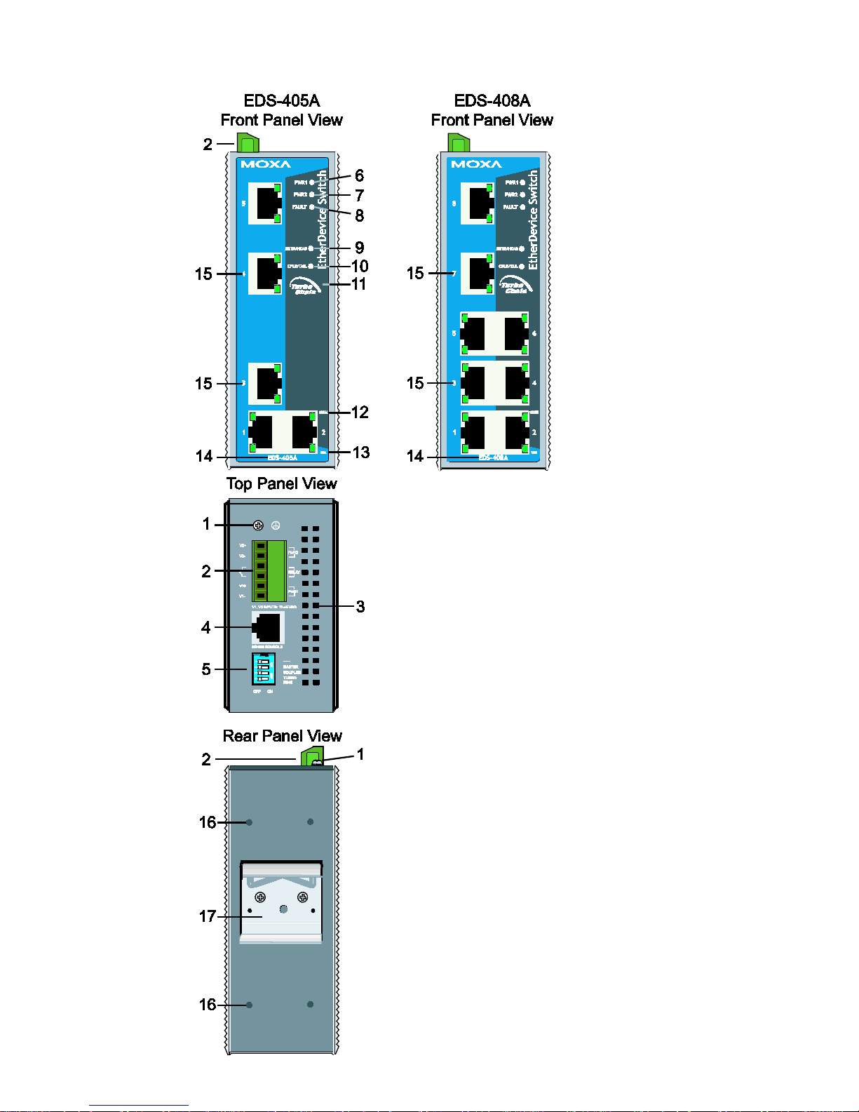
EDS-405A/408A Panel Layout (standard)
1. Groundi ng sc rew
2. Terminal block for power input
PWR1/PWR2 and rela y output
3. Heat dissipation vents
4. Console port
5. DIP switches
6. Power inpu t PWR1 LED
7. Power inpu t PWR2 LED
8. Fault LED
9. MSTR/ HEAD: LED indicator
10. CPLR/TAIL: LED indi c ator
11. Turbo Ch ai n logo
12. TP port’s 100 Mbps LED
13. TP port’s 10 Mbps LED
14. Mod el Name
15. 10/10 0BaseT(X) p o rts
16. Screw hole for wall mounting kit
17. DIN-Rail kit
Page 4
- 4 -
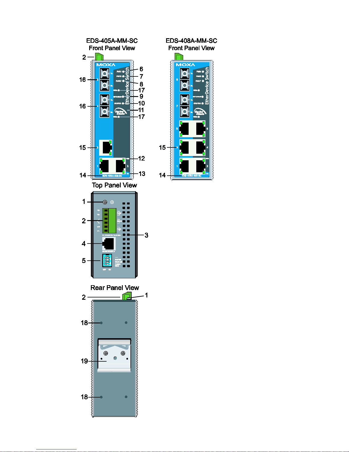
EDS-405A/408A-MM (SC-ty pe) Panel Layout
NOTE:
The appearance of the EDS-405A-SS-SC i s
identical to that of the EDS-405A-MM-SC.
The appearance of the EDS-408A-SS-SC is
identical to that of the EDS-408A-MM-SC.
1. Groundi ng sc rew
2. Terminal block for power input
PWR1/PWR2 an d rel a y output
3. Heat dissipation vents
4. Console port
5. DIP switches
6. Power inpu t PWR1 LED
7. Power inpu t PWR2 LED
8. Fault LED
9. MSTR/ HEAD: LED indicator
10. CPLR/TAIL: LED indi c ator
11. Turbo Ch ai n logo
12. TP port’s 100 Mbps LED
13. TP port’s 10 Mbps LED
14. Mod el Name
15. 10/10 0BaseT(X) p o rts
16. 100BaseF X ports
17. FX port’ s 100 Mbps L EDs
18. Screw hole for wall mounting kit
19. DIN-Rail kit
Page 5
- 5 -
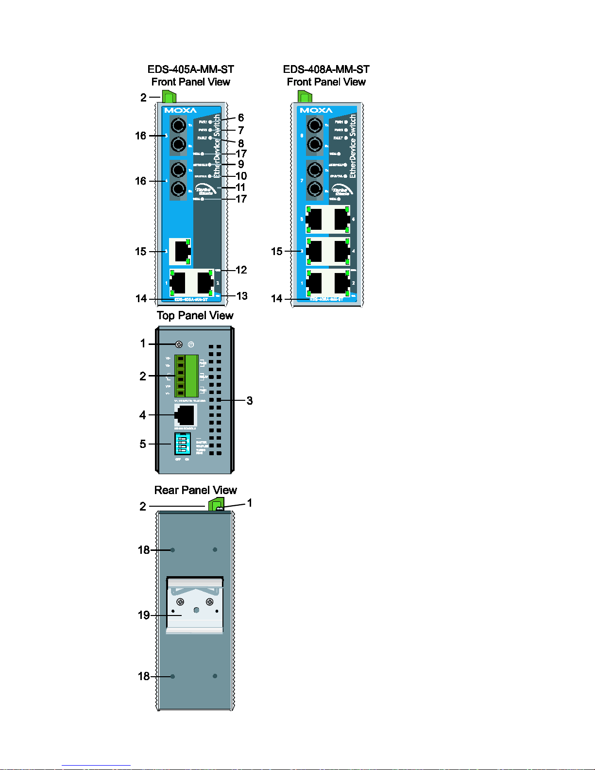
EDS-405A/408A-MM (ST-type ) Pan el L a you t
1. Groundi ng sc rew
2. Terminal block for power input
PWR1/PWR2 and rela y output
3. Heat dissipation vents
4. Console port
5. DIP switches
6. Power inp ut PWR1 LED
7. Power inpu t PWR2 LED
8. Fault LED
9. MSTR/ HEAD: LED indicator
10. CPLR/TAIL: LED indi c ator
11. Turbo Ch ai n logo
12. TP port’s 100 Mbps LED
13. TP port’s 10 Mbps LED
14. Mod el Name
15. 10/10 0BaseT(X) p o rts
16. 100BaseFX ports
17. FX port’ s 100 Mbps L EDs
18. Screw hole for wall mounting kit
19. DIN-Rail kit
Page 6

- 6 -
EDS-408A-3M Panel Layout (SC/ST-type)
NOTE:
The appearan ce of the
EDS-408A-3S-SC,
EDS-408A-1M2S-SC, and
EDS-408A-2M1S-SC are identical to
th at of the EDS-408A-3M-SC.
1. Groundi ng sc rew
2. Terminal block for power input
PWR1/PWR2 and rel ay output
3. Console port
4. DIP switches
5. Heat dissipation vents
6. Power inpu t PWR1 LED
7. Power inpu t PWR2 LED
8. Fault LED
9. MSTR/ HEAD: LED indicator
10. CPLR/TAIL: LED indi c ator
11. 10/10 0BaseT(X) p o rts
12. TP port’s 100 Mbps LED
13. TP port’s 10 Mbps LED
14. 100BaseFX ports
15. 1 FX port’s 10 0Mb ps L E D s
100M-M: mul ti mod e FX po rt
100M-S: single mode FX port
16. Mod el Name
17. Screw hole for wall mounting kit
18. DIN-Rail kit
Page 7

- 7 -
Mounting Dimensions (unit = mm)
DIN-Rail Mounting
The a luminum D I N -Rail attachment plate should already be fixed to the
back panel of the EDS-405A/408A when you ta ke it out of t he box . If y ou
need to reattach the DIN-Rail attachment plate, make sure the stiff metal
spring is situated towards the top, as shown in the following figures.
STEP 1:
Ins e rt the top o f the DI N-Rail into
th e sl ot j ust b elo w th e stiff metal
spring.
STEP 2:
The D I N-
Rail attachment unit will
snap into pl ace as sho w n.
To remov e the Mox a EtherDevice swi tc h from th e DI N -Rail, simply
rever se Steps 1 and 2 .
Page 8

- 8 -
Wall Mo un t in g (optional)
For some applications, you will find it convenient to mount the
EDS-405A/408A on the wall, as shown in the following figures.
STEP 1:
Re mov e the aluminum
DIN-Rail attachm ent p late
from the EDS-405A/408A’s
re ar panel , and t hen att ach
the wall mount plates with
M3 screws, as shown in the
diagram at the right.
⇒
STEP 2:
Mounting the EDS-405A/408A on the wall
requires 4 screws. Use the switch, with wall
mount p lates attached , as a guide to mark t h e
correct locations of th e 4 screws. The heads of
the screws shoul d be l ess than 6.0 mm in
diameter, and the shafts should be less than 3.5
mm in diameter, as sho wn in the figure at the
right.
NOTE Befo r e ti ghten ing the scr ews into the wall , make sure th e s c rew
head and shank size are suitabl e by inserting the screw i nto o ne
of the k eyhol e-shaped apertures of th e w al l mounting plates.
Do not screw the screws in completely—leave about 2 mm to allow room
for sliding the wall mount panel between the wall and the screws.
STEP 3: Once the screws are fixed in the wall, insert the four screw heads
through t he large parts of th e ke yho le-shaped apertu r es , and then slide
the EDS-405A/408A downwards, as indicated. Tighten the four screws for
added stability.
ATEX I nformatio n
1. Certificat e n umber: DEMKO 08 ATEX 0712961X
2. Ambient r ange (-40°C ≤ Tamb ≤ 75°C)
3. Certification string (Ex nC nL IIC T4)
4. Standards covered ( EN60079-0:2006, EN 60079-15:2005)
5. The condi ti ons of safe usage:
• These prod ucts must be moun ted in an I P5 4 enclosure.
• Install in an area of pollution degree 2 or less.
• Use a conductor wi re of s ize 0 . 2 mm² or gr eat e r .
• PROVISIONS SHOUL D BE MAD E, EXTERNAL TO THE APPARATUS,
TO PREVENT THE RATED VOLT AG E FROM BEING EXCEED ED BY
TRAN S I ENT DISTURBANC E S OF MORE THAN 40%.
Page 9

- 9 -
Wiring Requirements
WARNING
Sa fety Fir st!
Be sure to d isconnect the power cord befo re install ing and/or
wi ring you r Moxa Eth erDevic e S wi tch.
Calc u la te th e ma ximum po s s ib le cur rent i n each power wire and
common wire. Observe all electrical codes dictating the
maximum current allowable for each wire size.
If the current goes above the maximum ratings, the wiring could
overheat, cau s ing s er io u s damage to yo ur equi pment.
Be sure to read and follow thes e important guidelines:
• Use separate pa ths to route wiring fo r pow er and devices. If power
wiring and device wiring paths must cross, make sure the wires ar e
perpe n di cular at the in tersecti on poin t.
• NOTE: Do no t run si g nal o r communications wi ring and pow er wiring
through t he same wi re co ndui t. To avoid i nterf erence, wires wi th
different signal charact eri stics sho uld be routed sep ar atel y.
• Use the type of signal transmitted through a wire to determine which
wires sh ould be kept separate. Th e r u le o f th umb is that wiring that
shares similar electrical characteristics can be bundled together.
• Keep input w iring and output wiri ng separate.
• When nec es s ar y, you should label the wiring to all devices in the
system.
Grounding the EtherDevice Switch
Groundi ng and wi re routi ng help limi t the eff ects of noise due to
elec tro magne tic interf erence (EMI). Run the ground connecti on from the
ground screw to the g ro und ing su rf ace prio r to co nnecting devices.
ATTENTION
This pro duc t is inte n ded to be mounted to a well-grounded
mounting surface, such as a m etal panel.
Wiring the Relay Contact
The Relay Contact consi sts of t he two middle co ntacts of the terminal
block on the EDS-405A/408A’s top panel. Refer to the next s ection for
detailed instructions on how to connect the wires to the terminal block
connector, and how to attach the terminal block con nector to th e termina l
bl ock rec eptor.
In th is s e ction, we explain the meaning of the two contacts used to
co n nect t h e A larm Co ntact.
FAULT: The two middle contacts of the 6-contact
terminal block connector are used to detect bo th
po wer faults and port faults . The tw o w ire s
attached to the fault con t acts fo r m an open
circuit
when:
Page 10

- 10 -
A rel ay w arning event i s trigger ed .
OR
The EDS-405A/408A is the Mast er of thi s T urbo
Ring, and the Turbo Ri ng is broken.
OR
There i s a start-up fail ure.
If none of th ese thr e e conditions i s satisfi ed, the
fault circuit will remain closed.
Wiring the Redundant Power Inputs
The top tw o contacts and the bottom two conta cts of the 6 -contact
terminal block connector on the EDS-405A/408A’s top panel are used for
the EDS-405A/408A’s two DC inputs. Top and front views of one of the
terminal bloc k connec tors are shown in the following figures:
STEP 1: Insert the negative/positive DC wires into
the V-/V+ terminals, respectively.
STEP 2: To keep the DC w ires from pu lling
loose,
use a smal l f lat-b lade screwd r iver to tight en the
wire-clamp screw s on the fr ont o f the terminal
block connector.
STEP 3: Insert the plastic terminal block
connector pron gs into the te rmina l block r e ceptor ,
whic h is located on the EDS-405A/408A’s top
panel.
ATTENTION
Before con necting the EDS-405A/408A to the DC power i n puts ,
make sure t h e DC p ower s ource voltage i s stabl e.
Communication Connections
EDS-408A models have 5, 6, or 8 10/100BaseT(X) Ethernet ports, and 3,
2, or 0 (zero) 100BaseFX (SC/ST-typ e c on n ector) fiber por ts. EDS-405A
models have 3 or 5 10/100BaseT(X) Ethernet ports, and 2 or 0 (zero) 100
BaseFX (SC/ST-t ype connector) fib er por ts.
10/100 B ase T(X ) Eth e rnet Port Conn ec ti on
The 10/ 100Bas eT(X) ports located on the EDS’s fron t p anel ar e u sed to
co n nect to Ether net-enabled devices.
Next, we s h ow pinouts f o r b o th MDI (NIC-type) ports and MDI-X
(HUB/Switch-ty pe) ports , a nd also show cable wiri ng di agrams for
straight-through and cross-over E t hern et c a b l es.
Page 11

- 11 -
MDI Port Pinout s MDI-X Port Pinout s 8-pin RJ45
Pin Signal Pin Signal
1 Tx+ 1 Rx+
2 Tx- 2 Rx3 Rx+ 3 Tx+
6 Rx- 6 Tx-
RJ45 (8-pin) to RJ45 (8-pi n ) Strai ght-through Cable
Wiring
RJ45 (8-pin) to RJ45 (8-pi n ) C r o ss -over Cable Wiring
100Ba se FX Ethe r ne t Port Connecti on
The conc ept behind t he SC/ST port and cable is qui te straightforward.
Suppose you are connecting devices I and II; contrary to electrical signals,
optical signals do not require a circuit in order to transmit data.
Consequently , one of t he optic a l line s is u se d t o t ran smit dat a fr om dev ice
I t o d ev ic e I I , an d t h e ot her o p t ical l in e is u s ed t r ansmit d ata fr o m device
II to devic e I, fo r f ull-duplex transmissi on.
Remember to connect the Tx (transmit) port of device I to the Rx (receive)
port of device II, and the Rx (receive) port of device I to the Tx (transmit)
port of device II. If you make your own cable, we suggest labeling the two
sides of the same line with the same letter (A-to-A and B-to-B, as shown
below, or A1-to-A2 and B1-to-B2).
SC-Port Pinout s SC-Port to SC-P o rt Cable Wirin g
Page 12

- 12 -
ST-Port Pi nou ts ST-Port to ST-Po rt Cable Wi rin g
ATTENTION
This i s a Class 1 Laser/LED prod uct. To avoi d causi ng se rious
da mage to yo u r ey es, do no t stare di r ec tly into the laser beam.
Redundant Power Inputs
Both power inputs can be connected s im u lta n eously to li ve DC power
sources. If one power source fails, the other live source acts as a backup,
and au to m ati cal l y suppl ies the EDS-405A/408A with power.
Relay Contact
The M ox a EtherDevice swi tc h has on e relay conta c t located on the to p
panel. For detailed instructions on how to connect the relay contact power
wires to the two middle con tacts of the 6-contact terminal block
connector, see the Wiring the Relay Contact section. A typical scenario
would be to connec t the fault ci rc uit to a wa rning light lo c ated in t he
control room. The light can be set up to switch on when a fault is detected.
The relay contact has two terminals that form a fault circuit for connecting
to an alarm system. T h e two wires attached to the fault contacts form an
open circuit when (1) a relay warning event is triggered, (2) the
EDS-405A/408A is th e Master of this T urbo Ring, and th e Turbo Ring is
broken, or (3) there is a start-up failure. If none of these three conditions
occur, the fault circuit will be closed.
Turbo Ring DIP Switch Se t tings
EDS-405A/408A seri es switches are plug-and-pl ay m anag ed r e du n dant
Ethernet switches. The proprietary Turbo Ring protocol was developed by
Moxa to provide better network reliability and faster recovery time. Moxa
Turbo Ring’s recovery time is less than 300 ms (Turbo Ring) or 20 ms
(Turbo Ring V2) —compared to a 3 to 5-minute reco very time for
commercial sw itches—decreasi ng t he possible lo ss c aus ed b y networ k
failures in an industrial setting.
There are 4 Hardware DIP Switches for Turbo Ring on the top panel of the
EDS-405A/408A that can b e used to set up the Turbo Ring easil y within
seconds. If you do not want to use a hardware DIP switch to set up Turbo
Ring, you can us e a we b b ro wser, Tel net, or console to disabl e this
function.
NOTE Refer to the T urbo Ring D IP Swi tch section a nd U sing
Communicati on Redunda nc y secti on in th e user’s manu al f or
detailed information about the s et ti ng s and us age of T urbo Ring
and Turbo Ring V2.
Page 13

- 13 -
EDS-405A/408A Series DIP Switches
The defaul t setting f o r each DIP Sw itch is OFF. T he
fo llo wing tab le explains the effect of s etting the DI P
Sw itc h to t he ON position.
“Turbo Ring” DIP Switch Settings
DIP 1 DIP 2 DIP 3 DIP 4
Reserved for
future us e.
ON: Enables this
EDS as th e R in g
Master.
ON: Enables the
default “Ring
Coupling” ports.
ON: Acti v ates DIP
switches 1, 2, 3 to
configure “Turbo
Ring” set ti ngs .
OFF: This EDS
will not be the
Ring Mas ter.
OFF: Do no t use
this EDS as the ring
coupler.
OFF: DIP switches
1, 2, 3 wi ll be
disabled.
“Tur bo Ring V2” DIP Switch Settings
DIP 1 DIP 2 DIP 3 DIP 4
ON: E nab les
th e default
“Ring Coupling
(backup)”
port.
ON: Enables this
EDS as th e R in g
Master.
ON: Enables the
default “Ring
Coupling” port.
ON: Acti v ates DIP
switches 1, 2, 3 to
configure “Turbo
Ring V2” s etti ngs .
OFF: Enables
th e default
“Ring Coupling
(primary)”
port.
OFF: This EDS
will not be the
Ring Mas ter.
OFF: Do no t use
this EDS as a ri ng
coupler.
OFF: DIP sw
itches
1, 2, 3 wi ll be
disabled.
NOTE If you do no t e nable an y o f the EDS-40 5A/408A s w itch es to be
the Ring Master, the Turbo Ring protocol will automatically
choose the EDS-405A/408A with the smallest MAC address range
to be the Ri ng Master. If you accid entally enabl e more than o ne
EDS-405A/408A to be the R ing Master, these ED S -405A/408A
swit ch e s will a ut o-negotiate to determine which switch
will be t he
Ring Mas ter.
NOTE To switch on the Mas ter or Cou pler func ti ons of the DIP switch,
you need to enab le t h e Tu r b o Ring Po le f irs t.
LED Indicators
The re ar e sev era l LEDs on the EDS’s front panel. The function of each LED
is described in the following table.
LED Color State Description
PWR1 AMBER On
Power is being supplied to power input
PWR1.
Off Power is not being supplied to power
input PWR1.
Page 14

- 14 -
PWR2 AMBER On
Power is being supplied to power input
PWR2.
Off Power is not being supplied to power
input PWR2.
FAULT RED On W hen (1) a relay w arning event is
trig ger ed, (2) the ED S-405A/408A i s
the M ast er of this Turbo Ring, and the
Turbo Ring is broken, or (3) start-up
failure.
Off When a r el ay warning event is no t
triggered.
MSTR/HEAD GREEN On When the EDS-405A/408A is set as the
Master o f the Turbo Ring, or as the
Head of th e Turbo Chain.
Blinking The EDS-405A/408A h as become the
Ring Mas ter of the Turbo Ring, or the
Head of th e Turbo Chain, after the
Turbo Ring or the Turbo Chain is down.
Off When th e EDS-405A/408A is n ot the
Master of thi s T urbo Ring or is set as
the M ember of th e Tu rbo Chain.
CPLR/TAIL GREEN On W hen the EDS-405A/408A coupling
function is enable d to f o rm a back-up
path, or when it's se t as the Tail of the
Turbo Ch ain.
Blinking When th e Turbo Ch ai n is down.
Off When the EDS-405A/408A disables the
coupl ing functi o n, o r is set as the
Memb er of th e Turb o Chain.
10M
(TP)
GREEN On TP port’s 10 Mbps link is active.
Blinking Data is being transmitted at 10 Mbps.
Off TP Port’s 10 Mbps link is inactive.
100M
(TP)
GREEN On TP port’s 100 Mbps l ink is active.
Blinking Data is being transmitted at 100 Mbps.
Off TP Port’s 100 Mbps link is inactive.
100M
(FX)
GREEN On FX po rt’ s 100 Mbps is ac ti ve.
Blinking Data is being transmitted at 100 Mbps.
Off FX port’s 100 Mbps i s inactive.
Auto M D I/MDI-X Conne c tion
The Auto MDI/MDI-X function al low s users to co nnect th e
EDS-405A/408A’s 10/100B aseTX port s to any ki nd o f Ethe rnet device,
without needing to pay attention to the type of Ethernet cable being used
for the connection. This means that you can use either a straight-through
cable o r cross-over cable to con ne ct the EDS-405A/408A to Ethernet
devices.
Page 15

- 15 -
Specifications
Technology
Standards IEEE802.3, 802.3u, 802.3x, 802.1D, 802.1Q,
802.1w, 802.1p
Protocols IGMP V1/V2 device, GMRP, GVRP, SNMPv1/ v2c/v3,
DHCP S erver/Client, T F TP, SNTP, SMTP, RARP,
RMON, HTTP, Telnet, Syslog, DHC P Option
66/67/82, Boo tP, LLD P, Modb us T CP, I Pv 6
MIB MIB-II, E th ernet-L ike MI B, P-BRIDG E MIB, RMON
MIB Group 1, 2, 3, 9, Bridg e MIB, RST P MIB
Forwarding and
Filtering Rate
148810 pps
Processing Type Store an d Forwa rd
Flow Control IEEE802.3x fl ow control, back press ure flow control
Interface
RJ45 Ports 10/100BaseT(X) auto negotiation speed, F/H duplex
mode, and auto MDI/MDI-X connection
Fiber Ports 100BaseFX ports (SC/ST connector)
Console RS-232 (RJ45)
LED Indicators PWR1, P W R2, FAUL T , 10/100M ( TP port),
100M (Fi b er Port) , CPLR/TAIL and MST R/HEAD
Relay Contact One relay output with current carrying capacity of 1A
@ 24 VD C
DIP Switc hes Master, Co upler, T urbo Ring, Reserve
Optical Fiber
Multi-mode Single-mode
Wavelength
1300 nm 1310 nm
Max. Tx
-10 dB m 0 dBm
Min. Tx
-20 dB m -5 dBm
Rx Sensitivity
-32 dB m -34 dB m
Link Budget
12 dB 29 dB
Typical Distance
5 km
a
, 4 kmb 40 kmc
Saturation -6 dBm -3 dBm
a. when using [50/125 μm, 800 MHz*km] cable
b. when using [62.5/125 μm, 500 MHz*km] cable
c. when using [9/125 μm, 3.5 PS/(nm*km)] cable
Power
Inp ut V oltage EDS-405A/408A:
12 to 45 VD C, redu ndant i np uts
EDS-408A-3S-SC-48:
±24/± 48 VDC (-60 to -19 VDC or 19 to 6 0
VDC), red undant i np ut s ( T he mixing o f
power polarity system is prohibi ted.)
Inp ut C urrent (@ 24 V) EDS-405A: Max. 0.24 A
EDS-408A: Max. 0.21 A
EDS-405A-MM, EDS-405A-SS: Max. 0.32 A
EDS-408A-MM, EDS-408A-SS: Max. 0.26 A
EDS-408A-3M/3S/2M1S/1M2S: Max. 0.32 A
Connection One r emo vab le 6 -pin terminal block
Overload Current Protection Present
Re ver se Po l ar i ty Pro te c ti on Present
Page 16

- 16 -
Physical Characteristics
Housing Me ta l, IP30 pr otect ed
Dimensions 53.6 × 135 × 1 05 mm
Weight 0.65 kg (EDS-405A mod els)
0.89 kg ( EDS-40 8A model s)
Installation DIN-Rail, Wall Mounting (optional kit)
Environmental Limits
Operating Temperature 0 to 60°C (32 to 140°F) ;
-40 to 75 °C (-40 to 167°F ) for -T models
Sto rag e Temperatur e -40 to 85 °C (-40 to 185°F )
Ambient Relative Humidity 5% to 9 5% (no n-condensing)
Regu l a tor y A ppro va l s
Safety EDS-405A/40 8A : U L 60950-1, UL 508, CSA
C22.2 No. 6095 0-1, EN60950-1
EDS-408A-3S-SC-48: UL508 (Pending)
EMI FCC Part 15, CISPR (E N5502 2) c lass A
EMS EN61000-4-2 (ESD), Level 3
EN61000-4-3 (RS) , Level 3
EN61000-4-4 (EFT), Level 3
EN61000-4-5 (Surge), Level 3
EN61000-4-6 (C S ), Level 3
Shock IEC60068-2-27
Freefall IEC60068-2-32
Vibration IEC60068-2-6
WARRANTY 5 ye ar s
Technical Support Contact Information
www.moxa.com/support
Mox a Americas
:
Toll-f r ee: 1-888-669-2872
Tel: 1-714-528-6777
Fax: 1-714-528-6778
Moxa Chi na (Shanghai o f f ice)
:
Toll-f r ee: 800-820-5036
Tel: +86-21-5258-9955
Fax: +86-21-5258-5505
Moxa Europe
:
Tel: +49-89-3 70 03 99-0
Fax: +49-89-3 70 03 99-99
Mox a As ia-Pacific:
Tel: +886-2-8919-1230
Fax: +886-2-8919-1231
 Loading...