

Page 1

DR-120 Series
Quick Installation Guide
Edition 1.0, January 2017
Technical Support Contact Information
www.moxa.com/support
Moxa Americas:
Toll
-free: 1-888-669-2872
Tel:
1-714-528-6777
Fax:
1-714-528-6778
Moxa China (Shanghai office):
Toll
-free: 800-820-5036
Tel:
+86-21-5258-9955
Fax:
+86-21-5258-5505
Moxa Europe:
Tel:
+49-89-3 70 03 99-0
Fax:
+49-89-3 70 03 99-99
Moxa Asia-Pacific:
Tel:
+886-2-8919-1230
Fax:
+886-2-8919-1231
Moxa India:
Tel:
+91-80-4172-9088
Fax:
+91-80-4132-1045
2017 Moxa Inc. All rights reserved.
Page 2
- 2 -
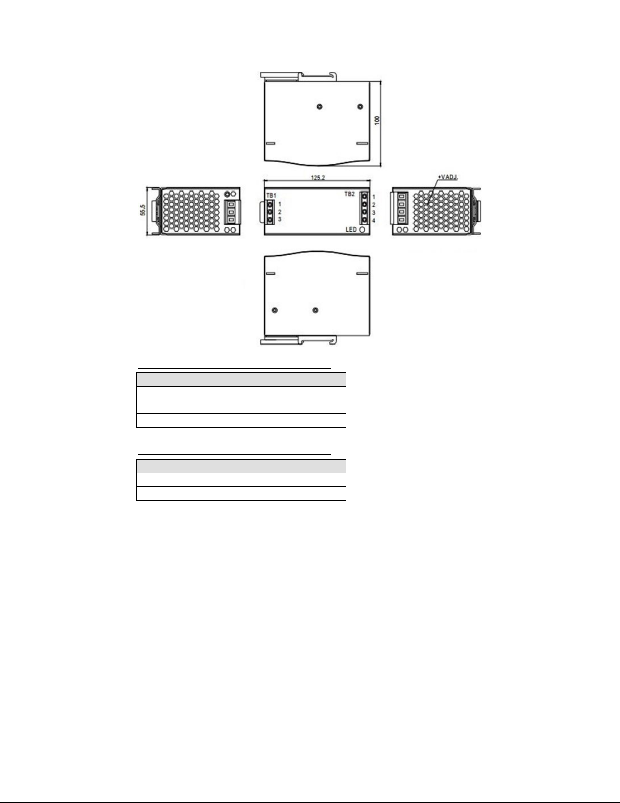
Dimensions
Terminal Pin No. Assignments (TB1)
PIN No.
Assignment
1
FG
2
AC/N (DC+)
3
AC/L (DC-)
Terminal Pin No. Assignments (TB2)
PIN No.
Assignment
1, 2
DC Output V+
3, 4
DC Output V-
Mounting Instructions
Mounting: Mount only as shown in figure, with input terminals facing
downwards to allow sufficient cooling.
Admissible DIN rails: TS35/7.5 or TS35/15.
To attach the DR-120 to the rail:
1. Rotate the DR-120 backwards, as shown in the figure.
2. Fit the top of the DR-120 over the top hat rail.
3. Slide the DR-120 downwards until it hits the stop.
4. Push the bottom of the DR-120 forward until it snaps into place.
5. Move the DR-120 back and forth to make sure it is locked in place.
Page 3

- 3 -
Installation
1. To prevent the unit from overheating, always allow sufficient
clearance around the unit for proper ventilation: 5 mm left and right,
40 mm above, and 20 mm below. You should also keep a 10 to 15 cm
clearance from adjacent devices that act as a heat source.
2. The appropriate mounting orientation is vertical, with input terminals
on the bottom and output o n the top of the DR-120. Other mounting
orientations, such as upside down, horizontal, or table-top, are not
allowed.
3. Use copper wire only; the recommended wiring is shown below.
AWG
18
16
14
12
10
Rated Current
(Amps)
6 6-10 13-16 16-25 25-32
Lead cross-section
(mm2)
0.75 1.00 1.5 2.5 4
Note:
When 5 or more wires are connected to the unit, the current
carried
by each wire could be 20% less than the current listed above.
Make sure that all strands of each wire are proper ly inserted into the
terminal connection, and that the screw terminals are securely fixed
to prevent poor contact. If the power supply has multiple output
terminals, make sure each contact is conne ct ed to wires to prevent
stress on a single contact from too much current.
4. Use wire that can withstand temperatures of at least 80°C, such as
UL1007.
5. Suggested fuses and the maximum number of the PSUs that can be
connected to a circuit breaker at 230 V a re shown as below:
Model Fuse
Circuit breakers
C16
D16
DR-120
F4A/H250W
5
7
6. The recommended wire strapping length is 5 mm (0.197 inch).
Page 4

- 4 -
7. Use a slotted type 4 mm screwdriver.
8. Use the following torque settings for terminals:
Model
I/P
O/P
DR-120
10 kgf-cm (9 in-lb)
10 kgf-cm (9 in-lb)
Important Safety Precautions
Before working with a power supply, be sure to read and understand
these instructions carefully and complete ly. You should also follow any
notes or instructions on the unit itself.
1. Risk of electrical shock and energy Hazard: If the device fails, it
must be examined by a qualified technician. Do not remove the
DIN-rail power supply casing your s elf.
2. Risk of electric arcs and electric shock (danger to life): Do not
connect the primary and secondary sides together, since doing so
could result in life threatening shocks.
3. Risk of burn hazard: Do not touch the unit while it is in op eration or
shortly after it has been disconnected.
4. Risk of fire and short circuits: Openings on the product should be
protected from foreign objects and dripping liquids.
5. Pollution level: Only install the unit in a pollution level degree 2
environment.
6. Humidity warning: Do not install the unit in locations with high
humidity, or near water.
7. The maximum operating temperature for the DR-120 is:
Model
Temperature
DR-120
60°C
8. The FG ( ) must be connected to PE (Protective Earth).
9. Output current and output wattage must not exc eed the rated values
in the product’s specifications.
10. Before doing any installation, maintenance, or modification work,
disconnect the system from the power source. Make sure that
inadvertent connection in circuit will be impossible!
11. For continued protection against risk of fire, replace only with fuses of
the same type and rating.
 Loading...