

Page 1

DA-IRIGB-4DIO-PCI104-EMC4 Module
User’s Manual
Edition 2.0, February 2017
www.moxa.com/product
© 2017 Moxa Inc. All rights reserved.
Page 2

DA-IRIGB-4DIO-PCI104-EMC4 Module
User’s Manual
The software described in this manual is furnished under a license agreement and may be used only in accordance with
the terms of that agreement.
Copyright Notice
© 2017 Moxa Inc. All rights reserved.
Trademarks
The MOXA logo is a registered trademark of Moxa Inc.
All other trademarks or registered marks in this manual belong to their respective manufacturers.
Disclaimer
Information in this document is subject to change without notice and does not represent a commitment on the part of
Moxa.
Moxa provides this document as is, without warranty of any kind, eit her expres sed or i mplied, including, but not limited
to, its particular purpose. Moxa reserves the right to make improvements and/or changes to this manual, or to the
products and/or the programs described in this manual, at any time.
Information provided in this manual is intended to be accurate and reliable. However, Moxa assumes no responsibility for
its use, or for any infringements on the rights of third parties that may result from its use.
This product might include unintentional technical or typographical errors. Changes are periodically made to the
information herein to correct such errors, and these changes are incorporated into new editions of the publication.
Technical Support Contact Information
www.moxa.com/support
Moxa Americas
Toll
-free: 1-888-669-2872
Tel:
+1-714-528-6777
Fax:
+1-714-528-6778
Moxa China (Shanghai office)
Toll
-free: 800-820-5036
Tel:
+86-21-5258-9955
Fax:
+86-21-5258-5505
Moxa Europe
Tel:
+49-89-3 70 03 99-0
Fax:
+49-89-3 70 03 99-99
Moxa Asia
-Pacific
Tel:
+886-2-8919-1230
Fax:
+886-2-8919-1231
Moxa India
Tel:
+91-80-4172-9088
Fax:
+91-80-4132-1045
Page 3

Table of Contents
1. Introduction ...................................................................................................................................... 1-1
Overview ........................................................................................................................................... 1-2
Package Checklist ............................................................................................................................... 1-2
Product Features ................................................................................................................................ 1-2
Product Specifications ......................................................................................................................... 1-2
2. Hardware Installation ....................................................................................................................... 2-1
Block Diagram .................................................................................................................................... 2-2
Pin Assignments ................................................................................................................................. 2-2
IRIB-B Signal Input ..................................................................................................................... 2-2
Digital Input and Digital Output ..................................................................................................... 2-2
Installing the DA-IRIGB-4DIO-PCI104-EMC4 .......................................................................................... 2-3
3. Software Installation and Configuration ........................................................................................... 3-1
Installing the IRIG-B Driver in Linux...................................................................................................... 3-2
Online Installation ....................................................................................................................... 3-2
Off-line Installation ...................................................................................................................... 3-3
Using the timesync Daemon in Linux ..................................................................................................... 3-4
Examples ................................................................................................................................... 3-5
Configuring the timesync Daemon ................................................................................................. 3-5
Using the IRIG-B Utility in Linux ........................................................................................................... 3-5
Examples ................................................................................................................................... 3-8
Installing the IRIG-B Driver in Windows 7 ............................................................................................ 3-10
Installing the IRIG-B Utility in W i n dows 7 ............................................................................................ 3-12
Using the IRIG-B Utility in Windows 7 ................................................................................................. 3-15
Configuring IRIG-B Paramet er s .......................................................................................................... 3-16
Input Signal Type ...................................................................................................................... 3-16
IRIG-B Parity Mode .................................................................................................................... 3-17
Configuring Time Synchronization Settings in Windows 7 ....................................................................... 3-18
Selecting a Time Input Source .................................................................................................... 3-18
Synchronizing with System Time ................................................................................................. 3-18
Configuring Digital Output and Inpu t Status ......................................................................................... 3-19
Using the mxIrigUtil Command ........................................................................................................... 3-20
4. API Reference ................................................................................................................................... 4-1
Get IRIG-B Board Hardware ID ............................................................................................................. 4-2
Open IRIG-B Device ............................................................................................................................ 4-2
Close IRIG-B Device ............................................................................................................................ 4-2
Get Digital Input Signal ....................................................................................................................... 4-2
Get Digital Output Signal ..................................................................................................................... 4-3
Get IRIG-B Parity Check Mode .............................................................................................................. 4-3
Get Input Interface ............................................................................................................................. 4-3
Get IRIG-B Output Parity Check Mode ................................................................................................... 4-4
Get Output Interface ........................................................................................................................... 4-4
Get Pule Per Second Output Width ........................................................................................................ 4-4
Get IRIG-B Signal Status ..................................................................................................................... 4-5
GET RTC Synchronization Source .......................................................................................................... 4-5
Get RTC from IRIG-B Device ................................................................................................................ 4-5
Set Digital Output Sig nal ..................................................................................................................... 4-6
Set IRIG-B Input Parity Check Mode ..................................................................................................... 4-6
Set Input Interface ............................................................................................................................. 4-6
Set IRIG-B Output Parity Check Mode ................................................................................................... 4-7
Set Output Interface ........................................................................................................................... 4-7
Set Pulse Per Second Output Width ....................................................................................................... 4-7
Set RTC Synchronization Source ........................................................................................................... 4-7
Set RTC to IRIG-B Device .................................................................................................................... 4-8
Synchronize System Local Time with IRIG RT C ....................................................................................... 4-8
IRIG-B Program Example ..................................................................................................................... 4-8
Page 4

Page 5

1
1. Introduction
Thank you for purchasing Moxa’s DA-IRIGB-4DIO-PCI104-EMC4 module for embedded computers that support
the PCI/104 interface.
The DA-IRIGB-4DIO-PCI104-EMC4 module features 3 digital inputs and 4 digital outputs and provides
precision timing information using IRIG-B input signals.
The following topics are covered in this chapter:
Overview
Package Checklist
Product Features
Product Specifications
Page 6

DA-IRIGB-4DIO-PCI104-EMC4 Module Introduction
1-2
Overview
The DA-IRIGB-4DIO-PCI104-EMC4 module features 3 digital inputs and 4 digital outputs, and provides
precision timing information using IRIG-B input signals. The module is designed for embedded computers that
support the PCI/104 interface. The DA-IRIGB-4DIO-PCI104-EMC4 module includes two DB9 connectors for
IRIG-B input signals and DIOs in embedded computers.
The DA-IRIGB-4DIO-PCI104-EMC4 module includes jumpers that enable you to configure the I/O base address
and the INT vector for each port. In addition, the built-in EMC level 4 protection safeguards the module
connected to the IRIG-B input signals and digital input and digital output devices.
Package Checklist
MOXA performs a careful mechanical and electrical inspection of each module prior to shipping. Your module
should arrive in perfect electrical order, free of any marks or scratches. Please handle the module by the edges
only, since your body’s static charge can damage the integrated circuits. When the module is not in use, keep
it in the anti-static package provided. You may also use this package to return the module if it requires repair.
The DA-IRIGB-4DIO-PCI104-EMC4 module is shipped with the following items:
• DA-IRIGB-4DIO-PCI104-EMC4 module
• 2 DB9 connectors
• 4 15 mm M/F M3x6/M3x7 spacers
• 4 4.8 mm M/F 4-40x7/4-40x4.75 spacers
• 4 screws
• Quick installation guide (printed)
• Warranty card
NOTE
Please notify your sales representative if any of the above items are
missing or damaged.
Product Features
The DA-IRIGB-4DIO-PCI104-EMC4 module features the follow ing:
• 1 IRIG-B signal input port to support S/W controlled TTL/differential signal input
• 3 digital inputs, 4 digital outputs
• Built-in EMC level 4 protection
• Configurable IRQ and I/O settings
• Onboard status LED indicators for IRIG-B signal input
Product Specifications
Hardware
Communication Controller:
FPGA Cyclone IV @ 25 MHz
Bus:
PCI/104
Connectors:
2-pin wafer, 10-pin wafer
Jumper:
PCI resource
Interface
Connector:
DB9 male
Protection
ESD Protection:
8 kV contact, 15 kV Air ESD protection
Page 7

DA-IRIGB-4DIO-PCI104-EMC4 Module Introduction
1-3
Surge Protection:
2 kV line-to-line and 4 kV line-to-ground surge protection, 8/20 µs waveform
Input Signals
IRIG
-B: TTL or differential
Time Code Input
IRIG
-B: Based on the IRIG STANDARD 200-04 and IEEE 1344
Precision and Accuracy
Accuracy (
Time Synchronization): ±1 µs
Accuracy (Free Running):
±500 ms @ 24 hr
Timebase Precision:
±40 ns
Digital Input
Input Channels:
3, source type
Input Voltage:
0 to 30 VDC
Digital Input Levels for Dry Contacts:
• Logic level 0: Close to GND
• Logic lev
el 1: Open
Digital Input Levels for Wet Contacts:
• Logic level 0: +3 V max .
• Logic level 1: +10 V to +30 V (source to D I )
Isolation:
3 kV optical isolation
Connector Type:
DB9 male
Digital Output
Output Channels:
4, sink type
Output Current:
Max. 200 mA per channel
On
-state Voltage: 24 VDC nominal, open collector to 30 V
Isolation:
3 kV optical isolation
Connector Type:
DB9
Operating Systems
Windows:
Windows 7E
Linux:
Debian 7
Physical Characteristics
Dimensions:
90 x 96 mm (3.54 x 3.78 in)
Environmental Limits
Operating Temperature:
-10 to 60°C (14 to 140°F)
Storage Temperature:
-40 to 85°C (-40 to 185°F)
Ambient Relative Humidit y:
5 to 95% (non-condensing)
Altitude:
Up to 2000 m
Standards and Certifications
EMC:
CE, FCC
EMI
: EN 55032, EN 61000-3-2, EN 61000-3-3, FCC Part 15 Subpart B Class A
EMS:
EN 55024, IEC 61000-4-2, IEC 61000-4-3, IEC 61000-4-4, IEC 61000-4-5, IEC 61000-4-6, IEC
61000
-4-8, IEC 61000-4-11
Green Product:
RoHS, CRoHS, WEEE
MTBF (mean time between failures)
Time:
1,145,189 hrs
Database:
Telcordia (Bellcore), GB
Power Requirements
Power Consumption:
2 W
Warranty
Warranty Period:
5 years
Page 8

2
2. Hardware Installation
This chapter explains how to install the DA-IRIGB-4DIO-PCI104-EMC4 module.
The following topics are covered in this chapter:
Block Diagram
Pin Assignments
IRIB-B Signal Input
Digital Input and Digital Output
Installing the DA-IRIGB-4DIO-PCI104-EMC4
Page 9
DA-IRIGB-4DIO-PCI104-EMC4 Module Hardware Installation
4-2
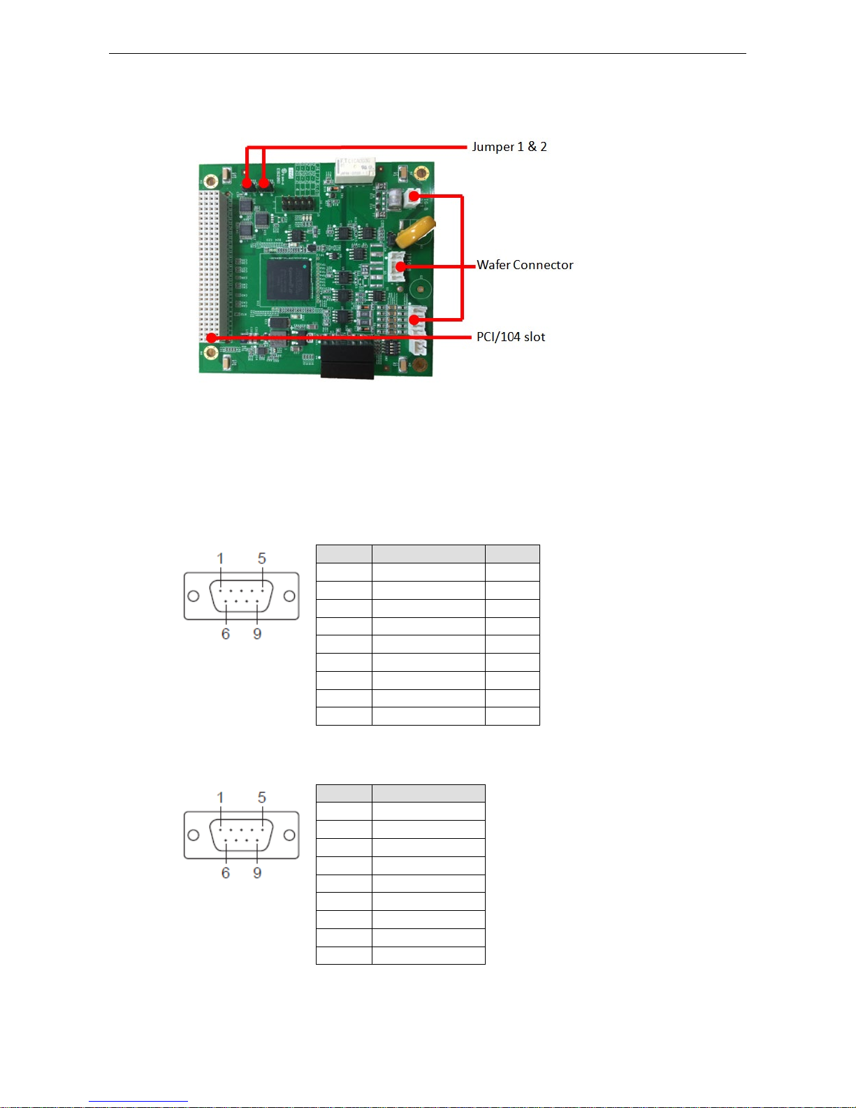
Block Diagram
Pin Assignments
This section includes the pin assignment for the male DB9 connectors to connect to an IRIG-B signal source or
a digital input (DI) or d i gital output (DO) device.
IRIB-B Signal Input
Pin Differential TTL
1 – –
2 – –
3 Data + TTL
4 Data - GND
5 – –
6 – –
7 – –
8 – –
9 – –
Digital Input and Digital Output
Pin 3DIs, 4DOs
1 DO 0
2 DO 1
3 DO 2
4 DO 3
5 DO COM
6 DI 0
7 DI 1
8 DI 2
9 DI Source
Page 10
DA-IRIGB-4DIO-PCI104-EMC4 Module Hardware Installation
4-3
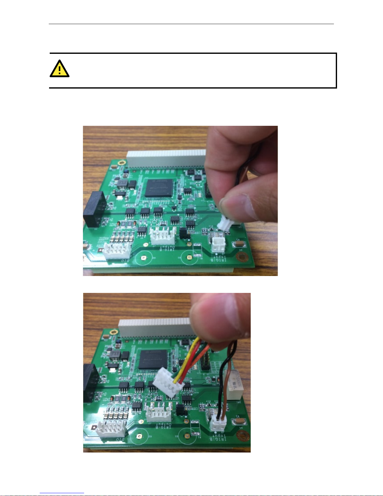
Installing the DA-IRIGB-4DIO-PCI104-EMC4
ATTENTION
To prevent damage to your system or the main board, make sure that you turn off the embedded computer
before installing the
DA-IRIGB-4DIO-PCI104-EMC4 module.
1. Turn off the e mb edded computer.
2. Connect the cables. Complete the following actions:
a. Connect the 2-wire IRIG-B inp ut signal cable.
b. Connect the 4-wire IRIG-B output signal cable.
Page 11
DA-IRIGB-4DIO-PCI104-EMC4 Module Hardware Installation
4-4
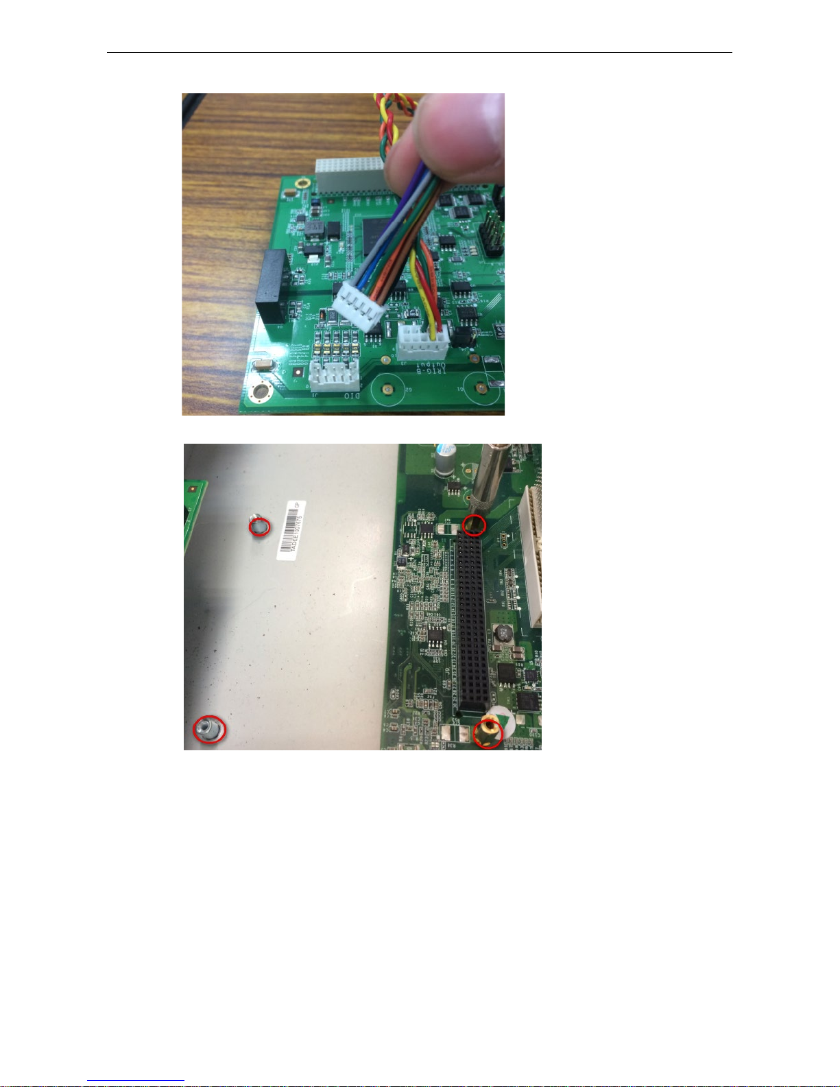
c. Connect the 10-wire DIO signal cable.
3. Install the fo ur 15 mm spacers on the embedded computer.
Page 12
DA-IRIGB-4DIO-PCI104-EMC4 Module Hardware Installation
4-5
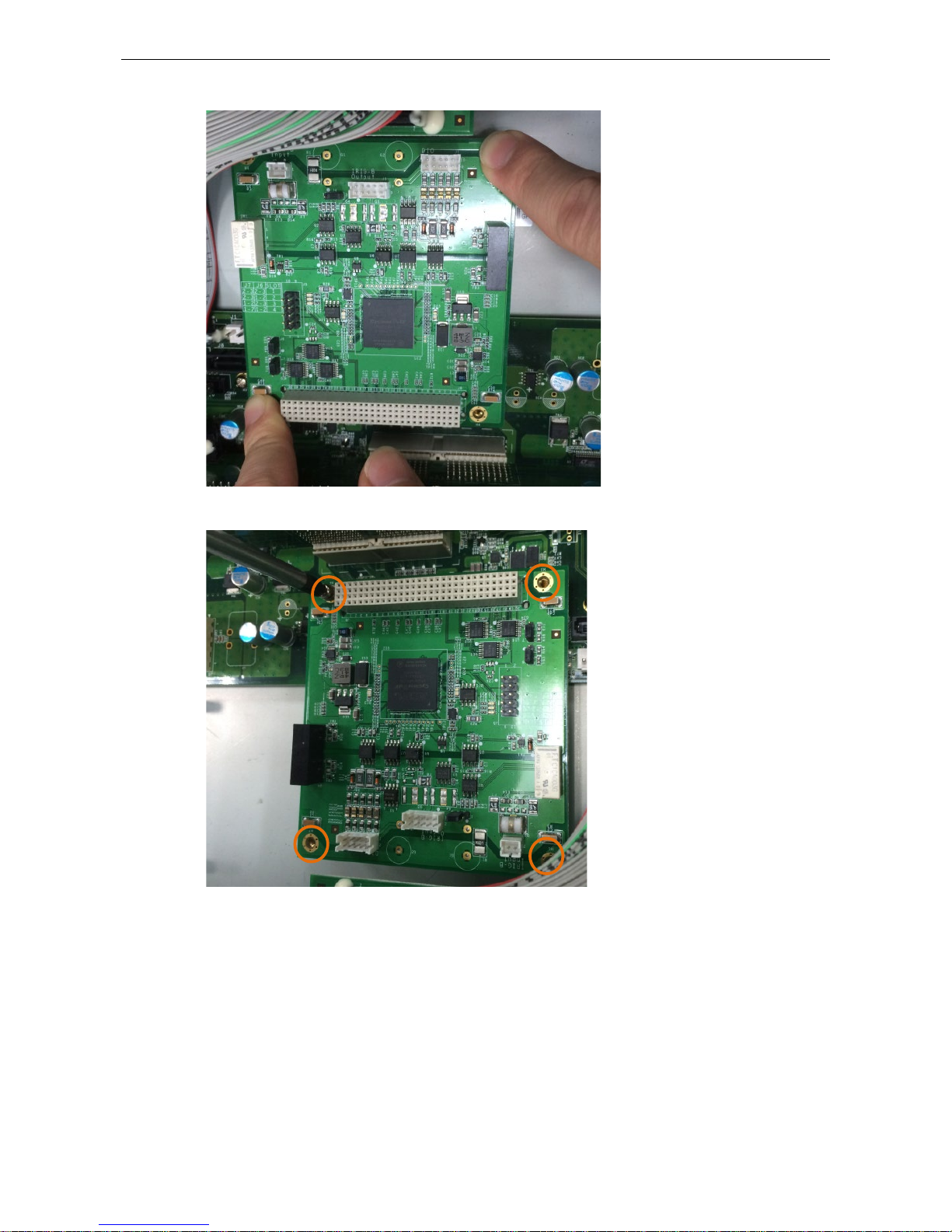
4. Insert the module firmly into an available PCI/104 slot.
5. Instal l the four screws to secure the module in place.
Page 13
DA-IRIGB-4DIO-PCI104-EMC4 Module Hardware Installation
4-6
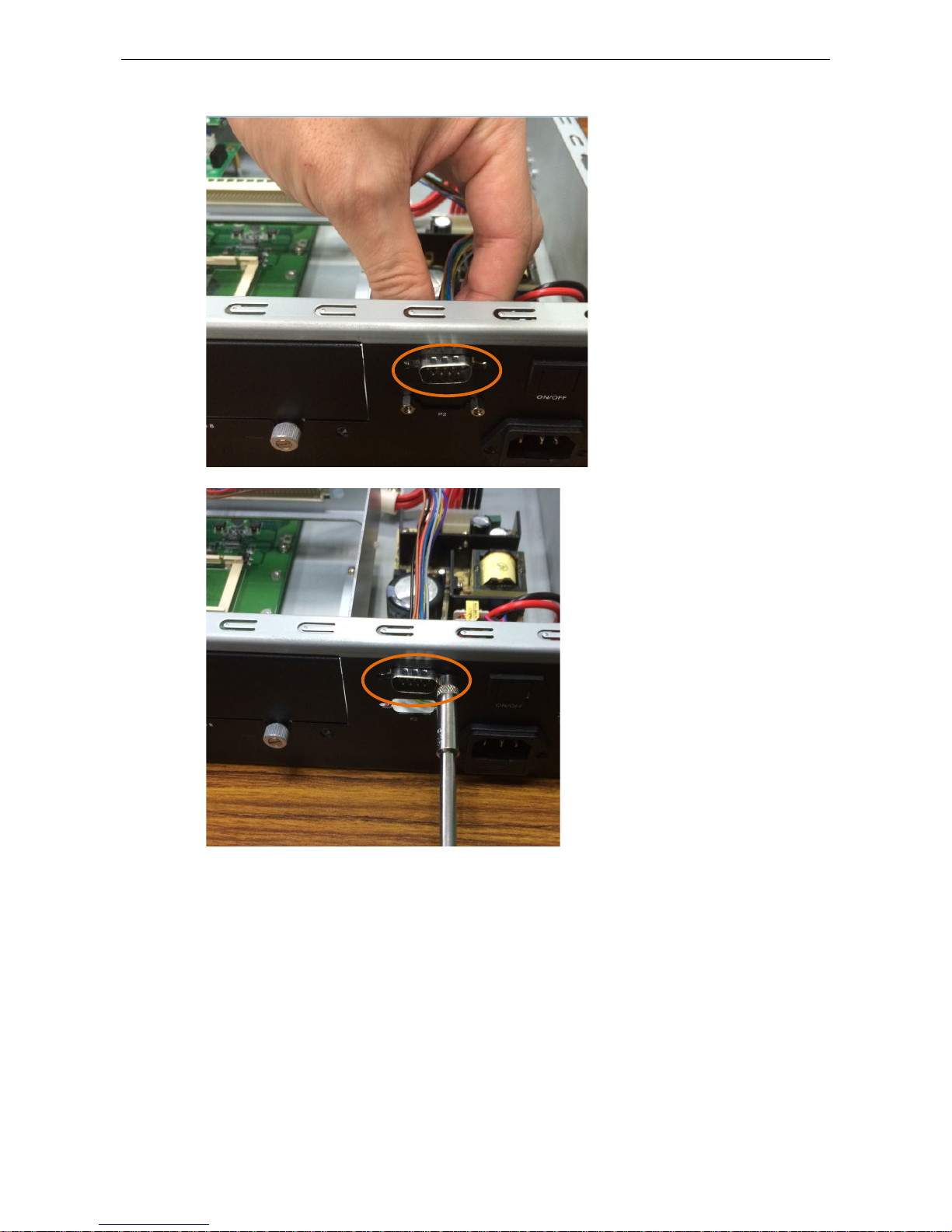
6. Secure the DB9 connectors on the rear panel of the embedded computer.
7. Turn on t he embedded computer. The BIOS will automatically set the IRQ and I/O address.
Page 14

3
3. Software Installation and Configuration
This chapter describes how to install driver and utility for the DA-IRIGB-4DIO-PCI104-EMC4 on an embedded
computer running Linux or Windows 7 (64-bit), and how to configure the software settings.
The following topic is covered in this chapter:
Installing the IRIG-B Driver in Linux
Online Installation
Off-line Installation
Using the timesync Daemon in Linux
Examples
Configuring the timesync Daemon
Using the IRIG-B Utility in Linux
Examples
Installing the IRIG-B Driver in Windows 7
Installing the IRIG-B Utility in Windows 7
Using the IRIG-B Utility in Windows 7
Configuring IRIG-B Parameters
Input Signal Type
IRIG-B Parity Mode
Configuring Time Synchronization Settings in Windows 7
Selecting a Time Input Source
Synchronizing with System Time
Configuring Digital Output and Input Status
Using the mxIrigUtil Command
Page 15

DA-IRIGB-4DIO-PCI104-EMC4 Module Software Installation and Configuration
4-2
Installing the IRIG-B Driver in Linux
NOTE
The driver for the DA-IRIGB-4DIO-PCI104-EMC4 module supports only Debian 7 Linux distribution (kernel
version 3.2.x).
Before you install the driver
in a different Linux distribution or kernel version, contact you r Moxa
sales representative for assistance .
You can install the Linux driver for the DA-IRIGB-4DIO-PCI104-EMC4 module on the embedded computer
using one of the following methods:
• Online from Moxa’s APT server
• Off-line
Online Installation
1. Make sur e that your embedded computer has access to the Internet.
2. If the unzip package is not installed on the computer, run the following c ommand the install it.
root@Moxa:~# sudo apt-get install unzip
3. Download Moxa’s Debian server public key (NEW-MOXA-SYS-DEBIAN-KEY) to the /home/ directory on your
target computer.
root@Moxa:~# sudo wget
http://www.moxa.com/drivers/UC/MOXA_SYS_DEB_KEY/MOXA-SYS-DEBIAN-KEY.zip
4. Unzip and I nstall Moxa’s public key file on the embedded computer (for example, DA-682A).
root@Moxa:~# sudo unzip MOXA-SYS-DEBIAN-KEY
root@Moxa:~# cd MOXA-SYS-DEBIAN-KEY
root@Moxa:~# sudo apt-key add NEW-MOXA-SYS-DEBIAN-KEY
5. In the /etc/apt/sources.list file, insert one of the following lines to add the Moxa APT server:
deb http://220.135.161.42/debian wheezy main
deb http://debian.moxa.com/debian wheezy main
The following figure shows an example.
root@Moxa:~# sudo vi /etc/apt/sources.list
...
# Add Moxa's apt server
deb http://220.135.161.42/debian wheezy main
6. Instal l the irigb package from Moxa' APT server. Complete the following steps:
a. Update the package list.
root@Moxa:~# sudo apt-get update
b. Check the irigb package.
root@Moxa:~# sudo apt-cache search irigb
da-682a-irigb-driver - Moxa DA-682A IRIG-B module device driver
da-682a-irigb-timesync-daemon - Moxa DA-682A IRIG-B time sync daemon
c. Install the IRIG-B driver and the timesync daemon. Follow the on-screen instruction. The following
figure shows the installation screen for the DA-682A.
root@Moxa:~# sudo apt-get install da-682a-irigb-timesync-daemon
Reading package lists... Done
Building dependency tree
Reading state information... Done
The following extra packages will be installed:
Page 16

DA-IRIGB-4DIO-PCI104-EMC4 Module Software Installation and Configuration
4-3
da-682a-irigb-driver
The following NEW packages will be installed:
da-682a-irigb-driver da-682a-irigb-timesync-daemon
0 upgraded, 2 newly installed, 0 to remove and 83 not upgraded.
Need to get 77.8 kB of archives.
After this operation, 0 B of additional disk space will be used.
Do you want to continue [Y/n]? Y
Get:1 http://220.135.161.42/debian/ wheezy/main da-682a-irigb-
driver amd64 1.1
[67.7 kB]
Get:2 http://220.135.161.42/debian/ wheezy/main da-682a-irigb-timesync-
daemon
amd64 1.2 [10.1 kB]
Fetched 77.8 kB in 0s (851 kB/s)
Selecting previously unselected package da-682a-irigb-driver.
(Reading database ... 31660 files and directories currently installed.)
Unpacking da-682a-irigb-driver
(from .../da-682a-irigb-driver_1.1_amd64.deb) ...
Selecting previously unselected package da-682a-irigb-timesync-daemon.
Unpacking da-682a-irigb-timesync-daemon
(from .../da-682a-irigb-timesync-daemon_1.2_amd64.deb) ...
Setting up da-682a-irigb-driver (1.1) ...
WARNING: -e needs -E or -F
Setting up da-682a-irigb-timesync-daemon (1.2) ...
6. Verify that the driver is loaded and the time sync daemon is running.
a. Use the
lsmod command to check whether the IRIG-B mod ule i s lo ad ed .
root@Moxa:~# lsmod|grep irig
moxa_irigb 12683 1
b. Verify that the timesync daemon is running with the default configuration.
root@Moxa:~# root@Moxa:~# ps aux|grep ServiceSyncTime
root 3078 0.0 0.1 16136 1140 ? S 10:43 0:00
/usr/sbin/ServiceSyncTime -t 1 -i 10 -B
Off-line Installation
1. Download the driver from the Moxa web site at http://www.moxa.com.
2. Upload or copy the following files to the embedded computer (for example, DA-682A):
• NEW-MOXA-SYS-DEBIAN-KEY
• DA-682A-irigb-driver-1.1_amd64.deb
• DA-682A-irigb_timesync_daemon_1.2_amd64.deb
3. Instal l Moxa’s public key file on the embedded computer (for example, DA-682A).
root@Moxa:~# sudo apt-key add NEW-MOXA-SYS-DEBIAN-KEY
4. Inst all the IRIG-B driver and the timesync daemon. Follow the on-screen instruction.
root@Moxa:/home/moxa/DebianServer# dpkg -i DA-682A-irigb-driver-1.1_amd64.deb
Selecting previously unselected package da-682a-irigb-driver.
(Reading database ... 31660 files and directories currently installed.)
Unpacking da-682a-irigb-driver (from DA-682A-irigb-driver-1.1_amd64.deb) ...
Setting up da-682a-irigb-driver (1.1) ...
root@Moxa:/home/moxa/DebianServer# dpkg -i
Page 17

DA-IRIGB-4DIO-PCI104-EMC4 Module Software Installation and Configuration
4-4
DA-682A-irigb_timesync_daemon_1.2_amd64.deb
Selecting previously unselected package da-682a-irigb-timesync-daemon.
(Reading database ... 31661 files and directories currently installed.)
Unpacking da-682a-irigb-timesync-daemon (from
DA-682A-irigb_timesync_daemon_1.2_amd64.deb) ...
Setting up da-682a-irigb-timesync-daemon (1.2) ...
5. Verify that the driver is loaded and the time sync daemon is running.
a. Use the
lsmod command to check whether the IRIG-B module is lo ad ed .
root@Moxa:~# lsmod|grep irig
moxa_irigb 12683 1
b. Verify that the timesync daemon is running with the default configuration.
root@Moxa:~# root@Moxa:~# ps aux|grep ServiceSyncTime
root 3078 0.0 0.1 16136 1140 ? S 10:43 0:00
/usr/sbin/ServiceSyncTime -t 1 -i 10 –B
Using the timesync Daemon in Linux
The following figure shows the help information of the timesync daemon.
root@Moxa:~# ServiceSyncTime -h
Found the IRIG-B module, Hardware ID = 1
IRIG-B time sync daemon.
Usage: ServiceSyncTime -t [signal type] -I -d -i [Time sync interval] -
p [Parity check
mode] -B
-t - [signal type]
0 - TTL
1 - DIFF
default value is 1
-I - inverse the input or output signal
-d - Disable time sync
Default this daemon enables the IRIG-B time sync from source port to system time.
-i - [Time sync interval] The time interval in seconds to sync the IRIG-
B time
into system time.
1 ~ 86400 Time sync interval. Default is 10 second.
-p - [Parity check mode] Set the parity bit
0: EVEN
1: ODD
2: NONE
default value is 0
-B - Run daemon in the background
Usage example: Enable to sync time from IRIG-
B Port 1, in TTL signal type every 10
seconds. The input is not inverse.
root@Moxa:~# ServiceSyncTime -t 0 -i 10
Page 18

DA-IRIGB-4DIO-PCI104-EMC4 Module Software Installation and Configuration
4-5
Examples
The following command example enables the daemon to synchronize time from P ort 1 in DIFF signal type every
10 seconds. The input signal is not inversed. The ServiceSyncTime process runs in the foreground.
root@Moxa:~# ServiceSyncTime -t 1 –i 10
The following command example enables the daemon to synchronize time from P ort 1 in DIFF signal type every
10 seconds with ODD parity check mode. The ServiceSyncTime process r uns in the foreground.
root@Moxa:~# ServiceSyncTime –t 1 -i 10 –p 1
The following command example enables the daemon to synchronize time from P ort 1 in DIFF signal type every
10 seconds and inverse the signal if t he cable cross-connect. The Service S yncTime process runs in the
foreground.
root@Moxa:~# ServiceSyncTime –t 1 -i 10 -I
Configuring the timesync Daemon
You can edit the /etc/init.d/mx_irigb.sh file to configure the timesync daemon. The script also includes the
default settings for MX_IRIGB_OPTS.
root@Moxa:~# sudo vi /etc/init.d/mx_irigb.sh
...
MX_IRIGB_SERVICESYNCTIME_OPTS="-t 1 -i 10 -B"
...
After you change the settings in the /etc/init.d/mx_irigb.sh file, restart the daemon.
root@Moxa:~# sudo service mx_irigb.sh restart
Using the IRIG-B Utility in Linux
The mxIrigUtil command is available in the destination folder that you selected during the installation process.
The list of available parameters and options for the mxIrigUtil command is the same in Linux and Windows 7.
The following figure shows the help information for the IRIG-B utility.
root@Moxa:~# mxIrigUtil -h
Get/set Moxa DA-IRIGB utility
Usage: mxIrigUtil -f function_id [-p parameters] [-c] [-h]
Show the utility information if no argument apply.
-h: Show this information.
-c: Indicate the n-the IRIG-B Card.
-f: Pass function id argument to execute specify functionality
-p: Parameters for each function, use comma to pass multiple variable
For example: Set IRIG-B RTC Time 2014/01/01 03:25:00
mxIrigUtil -f 2 -p 2014,1,1,3,25,0
Function description list:
0:Get Hardware ID
1:Get IRIG-B RTC Time
Page 19

DA-IRIGB-4DIO-PCI104-EMC4 Module Software Installation and Configuration
4-6
2:Set IRIG-B RTC Time
-p [2000-2099],[1-12],[1-31],[0-23],[0-59],[0-59]
(year[2000-2099],month[1-12],day[1-31],hour[0-23],min[0-59],sec[0-59]); default
value is 2014,01,01,00,00,00
3:Get IRIG-B RTC Sync. Source
4:Set IRIG-B RTC Sync. Source
-p [0-2] (Source: 0=FreeRun In (Internal RTC), 1=Fiber In, 2=Port 1 In)
;
default value is 2
5:Get IRIG-B Signal Status
-p [1-2] (Source: 1=Fiber In, 2=Port 1 In); default value is 2
6:Get IRIG-B Input Parity Check Mode
-p Source[1-2] (1=Fiber In, 2=Port 1 In); default value is 2
7:Set IRIG-B Input Parity Check Mode
-p Source[1-2] (1=Fiber In, 2=Port 1 In),Mode[0-
2] (0=Even, 1=Odd, 2=None);
default value is 2,0
8:Get IRIG-B Output Parity Check Mode
9:Set IRIG-B Output Parity Check Mode
-p Mode[0-1] (0=Even, 1=Odd); default value is 0
10:Get Pulse per second width(ms)
11:Set Pulse per second width(ms)
-p [0-999] (width: 0-999 ms); default value is 0
12:Get input signal type
-p [0-1] 0=Fiber, 1=Port 1 (port[0-1]); default value is 1
13:Set input signal type
-p [0-1],[0-1],[0-1]
(port[0-1]: 0=Fiber 1=Port 1,
signal type[0-1]: 0=TTL, 1=DIFF,
inverse[0-1]: 0=No inverse 1=Inverse)
default value is 1,1,0
14:Get output signal type
-p [1-4] (output port[1-4]); default value is 1
15:Set output signal type
-p [1-4],[0-1],[0-3],[0-1]
(output port[1-4]: Output port 1-4,
signal type[0-1]: 0=TTL, 1=DIFF,
mode[0-3]: 0=From Fiber Input Port, 1=From Port 1 Input, 2=From
IRIG-B encode(Internal RTC), 3=From PPS encode;
inverse[0-1]: 0=No inverse, 1=Inverse)
default value is 1,1,2,0
16:Get Digital Output
-p [0-3] (digital output port[0-3]); default value is 0
17:Set Digital Output
-p [0-3],[0-1] (digital output port[0-3],level[0-1]); default value is 0,0
18:Get Digital Input
-p [0-2] (digital input port[0-2]); default value is 0
Page 20

DA-IRIGB-4DIO-PCI104-EMC4 Module Software Installation and Configuration
4-7
The following table describes the function IDs.
Function ID Function description Parameters
0 Display the hardware device ID. For example,
Hardware ID = 1 (DA_IRIGB_4DIO_PCI104)
N/A
1 Display current intern al RTC time.
N/A
2 Set internal RTC time yyyy,MM,dd,hh,mm,ss
Where
yyyy is the year (2000 – 2099).
MM is the month (1-12).
dd is the day of the month (1-31).
hh is the hour of the day (0 -23).
mm is the minute (0-59).
ss is the second (0-59).
3 Display the RTC synchronization source. N/A
4 Set the RTC synchronization source . Source [0|2]
Where
0 is free run.
2 is port 1 input.
5 Display IRIG-B signal status.
Possible status are:
0–Normal
1–Off Line
2–Frame Error
3–Parity Error
Source [2]
Where
2 is port 1 input.
6 Display IRIG-B input parity check mode.
Possible modes are:
0–Even
1-Odd
2-None
Source [2]
Where
2 is port 1 input.
7 Set IRIG-B input parity check mode Source, Mode
Where
Source: 2 (port 1 input)
Mode: 0 (Even), 1 (Odd), 2 (None)
10 Display pulse per second width (ms). N/A
11 Set pulse per second width (ms). Width (0~999)
12 Display input signal type. port [0|1]
Where
1 is port 1 input.
13 Set input signal type. port, signal type, mode, inv e rse
Where
port – 1 is “Port 1”
signal type – 0 is TTL; 1 is “DIFF”
inverse – 0 means do not inverse; 1 means
inverse.
16 Display digital output. port
where 0 is “DO0”, 1 is “DO1”, 2 is “DO2”, and
3 is “DO3”
17 Set digital output. port, level
Where
port –
0 is “DO0”, 1 is “DO1”, 2 is “DO2”, and
3 is “DO3”
level – 0 is low and 1 is hi gh
Page 21

DA-IRIGB-4DIO-PCI104-EMC4 Module Software Installation and Configuration
4-8
Function ID Function description Parameters
18 Display digital input. port
Where 0 is “DI0”, 1 is “DI1”, and 2 is “DI2”
NOTE
Function
IDs 8, 9, 14, and 15 are not available for the DA-IRGB-4DIO-PCI-104-
EMC4 module, which does not
support the f
iber input port.
Examples
The following command example displays the IRIG-B module hardware ID.
root@Moxa:~# mxIrigUtil -f 0
Get Hardware ID = 1 (DA_IRIGB_4DIO_PCI104)
The following command example displays the IRIG-B module internal RTC time.
root@Moxa:~# mxIrigUtil -f 1
Get IRIGB RTC = 2011/11/11 17:29:55.204137520, TZ = +8, TQ = 6
The following command example sets t h e IRIG-B module internal RTC time to 2014/11/19 11:19:50.
root@Moxa:~# mxIrigUtil -f 2 -p 2014,11,19,11,19,50
Set IRIGB RTC = 2014/11/19 11:19:50
The following command example displays the IRIG-B module time sync source setting. In this example, the
time source is IRIG-B Port 1.
root@Moxa:~# mxIrigUtil -f 3
Get Sync. Source = 2 (Port 1 In)
The following command example sets t h e IRIG-B module time sync source.
root@Moxa:~# mxIrigUtil -f 4 -p 1
Set Sync. Source = 1
The following command displays the IRIG-B signal status.
root@Moxa:~# mxIrigUtil -f 5 -p 1
Fiber In Signal Status = 1(Off Line)
root@Moxa:~# mxIrigUtil -f 5 -p 2
Port 1 In Signal Status = 2(Frame Error)
root@Moxa:~
The following command displays the pulse per second width (ms).
root@Moxa:~# mxIrigUtil -f 10
Get PPS Width = 0 ms
The following command example sets t h e pulse per second width (ms).
root@Moxa:~# mxIrigUtil -f 11 -p 5
Set PPS Width = 5 ms
The following command example displays the input interface.
root@Moxa:~# mxIrigUtil -f 12 -p 1
Get Input Port 1 Interface = 1(DIFFERENTIAL), Inverse = 0
Page 22

DA-IRIGB-4DIO-PCI104-EMC4 Module Software Installation and Configuration
4-9
The following command example displays the digital output interface.
root@Moxa:~# mxIrigUtil -f 16 -p 0
Get DO 0 = 1
root@Moxa:~# mxIrigUtil -f 16 -p 1
Get DO 1 = 1
root@Moxa:~# mxIrigUtil -f 16 -p 2
Get DO 2 = 1
root@Moxa:~# mxIrigUtil -f 16 -p 3
Get DO 3 = 1
root@Moxa:~# mxIrigUtil -f 16 -p 4
Get DO 4 = 1
The following command example sets t h e digital output interface.
root@Moxa:~# mxIrigUtil -f 17 -p 0,0
Set DO 0 = 0
root@Moxa:~# mxIrigUtil -f 17 -p 0,1
Set DO 0 = 1
root@Moxa:~# mxIrigUtil -f 17 -p 1,0
Set DO 1 = 0
root@Moxa:~# mxIrigUtil -f 17 -p 1,1
Set DO 1 = 1
root@Moxa:~# mxIrigUtil -f 17 -p 2,0
Set DO 2 = 0
root@Moxa:~# mxIrigUtil -f 17 -p 2,1
Set DO 2 = 1
root@Moxa:~# mxIrigUtil -f 17 -p 3,0
Set DO 3 = 0
root@Moxa:~# mxIrigUtil -f 17 -p 3,1
Set DO 3 = 1
The following command example displays the digital input interface.
root@Moxa:~# mxIrigUtil -f 18 -p 0
Get DI 0 = 0
root@Moxa:~# mxIrigUtil -f 18 -p 1
Get DI 1 = 0
root@Moxa:~# mxIrigUtil -f 18 -p 2
Get DI 2 = 0
You can edit the /etc/init.d/mx_irigb.sh script to configure the IRIG-B utility. For example, if you want to
set the IRIG-B digital output interface, remove the ‘#’ symbol from the
/usr/sbin/mxIrigUtil line and
configure the
MX_IRIGB_UTIL_OPTS parameter. The following figure shows an example.
root@Moxa:~# sudo vi /etc/init.d/mx_irigb.sh
...
MX_IRIGB_UTIL_OPTS=" -f 15 -p 1,1,2,0"
...
case "$1" in
start)
...
Page 23

DA-IRIGB-4DIO-PCI104-EMC4 Module Software Installation and Configuration
4-10
# If you need the IRIG-B signal output, you should remove the # in from of
the following line.
/usr/sbin/mxIrigUtil $MX_IRIGB_UTIL_OPTS > /dev/null 2>&1
...
Installing the IRIG-B Driver in Windows 7
1. Log into the embedded computer as a n a dministrator.
2. Download the installation files fro m th e Moxa web site at http://www.moxa.com
.
3. Copy the dr iver and utility files to the embedded computer.
4. Double-click the IRIG-B driver installation file.
5. When the welcome screen appears, click Next.
Page 24

DA-IRIGB-4DIO-PCI104-EMC4 Module Software Installation and Configuration
4-11
6. Select install for anyone using this computer and click Next.
NOTE
Before you select
Install just for me, make sure that you understan d how this option might affect the
operation for other users on the embedded computer.
7. Accept the default destination folder or click Browse to select one; then, click Install.
Page 25

DA-IRIGB-4DIO-PCI104-EMC4 Module Software Installation and Configuration
4-12
8. When the installation process is complete , click Finish.
Installing the IRIG-B Utility in Windows 7
You can use the IRIG-B utility to view the status information and configure the signal typ e for the
DA-IRIGB-4DIO-PCI104 module.
NOTE
Before
you install the utility in 64-bit Windows 7, make sure that Microsoft Visual C++ 2010 SP1
Redistributable Package and Microsoft Visual C++ 2010 SP1 Redistributable Package (x64)
are already
i
nstalled.
1. Log into the embedded computer as a n a dministrator.
2. Obtain the utility installation file from the Moxa web site at http://www.moxa.com
.
3. On the embedded computer, double-click t h e IRIG-B utility installation file.
Page 26

DA-IRIGB-4DIO-PCI104-EMC4 Module Software Installation and Configuration
4-13
4. When the welcome screen appears, click Next.
5. Select install for anyone using this computer and click Next.
NOTE
Before you select
Install just for me, make sure that you understan d how this option might affect the
operation for other users o
n the embedded computer.
Page 27

DA-IRIGB-4DIO-PCI104-EMC4 Module Software Installation and Configuration
4-14
6. Accept the default destination folder or cli ck Browse to select one; then, click Install.
7. When the installation process is complete , click Finish.
Page 28

DA-IRIGB-4DIO-PCI104-EMC4 Module Software Installation and Configuration
4-15
Using the IRIG-B Utility in Windows 7
After you install the IRIG-B utility on your embedded computer running Windows 7, you start the IRIG-B
utility from the start menu (click Moxa
DA-IRIG-B Utility mxIrigbCardConf) to configure the
DA-IRIGB-4DIO-PCI104-EMC4.
Page 29

DA-IRIGB-4DIO-PCI104-EMC4 Module Software Installation and Configuration
4-16
Configuring IRIG-B Parameters
You can use the IRIG-B utility to configure the IRIG-B parameters that the DA-IRIGB-4DIO-PCI104-EMC4
module supports.
Input Signal Type
In the Moxa IRIG-B Card Configure Utility screen, select Differential or TTL from the Signal Type drop-down
list. Click Apply to make the changes take effect.
Page 30

DA-IRIGB-4DIO-PCI104-EMC4 Module Software Installation and Configuration
4-17
IRIG-B Parity Mode
Depending on your country, you may need to configure the parity mode.
From the IRIG-B Parity Mode drop-down list box, select an option. For example, in China, select Odd charity
mode.
Page 31

DA-IRIGB-4DIO-PCI104-EMC4 Module Software Installation and Configuration
4-18
Configuring Time Synchronization Settings i n
Windows 7
In the IRIG-B utility, you can set the DA-IRIGB-4DIO-PCI104-EMC4 module to synchronize the RTC using one
of the following time input sources:
• External IRIG-B signal
• Internal independent 25 MHz reference clock
Selecting a Time Input Source
From the Sync. to internal RTC Source drop-down list, select a time input source that you want to use.
Synchronizing with System Time
You can synchronize the RTC time with the system time. In the IRIG-B utility, select the Sync. internal RTC
to system time check box and enter the number of seconds to synchronize the time (the default is 10
seconds).
Page 32

DA-IRIGB-4DIO-PCI104-EMC4 Module Software Installation and Configuration
4-19
Configuring Digital Output and Input Status
The DA-IRIGB-4DIO-PCI104-EMC4 module features four digital outputs and three digital inputs. You can use
IRIG-B utility configur e the digital output and d igi tal in p ut sta tu s .
To control a digital output, select or clear the associated check box. The following table shows the signal and
logic state for the check box.
Check box Signal Logic
Selected High 1
Not selected Low 0
To read status from a digital input, select or clear the associated check box. The following table shows the
signal and logic state.
Check box Signal Logic
Selected High 1
Not selected Low 0
Page 33

DA-IRIGB-4DIO-PCI104-EMC4 Module Software Installation and Configuration
4-20
Using the mxIrigUtil Command
The mxIrigUtil command is available in the destination folder that you selection during the installation process.
The list of available parameters and options for the mxIrigUtil command is the same in Linux and Windows 7.
To display the help information, in a command line w indow, enter the mxIrigUtil co mmand without a
parameter.
Usage: mxIrigUtil -f function_id [-p parameters] [-c] [-h]
Show the utility information if no argument apply.
-h: Show this information.
-c: Indicate the n-the IRIG-B Card.
-f: Pass function id argument to execute specific functionality.
-p: Parameters for each function, use comma to pass multiple variable
The following table describes the function IDs.
Function ID Function description Parameters
0 Display the hardware device ID. For example,
Hardware ID = 1 (DA_IRIGB_4DIO_PCI104)
N/A
1 Display current intern al RTC time.
N/A
2 Set internal RTC time yyyy,MM,dd,hh,mm,ss
Where
yyyy is the year (2000 – 2099).
MM is the month (1-12).
dd is the day of the month (1-31).
hh is the hour of the day (0 -23).
mm is the minute (0-59).
ss is the second (0-59).
3 Display the RTC synchronization source. N/A
4 Set the RTC synchronization source. Source [0|2]
Where
0 is free run.
2 is port 1 input.
5 Display IRIG-B signal status.
Possible status are:
0–Normal
1–Off Line
2–Frame Error
3–Parity Error
Source [2]
Where
2 is port 1 input.
6 Display IRIG-B input pari ty check mode.
Possible modes are:
0–Even
1-Odd
2-None
Source [2]
Where
2 is port 1 input.
7 Set IRIG-B input parity check mode Source, Mode
Where
Source: 2 (port 1 input)
Mode: 0 (Even), 1 (Odd), 2 (None)
10 Display pulse per second width (ms). N/A
11 Set pulse per second width (ms). Width (0~999)
Page 34

DA-IRIGB-4DIO-PCI104-EMC4 Module Software Installation and Configuration
4-21
Function ID Function description Parameters
12 Display input signal type. port [0|1]
Where
1 is port 1 input.
13 Set input signal type. port, signal type, mode, inverse
Where
port – 1 is “Port 1”
signal type – 0 is TTL; 1 is “DIFF”
inverse – 0 means do not inverse; 1 means
inverse.
16 Display digital output. port
where 0 is “DO0”, 1 is “DO1”, 2 is “DO2”,
and 3 is “DO3”
17 Set digital output. port, level
Where
port – 0 is “DO0”, 1 is “DO1”, 2 is “ DO2”,
and 3 is “DO3”
level – 0 is low and 1 is h igh
18 Display digital input. port
Where 0 is “DI0”, 1 is “DI1”, and 2 is “DI2”
NOTE
Function
IDs 8, 9, 14, and 15 are not available for the DA-IRGB-4DIO-PCI-104-
EMC4 module, which does not
support the f
iber input port.
For example, if you want to set the IRIG-B RTC time to 2014/01/01 03:25:00, enter the followin g comm and.
mxIrigUtil -f 2 -p 2014,1,1,3,25,0
Page 35

4
4. API Reference
This chapter describes the available APIs that you can use to develop your own time synchronization and digital
input/digital output control applications.
The following topics are covered in this chapter:
Get IRIG-B Board Hardware ID
Open IRIG-B Device
Close IRIG-B Device
Get Digital Input Signal
Get Digital Output Signal
Get IRIG-B Parity Check Mode
Get Input Interface
Get IRIG-B Output Parity Check Mode
Get Output Interface
Get Pule Per Second Output Width
Get IRIG-B Signal Status
GET RTC Synchronization Source
Get RTC from IRIG-B Device
Set Digital Output Signal
Set IRIG-B Input Parity Check Mode
Set Input Interface
Set IRIG-B Output Parity Check Mode
Set Output Interface
Set Pulse Per Second Output Width
Set RTC Synchronization Source
Set RTC to IRIG-B Device
Synchronize System Local Time with IRIG RTC
IRIG-B Program Example
Page 36

DA-IRIGB-4DIO-PCI104-EMC4 Module API Reference
4-2
Get IRIG-B Board Hardware ID
MXIRIG_API BOOL mxIrigbGetHardwareID (HANDLE hDev, PDWORD pdwHwId)
Parameters
in hDev The handle for value returned from the mxIrigbOpen funct ion.
out pdwHwId The pointer for the hardware ID
Returns
If the operation completes successfully, the return value is nonzero. If the operation fails or is pending, the
return value is zero. To display detailed error information, use GetLastError.
Open IRIG-B Device
MXIRIG_API HANDLE mxIrigbOpen (int index)
Parameters
in index The device number (starting from 0).
Returns
Returns the pointer to the device handle. A return value is of -1 indicates a f a ilure.
Close IRIG-B Device
MXIRIG_API void mxIrigbClose (HANDLE hDev)
Parameters
in hDev A valid handle value returned from the mxIrigbOpen function.
Returns
None.
Get Digital Input Signal
MXIRIG_API BOOL mxI rigbGetDigitalInputSignal (HANDLE hDev, DWORD dwPo rt, PDWORD pValue)
Parameters
in hDev A valid handle value returned from the mxIrigbOpen function.
in dwPort The port number (starting from 0).
out pValue The port data (1:HIGH, 0:LOW).
Page 37

DA-IRIGB-4DIO-PCI104-EMC4 Module API Reference
4-3
Returns
If the operation completes successfully, the return value is nonzero. If the operation fails or is pending, the
return value is zero. To display detailed error information, use GetLastError.
Get Digital Output Signal
MXIRIG_API BOOL mxIrigbGetDigitalOutputSignal (HANDLE hDev, DWORD dwPort, PD WORD pValue)
Parameters
in hDev A valid handle value returned from the mxIrigbOpen function.
in dwPort The port number (starting from 0).
out pValue A pointer to get port data (1:HIGH, 0:LOW).
Returns
If the operation completes successfully, the return value is nonzero. If the operation fails or is pending, the
return value is zero. To display detailed error information, call GetLastError.
Get IRIG-B Parity Check Mode
MXIRIG_API BOOL mxIrigbGetInputParityCheckMode (HANDLE hDev, DWORD dwSource, PDWORD
pdwMode)
Parameters
in hDev A valid handle value returned from the mxIrigbOpen function.
in dwSource The value is one of RTC_SYNC_SOURCE, but cannot be
TIMESRC_FREERUN.
out pdwMode A pointer to get output parity check mode. The value is one of
PARITY_CHECK_MODE .
Returns
If the operation completes successfully, the return value is nonzero. If the operation fails or is pending, the
return value is zero. To display detailed error information, use GetLastError.
Get Input Interface
MXIRIG_API BOOL mxIrigbGetInputSignalType (HANDLE hDev, DWORD dwPort, PDWORD pdwType,
PBOOL pbInvert)
Parameters
in hDev A valid handle value returned from the mxIrigbOpen function.
in dwPort Signal source. The value is one of PORT_LIST.
out pdwType A pointer to get the signal type. The value is one of SIGNAL_TYPE.
out pbInvert A pointer to get the signal mode. If the value is not zero, the signal is
Page 38

DA-IRIGB-4DIO-PCI104-EMC4 Module API Reference
4-4
inversed.
Returns
If the operation completes successfully, the return value is nonzero. If the operation fails or is pending, the
return value is zero. To display detailed error information, use GetLastError.
Get IRIG-B Output Parity Check Mode
MXIRIG_API B OOL mxIrigbGetOutputParityCheckMode (HANDLE hDev, PDWORD pdwMode)
Parameters
in hDev A valid handle value returned from the mxIrigbOpen function.
out pdwMode A pointer to get the output parity check mode.
Returns
If the operation completes successfully, the return value is nonzero. If the operation fails or is pending, the
return value is zero. To display detailed error information, use GetLastError.
Get Output Interface
MXIRIG_API BOOL mxIrigbGetOutputSignalType (HANDLE hDev, DWORD dwPort, PDWORD pdwType,
PDWORD pdwMode, PBOOL pbInvert)
Parameters
in hDev A valid handle value returned from the mxIrigbOpen function.
in dwPort Signal source. The value is one of PORT_LIST.
out pdwType A pointer to get the signal type. Th e va lue is one of SIGNAL_TYPE.
out pdwMode A pointer to get the signa l output mode. The value is one of
OUTPUT_MODE .
out pbInvert A pointer to get the signal mode. If the value is not zero, the signal is
inversed.
Returns
If the operation completes successfully, the return value is nonzero. If the operation fails or is pending, the
return value is zero. To display detailed error information, use GetLastError.
Get Pule Per Second Output Width
MXIRIG_API B OOL mxIrigbGetPpsWidth (HANDLE hDev, PDWOR D pdwMilliSecond)
Parameters
in hDev A valid handle value returned from the mxIrigbOpen function.
out pdwMilliSecond A pointer to get the pulse width per millisecond value.
Page 39

DA-IRIGB-4DIO-PCI104-EMC4 Module API Reference
4-5
Returns
If the operation completes successfully, the return value is nonzero. If the operation fails or is pending, the
return value is zero. To display detailed error information, use GetLastError.
Get IRIG-B Signal Status
MXIRIG_API BOOL mxIrigbGetSignalStatus (HANDLE hDev, DWORD dwSource, PDWORD pdwStatus)
Parameters
in hDev A valid handle value returned from the mxIrigbOpen function.
in dwSource The IRIGB signal source. The value is one of PORT_L I S T.
out dwStatus A pointer to get IRIGB signal status. The value is one of
IRIG_SIGNAL_STATUS.
Returns
If the operation completes successfully, the return value is nonzero. If the operation fails or is pending, the
return value is zero. To display detailed error information, use GetLastError.
GET RTC Synchronization Source
MXIRIG_API BOOL mxIrigbGetSyncTimeSrc (HANDLE hDev, PDWORD pdwSource)
Parameters
in hDev A valid handle value returned from the mxIrigbOpen function.
out pdwSource A pointer to get internal RTC synchronization source. The value is one of
RTC_SYNC_SOURCE.
Returns
If the operation completes successfully, the return value is nonzero. If the operation fails or is pending, the
return value is zero. To display detailed error information, use GetLastError.
Get RTC from IRIG-B Device
MXIRIG_API B OOL mxIrigbGetTime (HANDLE hDev, PRTCTIME p RtcTime)
Parameters
in hDev A valid handle value returned from the mxIrigbOpen function.
out pRtcTime A pointer to a PRTCTIME struc ture that contains the time va lu e.
Returns
If the operation completes successfully, the return value is nonzero. If the operation fails or is pending, the
return value is zero. To display detailed error information, use GetLastError.
Page 40

DA-IRIGB-4DIO-PCI104-EMC4 Module API Reference
4-6
Set Digital Output Signal
MXIRIG_API BOOL mxI rigbSetDigitalOutputSignal (HANDLE hDev, DWORD dwPor t, DWORD value)
Parameters
in hDev A valid handle value returned from the mxIrigbOpen function.
in dwPort The port number (starting from 0).
in value The port data (1:HIGH, 0:LOW).
Returns
If the operation completes successfully, the return value is nonzero. If the operation fails or is pending, the
return value is zero. To display detailed error information, use GetLastError.
Set IRIG-B Input Parity Check Mode
MXIRIG_API B OOL mxIrigbSetInputParityCheckMode (HANDLE hDev, DWORD dwSource, DWORD
dwMode)
Parameters
in hDev A valid handle value returned from the mxIrigbOpen function.
in dwSource The value is one of RTC_SYNC_SOURCE, but cannot be
TIMESRC_FREERUN.
in dwMode PARITY_CHECK_MODE to set parity check mode.
Returns
If the operation completes successfully, the return value is nonzero. If the operation fails or is pending, the
return value is zero. To display detailed error information, use GetLastError.
Set Input Interface
MXIRIG_API BOOL mxIrigbSetInputSignalType (HAN DLE hDev, DWORD dwPort, DWORD dwType, BOOL
invert)
Parameters
in hDev A valid handle value returned from the mxIrigbOpen function.
in dwPort Signal source. The value is one of PORT_LIST.
in dwType SIGNAL_TYPE to set the input interface mode.
in invert If the value is not zero, invert the input signal.
Returns
If the operation completes succe ssfully, the return value is nonzero. If the operation fails or is pending, the
return value is zero. To display detailed error information, use GetLastError.
Page 41

DA-IRIGB-4DIO-PCI104-EMC4 Module API Reference
4-7
Set IRIG-B Output Parity Check Mode
MXIRIG_API BOOL mxIrigbSetOutputParityCheckMode (HANDLE hDev, DWORD dwMode)
Parameters
in hDev A valid handle value returned from the mxIrigbOpen function.
in dwMode PARITY_CHECK_MODE to set the parity check mode.
Returns
If the operation completes successfully, the return value is nonzero. If the operation fails or is pending, the
return value is zero. To display detailed error information, use GetLastError.
Set Output Interface
MXIRIG_API BOOL mxIrigbSetOutputSignalType (HANDLE hDev, DWORD dwPort, DWORD dwType,
DWORD dwMode, BOOL invert)
Parameters
in hDev A valid handle value returned from the mxIrigbOpen function.
in dwPort Signal source. The value is one of PORT_LIST.
in dwType SIGNAL_TYPE to set the input interface mode.
in dwMode OUTPUT_MODE to set the outpu t interface mode.
in invert If the value is not zero, invert the input signal.
Returns
If the operation completes successfully, the return value is nonzero. If the operation f a ils or is pending, the
return value is zero. To display detailed error information, use GetLastError.
Set Pulse Per Second Output Width
MXIRIG_API BOOL mxI rigbSetPpsWidth (H ANDLE hDev, DWORD dwM illiSecond)
Parameters
in hDev A valid handle value returned from the mxIrigbOpen function.
in dwMilliSecond The pulse width per millisecond.
Returns
If the operation completes successfully, the return value is nonzero. If the operation f a ils or is pending, the
return value is zero. To display detailed error information, use GetLastError.
Set RTC Synchronization Source
MXIRIG_API BOOL mxIrigbSetSyncTimeSrc (HANDLE hDev, DWORD dwSource)
Page 42

DA-IRIGB-4DIO-PCI104-EMC4 Module API Reference
4-8
Parameters
in hDev A valid handle value returned from the mxIrigbOpen function.
in dwSource RTC_SYNC_SOURCE to select the RTC synchro niz a tion source.
Returns
If the operation completes successfully, the return value is nonzero. If the operation fails or is pending, the
return value is zero. To display detailed error information, use GetLastError.
Set RTC to IRIG-B Device
MXIRIG_API B OOL mxIrigbSetTime (HANDLE hDev, PRTCTIME pR tcTime)
Parameters
in hDev A valid handle value returned from the mxIrigbOpen function.
in pRtcTime The pointer to a PRTCTIME structure that contains the time value.
Returns
If the operation completes successfully, the return value is nonzero. If the operation fails or is pending, the
return value is zero. To display detailed error information, use GetLastError.
Synchronize System Local Time with IRIG RTC
MXIRIG_API BOOL mxIrigbSyncTime (HANDLE hDev, BOOL bToFrom)
Parameters
in hDev A valid handle value returned from the mxIrigbOpen function.
in pRtbToFrom 0: Sets IRIG RTC to Local Time
1: Sets Local Time to IRIG RTC
Returns
If the operation completes successfully, the return value is nonzero. If the operation fails or is pending, the
return value is zero. To display detailed error information, use GetLastError.
IRIG-B Program Example
To develop an IRIG-B program, follow the procedure listed in the program example.
/* 1. Include the header files */
#include “Public.h”
#include “mxirig.h”
/* 2. open the IRIG-B device by mxIrigbOpen(); */
Page 43

DA-IRIGB-4DIO-PCI104-EMC4 Module API Reference
4-9
HANDLE irigbCardHandle;
irigbCardHandle = mxIrigbOpen(0);
if( irigbCardHandle < 0 ) {
fprintf(stderr,"mxIrigbOpen() fail!\n");
return 0;
}
/* 3.1. Reference the IRIG-B API to control the IRIG-B module. EX: set the sync time
source */
if (!mxIrigbSetSyncTimeSrc(irigbCardHandle, time_source) ) {
printf("Set sync source fail\n");
mxIrigbClose(irigbCardHandle);
return 0;
}
/* 3.2. Reference the IRIG-B API to control the IRIG-B module. EX: Configure IRIG-B
input signal type. */
if(!mxIrigbSetInputInterface(irigbCardHandle, time_source_interface, signal_type,
inverse)) {
fprintf(stderr, "mxIrigbSetInputInterface() fail\n");
mxIrigbClose(irigbCardHandle);
return 0;
}
/*3.3. Reference the IRIG-B API to control the IRIG-B module. EX: Set Sync Time Source
*/
if(!mxIrigbSetSyncTimeSrc(irigbCardHandle, time_source)) {
fprintf(stderr,"mxIrigbSetSyncTimeSrc() time_source:%d fail\n", time_source);
mxIrigbClose(irigbCardHandle);
return 0;
}
/* …To do in your IRIG-B program … */
/* 4. Finally remember to close the IRIG-B device */
mxIrigbClose(irigbCardHandle);
For more information about creating an IRIG-B program, refer to the released code examples (such as
ServiceSyncTime.cpp, unites.cpp, or mxIrigUtil.cpp ).
Page 44

DA-IRIGB-4DIO-PCI104-EMC4 Module API Reference
4-10
 Loading...