

Moxa Technologies DA-820C-KLXL-H-T, DA-820C-KL3-HH-T, DA-820C-KL7-H, DA-820C-KLXM-H, DA-820C-KL7-HH User Manual
...Page 1

DA-820C Series Embedded Computer
User’s Manual
Version 1.0, August 2019
www.moxa.com/product
© 2019 Moxa Inc. All rights reserved.
Page 2

DA-820C Series Embedded Computer
Moxa Americas
Toll
Tel:
Fax:
Moxa China (Shanghai office)
Toll
Tel:
Fax:
Moxa Europe
Tel:
Fax:
Moxa Asia
Tel:
Fax:
Moxa India
Tel:
Fax:
User’s Manual
The software described in this manual is furnished under a license agreement and may be used only in accordance with
the terms of that agreement.
Copyright Notice
© 2019 Moxa Inc. All rights reserved.
Trademarks
The MOXA logo is a registered trademark of Moxa Inc.
All other trademarks or registered marks in this manual belong to their respective manufacturers.
Disclaimer
Information in this document is subject to change without notice and does not represent a commitment on the part of
Moxa.
Moxa provides this document as is, without warranty of any kind, either expressed or implied, including, but not limited
to, its particular purpose. Moxa reserves the right to make improvements and/or changes to this manual, or to the
products and/or the programs described in this manual, at any time.
Information provided in this manual is intended to be accurate and reliable. However, Moxa assumes no responsibility for
its use, or for any infringements on the rights of third parties that may result from its use.
This product might include unintentional technical or typographical errors. Changes are periodically made to the
information herein to correct such errors, and these changes are incorporated into new editions of the publication.
Technical Support Contact Information
www.moxa.com/support
-free: 1-888-669-2872
+1-714-528-6777
+1-714-528-6778
+49-89-3 70 03 99-0
+49-89-3 70 03 99-99
+91-80-4172-9088
+91-80-4132-1045
-free: 800-820-5036
+86-21-5258-9955
+86-21-5258-5505
+886-2-8919-1230
-Pacific
+886-2-8919-1231
Page 3

Table of Contents
1. Introduction ...................................................................................................................................... 1-1
Overview ........................................................................................................................................... 1-2
Model Descriptions and Package Checklist .............................................................................................. 1-2
Appearance ........................................................................................................................................ 1-4
Dimensions ........................................................................................................................................ 1-5
Features ............................................................................................................................................ 1-5
Hardware Block Diagram ..................................................................................................................... 1-6
DA-820C Basic System ................................................................................................................ 1-6
Hardware Specifications ...................................................................................................................... 1-6
2. Hardware Installation ....................................................................................................................... 2-1
Installing Rackmount Ears ................................................................................................................... 2-2
Wiring Requirements ........................................................................................................................... 2-3
Connecting the Power ......................................................................................................................... 2-4
Wiring the Power Inputs ...................................................................................................................... 2-4
Grounding the Chassis ................................................................................................................. 2-5
Power Wiring Methods .................................................................................................................. 2-5
Reset Button ...................................................................................................................................... 2-6
LED ................................................................................................................................................... 2-7
Connecting to Displays ........................................................................................................................ 2-7
Connecting USB Devices ...................................................................................................................... 2-8
Installing a USB Dongle Kit ........................................................................................................... 2-9
Serial Ports ........................................................................................................................................ 2-9
Gigabit LAN Ports .............................................................................................................................. 2-10
Digital Inputs/Digital Outputs ............................................................................................................. 2-11
Relay Output .................................................................................................................................... 2-11
Upgrading the Memory Module ........................................................................................................... 2-12
Installing an mSATA Storage Card ...................................................................................................... 2-13
Installing SATA Hard Disks ................................................................................................................. 2-14
Installing the Expansion Module.......................................................................................................... 2-16
Inserting the PCIe/PCI Modules .......................................................................................................... 2-17
3. BIOS Setup ........................................................................................................................................ 3-1
Entering the BIOS Setup ...................................................................................................................... 3-2
Main Page .......................................................................................................................................... 3-4
Advanced Settings .............................................................................................................................. 3-5
Boot Configuration....................................................................................................................... 3-6
SATA Configuration ..................................................................................................................... 3-6
Intel Rapid Storage Technology ..................................................................................................... 3-8
CPU Configuration ....................................................................................................................... 3-9
Active Management Technology Support ...................................................................................... 3-10
Video Configuration ................................................................................................................... 3-11
Chipset Configuration................................................................................................................. 3-14
SIO ITE8786E ........................................................................................................................... 3-15
Console Redirection ................................................................................................................... 3-16
Security Settings .............................................................................................................................. 3-17
Current TPM Device ................................................................................................................... 3-17
TPM State................................................................................................................................. 3-17
Clear TPM ................................................................................................................................. 3-17
Set Supervisor Password ............................................................................................................ 3-18
Power Settings ................................................................................................................................. 3-19
Wake on LAN ............................................................................................................................ 3-19
Auto Wake on S5 ...................................................................................................................... 3-19
Power On USB3 (Rear) ............................................................................................................... 3-19
Power On USB2 (Front) .............................................................................................................. 3-20
Power On USB2 (Internal) .......................................................................................................... 3-20
PS/2 Keyboard Power-Up ........................................................................................................... 3-20
Boot Settings ................................................................................................................................... 3-20
Boot Type ................................................................................................................................. 3-21
Network Stack .......................................................................................................................... 3-21
PXE Boot capability .................................................................................................................... 3-21
Timeout ................................................................................................................................... 3-21
EFI .......................................................................................................................................... 3-21
Exit Settings .................................................................................................................................... 3-21
Exit Saving Changes .................................................................................................................. 3-22
Save Change Without Exit .......................................................................................................... 3-22
Exit Discarding Changes ............................................................................................................. 3-22
Load Optimal Defaults ................................................................................................................ 3-22
Load Custom Defaults ................................................................................................................ 3-22
Save Custom Defaults ................................................................................................................ 3-23
Page 4

Discard Changes ....................................................................................................................... 3-23
Enable AMT ...................................................................................................................................... 3-23
Use AMT .......................................................................................................................................... 3-26
Upgrading the BIOS .......................................................................................................................... 3-28
A. Safety Installation Instructions ........................................................................................................ A-1
Page 5

1
1. Introduction
Thank you for purchasing a Moxa DA-820C industrial computer, a multi-functional embedded computer
designed especially for IEC 61850-3 substation automation systems.
This manual covers hardware installation, connector interfaces, and BIOS setup of the DA-820C. For software
configuration and management, please refer to the user’s manual for your operating system.
The following topics are covered in this chapter:
Overview
Model Descriptions and Package Checklist
Appearance
Dimensions
Features
Hardware Block Diagram
DA-820C Basic System
Hardware Specifications
Page 6

DA-820C Series Introduction
Overview
The DA-820C computer’s main operating system is based on the Intel® Core™ i3, i5, i7 or Xeon CPU. The
computer comes with 3 display ports (2 x HDMI + 1 x VGA), 5 USB ports, 4 Gigabit LAN ports, 2 3-in-1
RS-232/422/485 serial ports, 6 digital input ports and 2 digital output ports. The DA-820C is equipped with 4
hot-swappable 2.5” HDD/SSD slots and supports Intel® RST RAID 0/1/5/10 functionality. In addition, the
DA-820C comes with 5 standard PCI/PCIe slots, allowing users to install various peripheral interface
expansions modules.
With IEC 61850-3 and IEEE 1613 compliance, the DA-820C is sure to deliver stable and reliable system
operation for power applications. The DA-820C also complies with the IEC 60255 standards, which cover the
protection of electrical relays in a smart substation. IEC 60255 is one of the most widely used standards for
testing relays and protection equipment, and compliance with the standard ensures that the DA-820C will work
reliably and seamlessly with IEDs as part of a robust substation automation system.
EN 50121-4 compliance confirms that the DA-820C can deliver stable and reliable system operations in rail
wayside applications, such as station SCADA systems, wayside disaster prevention, traction power, and
signaling and safety systems to provide an integrated view of your smart rail setup.
This robust, rack-mountable design provides the hardened protection needed for industrial environment
applications.
Model Descriptions and Package Checklist
The DA-820C Series includes the following models:
• DA-820C-KL3-H-T: Intel® Core™ i3-7102E, 2C/2T, 2.1 GHz CPU, with 2x HDMI, 1x VGA, 4 Gigabit LAN
ports, 2 RS/232/422/485 3-in-1 serial port, 2 PS/2, 6 DI, 2 DO, 1 mSATA, 4 SATA, 5 USB, without RAM,
mSATA and OS, single power -40 to 70°C temp.
• DA-820C-KL3-HH-T: Intel® Core™ i3-7102E, 2C/2T, 2.1 GHz CPU, with 2x HDMI, 1x VGA, 4 Gigabit
LAN ports, 2 RS/232/422/485 3-in-1 serial port, 2 PS/2, 6 DI, 2 DO, 1 mSATA, 4 SATA, 5 USB, without
RAM, mSATA and OS, dual power -40 to 70°C temp.
• DA-820C-KL5-H-T: Intel® Core™ i5-7442EQ, 4C/4T, 2.1 GHz CPU, with 2x HDMI, 1x VGA, 4 Gigabit
LAN ports, 2 RS/232/422/485 3-in-1 serial port, 2 PS/2 and 6 DI, 2 DO, 1 mSATA, 2 SATA, 5 USB, without
RAM, mSATA and OS, single power -40 to 70°C temp.
• DA-820C-KL5-HH-T: Intel® Core™ i5-7442EQ, 4C/4T, 2.1 GHz CPU, with 2x HDMI, 1x VGA, 4 Gigabit
LAN ports, 2 RS/232/422/485 3-in-1 serial port, 2 PS/2 and 6 DI, 2 DO, 1 mSATA, 2 SATA, 5 USB, without
RAM, mSATA and OS, dual power -40 to 70°C temp.
• DA-820C-KLXL-H-T: Intel® Core™ Xeon E3-1505LV6, 4C/8T, 3 GHz CPU, with 2x HDMI, 1x VGA, 4
Gigabit LAN ports, 2 RS/232/422/485 3-in-1 serial port, 2 PS/2 and 6 DI, 2 DO, 1 mSATA, 2 SATA, 5 USB,
without RAM, mSATA and OS, single power -40 to 70°C temp.
• DA-820C-KLXL-HH-T: Intel® Core™ Xeon E3-1505L V6, 4C/8T, 3 GHz CPU, with 2x HDMI, 1x VGA, 4
Gigabit LAN ports, 2 RS/232/422/485 3-in-1 serial port, 2 PS/2 and 6 DI, 2 DO, 1 mSATA, 2 SATA, 5 USB,
without RAM, mSATA and OS, dual power -40 to 70°C temp.
• DA-820C-KL7-H: Intel® Core™ i7-7820EQ, 4C/8T, 3 GHz CPU, with 2x HDMI, 1x VGA, 4 Gigabit LAN
ports, 2 RS/232/422/485 3-in-1 serial port, 2 PS/2 and 6 DI, 2 DO, 1 mSATA, 2 SATA, 5 USB, without RAM,
mSATA and OS, single power -25 to 55°C temp.
• DA-820C-KL7-HH: Intel® Core™ i7-7820EQ, 4C/8T, 3 GHz CPU, with 2x HDMI, 1x VGA, 4 Gigabit LAN
ports, 2 RS/232/422/485 3-in-1 serial port, 2 PS/2 and 6 DI, 2 DO, 1 mSATA, 2 SATA, 5 USB, without RAM,
mSATA and OS, dual power -25 to 55°C temp.
Page 7
DA-820C Series Introduction
NOTE
To or
Moxa sales representative.
ATTENTION
Additional expansion modules are
• DA-820C-KLXM-H: Intel® Core™ Xeon E3-1505MV6, 4C/8T, 3 GHz CPU, with 2x HDMI, 1x VGA, 4
Gigabit LAN ports, 2 RS/232/422/485 3-in-1 serial port, 2 PS/2 and 6 DI, 2 DO, 1 mSATA, 2 SATA, 5 USB,
without RAM, mSATA and OS, single power -25 to 55°C temp.
• DA-820C-KLXM-HH: Intel® Core™ Xeon E3-1505M V6, 4C/8T, 3 GHz CPU, with 2x HDMI, 1x VGA, 4
Gigabit LAN ports, 2 RS/232/422/485 3-in-1 serial port, 2 PS/2 and 6 DI, 2 DO, 1 mSATA, 2 SATA, 5 USB,
without RAM, mSATA and OS, dual power -25 to 55°C temp.
der a DA-820C system with preinstalled Debian 9 or Windows 10 Enterprise LTSC 64-bit OS, contact a
Each model ships with following additional items:
• DA-820C rackmount computer
• Rackmount kit
• Quick Installation Guide (printed)
• Warranty card
Standard PCIe Interface Modules
• DA-PRP-HSR: 2-port Gigabit Ethernet expansion module compliant with IEC62439-3 protocol for Moxa
DA-820 series industrial computers
• DE-GX02-SFP-T: 2-port 1000 Mbps fiber card, SFP slot x 2, PCIe interface (SFP module excluded)
• DE-FX02-SFP-T: 2-port 100 Mbps fiber card, SFP slot x 2, PCIe interface (SFP module excluded)
• DA-IRIG-B-S-02-T: IRIG-B expansion module, PCI interface, 1 fiber IRIG-B in, 1 DB9M in/out, 1 DB9M
out
currently under development.
Page 8
DA-820C Series Introduction
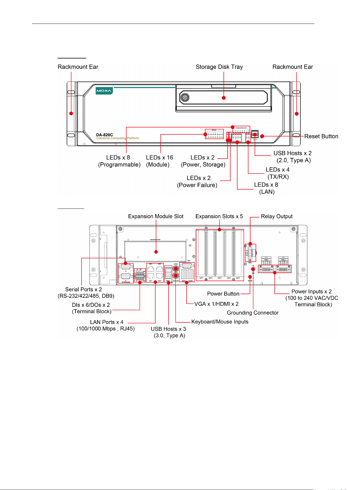
Appearance
Front View
Rear View
Page 9
DA-820C Series Introduction
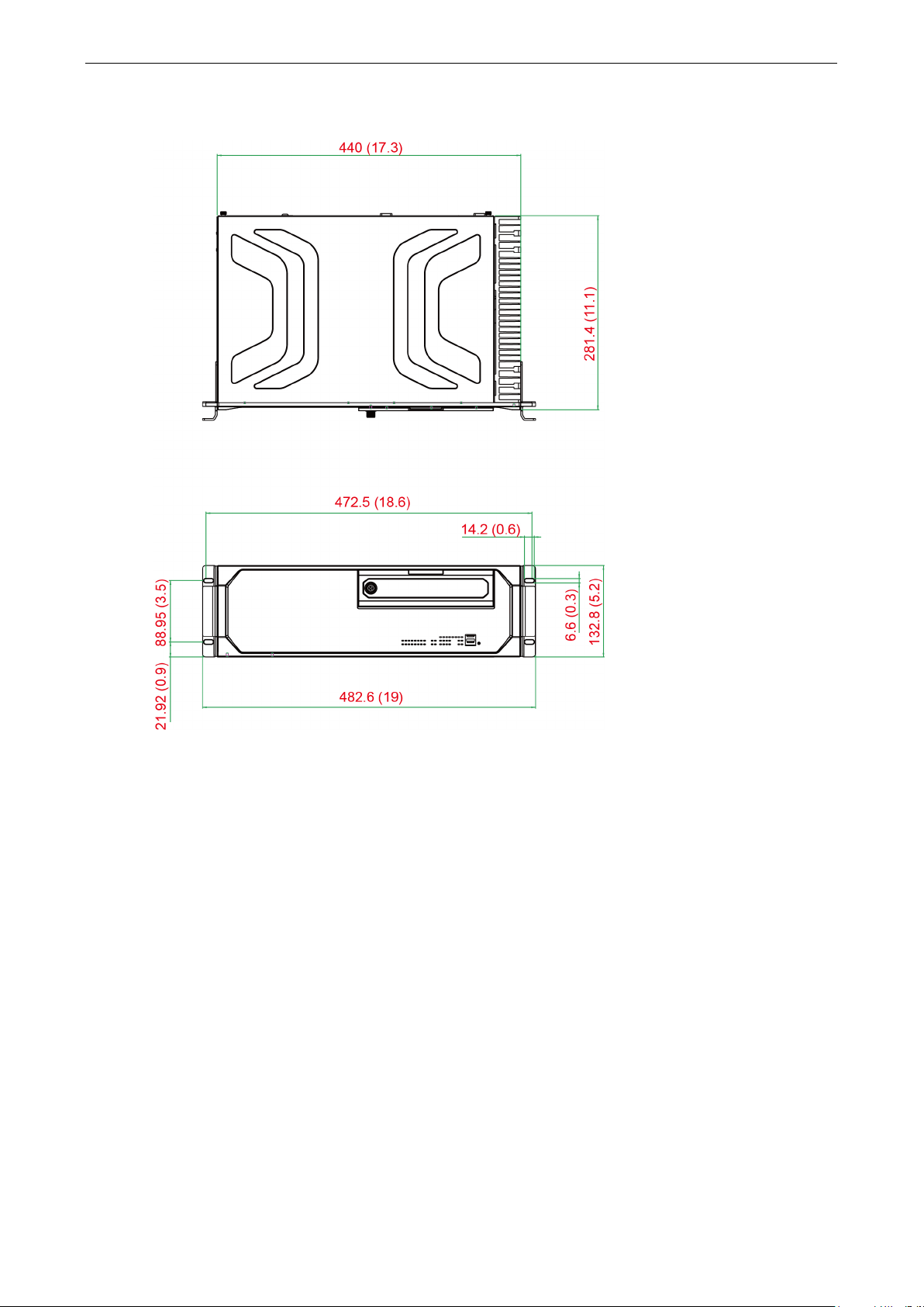
Dimensions
Features
The DA-820C computer has the following features:
• 7th Gen Intel® Core™ CPU (Kaby Lake)
• 2 built-in DDR4 memory socket, up to total 32GB capacity
• 2 x USB 2.0 and 3 x USB 3.0 type A ports for high-speed peripherals
• 1 PCIe x16, 1 PCIe x4, 2 PCIe x1 slots and 1 PCI slots for expansion modules
• 4 x hot swappable 2.5” HDD/SSD slots, supported by Intel® RST RAID 0/1/5/10
• Highly reliable design, supporting dual power and PRP/ HSR technology (with PRP/HSR expansion module)
• IEC 61850-3, IEEE 1613, and IEC 60255 compliant for power substation automation systems
• EN 50121-4 compliant for railway wayside applications
• 2 x HDMI (v1.4) + 1x VGA
• 6 x DI/ 2 x DO and alarm relay
Unit = mm (inch)
Page 10

DA-820C Series Introduction
NOTE
The latest specifications for Moxa’s products can be found at
Hardware Block Diagram
DA-820C Basic System
Hardware Specifications
https://moxa.com.
Page 11

2
2. Hardware Installation
The DA-820C embedded computers are compact and rugged, making them suitable for industrial applications.
The LED indicators allow users to monitor performance and identify trouble spots quickly, and multiple ports
are provided for connecting a variety of different devices. The DA-820C embedded computers come with a
reliable and stable hardware platform that lets you devote the bulk of your time to application development.
This chapter describes hardware installation and connector interfaces of the DA-820C embedded computers.
The following topics are covered in this chapter:
Installing Rackmount Ears
Wiring Requirements
Connecting the Power
Wiring the Power Inputs
Grounding the Chassis
Power Wiring Methods
Reset Button
LED
Connecting to Displays
Connecting USB Devices
Installing a USB Dongle Kit
Serial Ports
Gigabit LAN Ports
Digital Inputs/Digital Outputs
Relay Output
Upgrading the Memory Module
Installing an mSATA Storage Card
Installing SATA Hard Disks
Installing the Expansion Module
Inserting the PCIe/PCI Modules
Page 12
DA-820C Series Hardware Installation
2-2
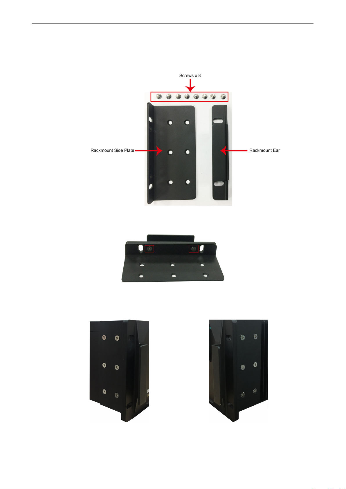
Installing Rackmount Ears
The DA-820C computer comes with two Rackmount Ear Kits that allow users to install the computer on a rack.
The Rackmount Ear Kit includes the following items.
Follow these steps for the installation.
1. Attack the rackmount ear to the side plate, and fasten two screws tightly.
2. Attach the side plate on one side of the
DA-820C computer, and fasten six screws
tightly.
3. Use the same method to install another
Rackmount Ear Kit and attach to the other
side of the computer.
Page 13
DA-820C Series Hardware Installation
2-3
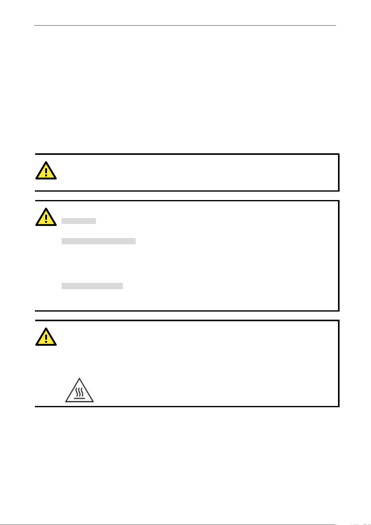
ATTENTION
Do not run signal or communication wiring and power wiring in the same wire conduit. To avoid interference,
wires with different signal characteristics should be routed separately.
ATTENTION
Safety First!
Be sure to disconnect the power cord before installing and/or wiring
Electrical Current Caution!
Calculate the maximum possible current in each power wire and common wire. Observe all electrical codes
dictat
If the current goes above the maximum rating, the wiring could overheat, causing serious damage to your
equipment.
Temperature Caution!
Be
e internal components generate heat, and
consequently the
Restricted Access Location
This equipment is intended to be used in Restrict Access Location, like computer room. The access can only be
gained by SERVICE PERSONS or by USERS who have been instructed about the metal chassis of the equipment
is so hot that service persons have to pay special attention or take special protection before touching it.
Further, the access is through
professional person can access the restrict access location.
Wiring Requirements
The following common safety precautions should be observed before installing any electronic device:
• Power wires and communication/signal wires should be routed through separate paths. If power and
communication/signal wires must cross paths, make sure the wires are perpendicular at the intersection
point.
NOTE: Do not run signal or communication wiring and power wiring in the same wire conduit. To avoid
interference, wires with different signal characteristics should be routed separately.
• Use the type of signal transmitted through a wire to determine which wires should be bundled together and
which kept separate. The rule of thumb is that wiring that carries similar electrical signals can be bundled
together.
• When necessary, we strongly advise labeling the wiring for all devices in the system.
ing the maximum current allowable for each wire size.
careful when handling the unit. When the unit is plugged in, th
outer casing may feel hot to the touch.
your device.
the use of key or security identity system. Only authorized by well trained
External metal parts are hot!! Before touching it, special attention or protection is
necessary.
Page 14
DA-820C Series Hardware Installation
2-4
NOTE
The Power LED o
f the
P
r
jumper on the terminal block.
Connecting the Power
The DA-820C provides dual power inputs using a terminal block, which is located on the rear panel. Connect the
power cord wires to the screws, and then tighten the screws. The Power LED will light up to indicate that power
is being supplied to the DA-820C, after which the BIOS will initialize the flash disk module, causing the Storage
LED to blink. It should take about 30 to 60 seconds for the operating system to complete the boot up process.
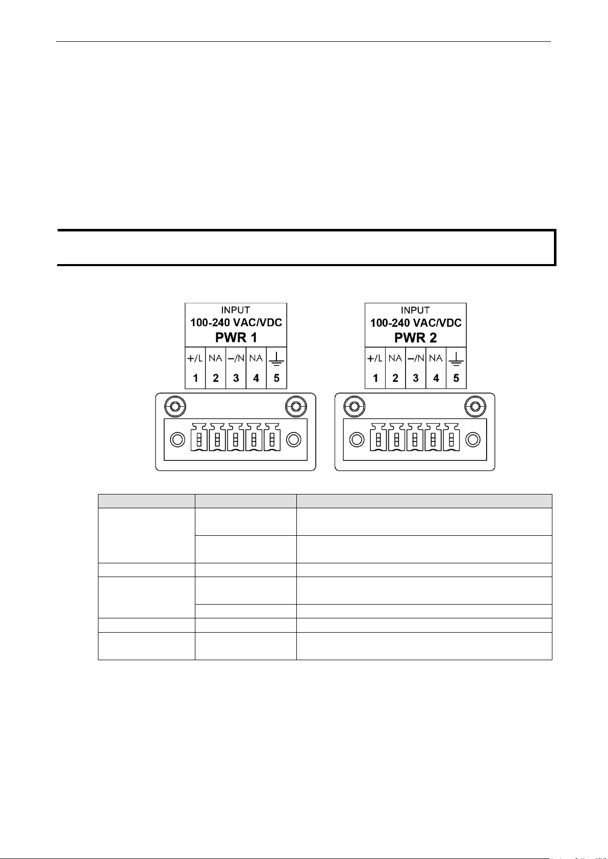
Wiring the Power Inputs
Refer to the following diagrams and table for a detailed description of the power input wiring. The terminal
numbers referred to in the table are shown in the diagrams below.
ower LED, refer the LED section in the chapter.
Terminal Number Description Note
n the front panel will turn on if the computer is losing power. For details on the behavior o
Power Line
1
Power Positive
2 NA No function
3
4 NA No function
5 Bond Earth
Power Neutral
Power Negative PWR Negative is connect to the – terminal for the DC Power
PWR Line is connected to the Line (L) terminal for the AC
power source.
PWR Positive is connect to the + terminal for the DC powe
source
PWR Neutral is connected to the Neutral (N) terminal for
the AC power source.
Bond Earth is connected to the Chassis Ground via a
Page 15
DA-820C Series Hardware Installation
2-5
ATTENTION
If protective earthing is used as a safeguard, the instructions s
protective earthing conductor to the installation protective earthing conductor (for example, by means of a
power cord connected to a socket
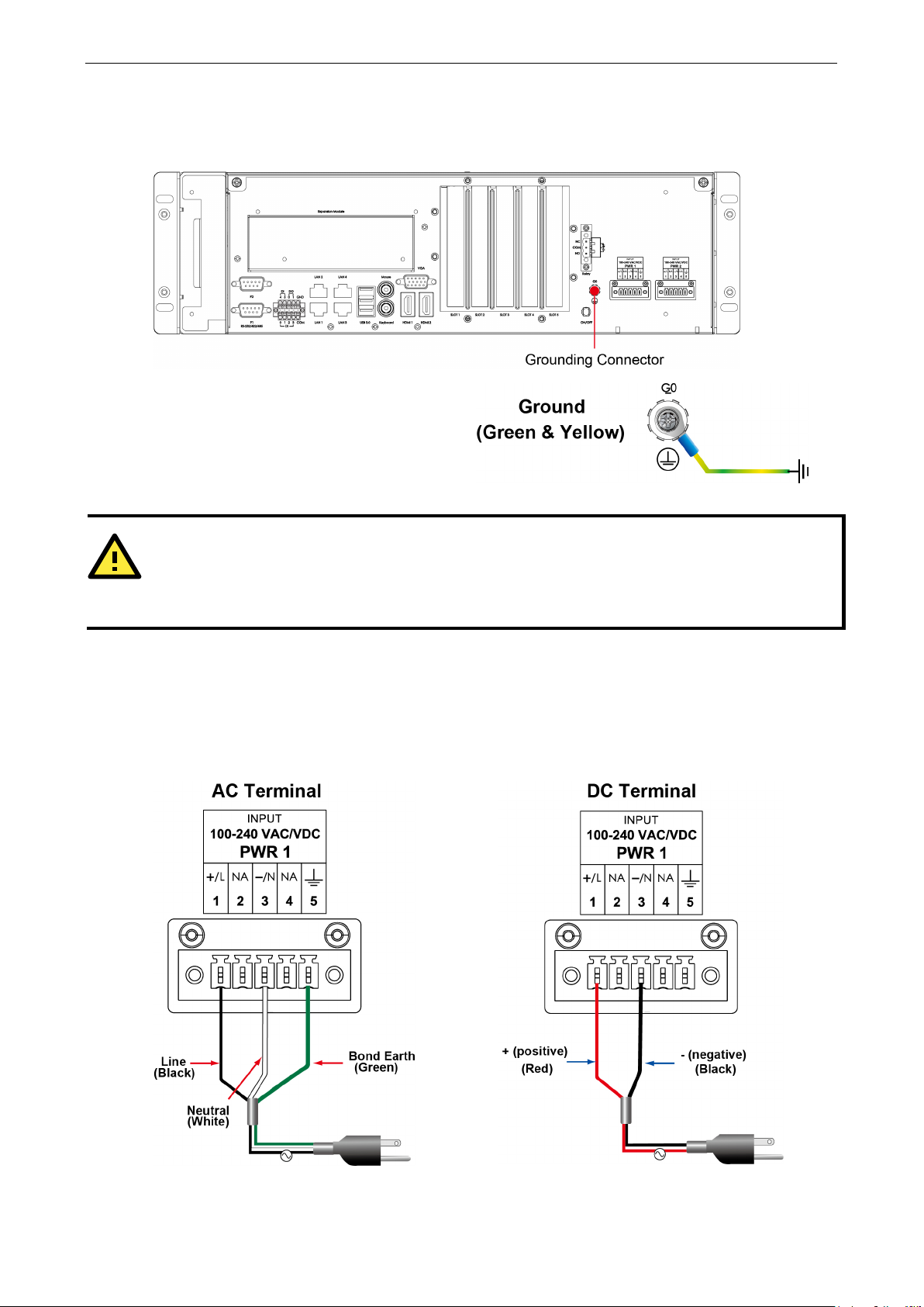
Grounding the Chassis
There is a grounding connector located on the rear panel of the computer.
Connect the connector to the chassis ground
source.
Power Wiring Methods
The DA-820C comes with single or dual power inputs; both AC and DC power sources are supported. Refer to
the following diagrams for detailed wiring methods.
hall require connection of the equipment
-outlet with earthing connection).
Page 16

DA-820C Series Hardware Installation
2-6
ATTENTION
Equipment must be installed acc
In addition, there is a power button switch on the rear panel, which allows users to push to power on the
computer again in case the computer is in the sleep or hibernate mode.
Reset Button
Pressing the Reset button initiates a hardware warm reboot. The button plays the same role as a desktop PC’s
reset button. After pressing the reset button, the system will reboot automatically. During normal use, you
should NOT use the Reset Button. You should only use this button if the software is not working properly. To
protect the integrity of data being transmitted or processed, you should always reset the system from the
operating system with the software reboot function.
ording to the applicable country’s wiring codes.
Page 17
DA-820C Series Hardware Installation
2-7
NOTE
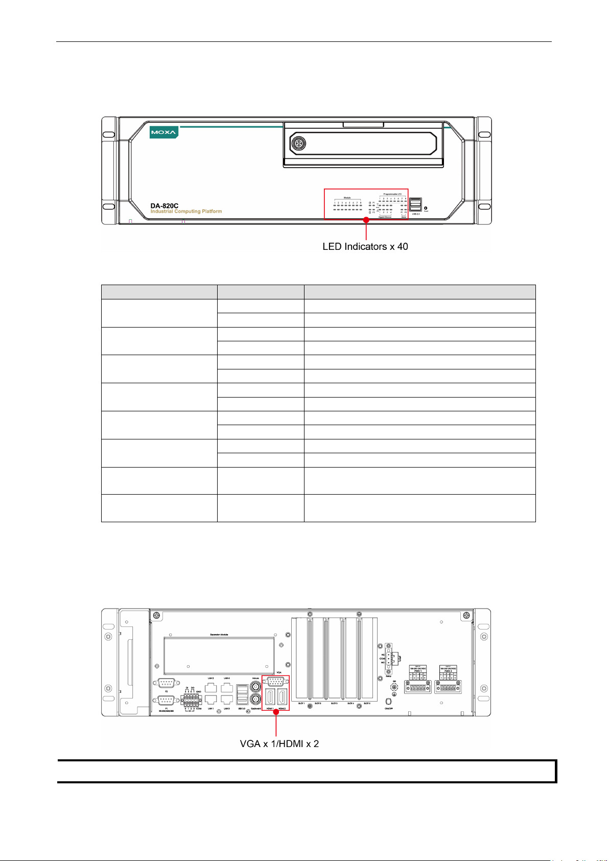
LED
There are 40 LED indicators on the front panel.
Information about each LED indicator is given in the following table.
LED Color Description
Power Green Power is on
Off No power input
Storage Yellow/Blinking Data is being written to or read from the storage unit
Off Storage unit is idle
P1 Off The 1st power supply is on
Red Error in the 1st power supply
P2 Off The 2nd power supply is on
Red Error in the 2nd power supply
Gigabit LAN LEDs 1 to 4 Green 100 Mbps Ethernet mode
Orange 1000 Mbps (Gigabit) Ethernet mode
Serial Port P1/P2 Green Tx: Serial data is being transmitted
Yellow Rx: Serial data is being received
Programmable LEDs 1 to 8 Green/
Blinking
Module LEDs 1 to 8 Green/Orange/
Blinking
Can be used to indicate statuses or for debugging, as
defined by users.
Reserved for LAN-port and serial-port expansion cards.
Connecting to Displays
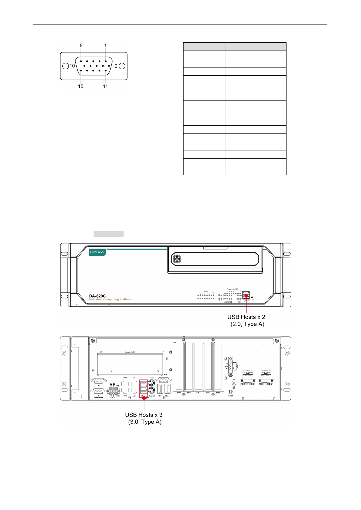
The DA-820C comes with 1 VGA interface that uses D-Sub 15-pin female connectors. In addition, 2 HDMI
interfaces are also provided on the rear panel.
In order to have a highly reliable video streaming capability, choose HDMI-certified HDMI cables.
Page 18
DA-820C Series Hardware Installation
2-8
9
VCC
For the pin definitions of the VGA connector, refer to the following figure and table.
Pin No. Signal Definition
1 RED
2 GREEN
3 BLUE
4 NC
5 GND
6 GND
7 GND
8 GND
10 GND
11 NC
12 DDC Data
13 HSYNC
14 VSYNC
15 DDC Clock
Connecting USB Devices
The DA-820C comes with 2 USB 2.0 ports on the front panel and 3 USB 3.0 ports on the rear panel. The USB
ports can be used to connect to other peripherals, such as flash drives for expanding the system’s storage
capacity. In addition, both USB ports support system boot up, which can be activated by modifying the BIOS
settings. See Chapter 3: BIOS Setup for details.
Page 19
DA-820C Series Hardware Installation
2-9
NOTE
The USB Dongle Kit is an option
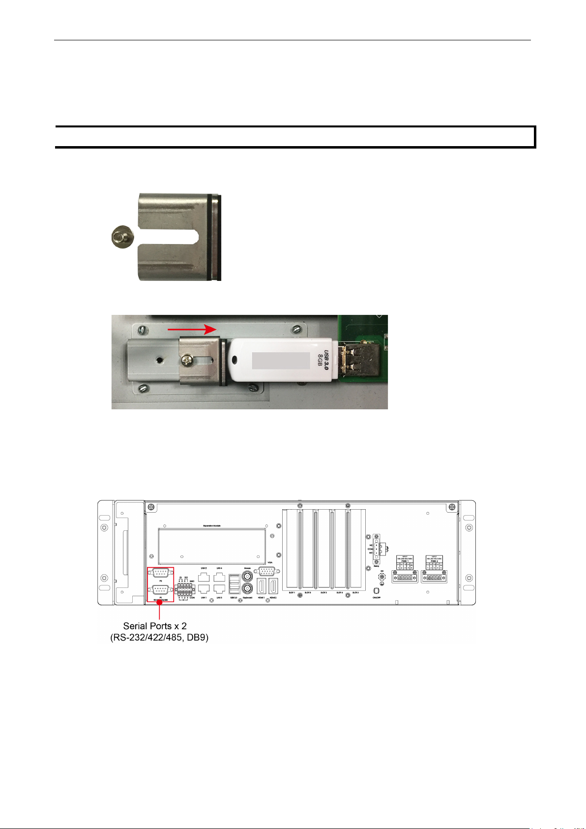
Installing a USB Dongle Kit
You can use a USB Dongle Kit to secure your USB dongle inside your DA-820C computer.
To install a USB Dongle Kit inside your DA-820C computer, do the following:
1. Power off the DA-820C computer and remove the upper cover of the computer.
2. The USB Dongle Kit includes a USB plate and a screw.
3. Attach the USB device to the USB port inside the DA-820C computer. Place the USB plate on the rail, and
push right to the USB device as close as possible. Finally, fasten the screw on the plate.
4. Place the upper cover of the computer.
al accessory that can be purchased separately.
Serial Ports
The DA-820C comes with 2 software-selectable RS-232/422/485 serial ports on the rear panel.
Page 20

DA-820C Series Hardware Installation
2-10
3
Rx+
TRD(1)+
The ports use DB9 male connectors. Refer to the following table for the pin assignments:
Pin RS-232 RS-422 RS-485
1 DCD TxDA(-) TxDA(-) –
2 RxD TxDB(+) TxDB(+) –
3 TxD RxDB(+) RxDB(+) DataB(+)
4 DTR RxDA(-) RxDA(-) DataA(-)
5 GND GND GND GND
6 DSR – – –
7 RTS – – –
8 CTS – – –
Gigabit LAN Ports
The DA-820C has 4 Gigabit LAN ports. When a LAN cable is properly connected, the LEDs on the front panel will
glow to indicate a proper connection.
(4-wire)
RS-485
(2-wire)
Refer to the following figure and table for the pin sequence and definitions.
Pin 10/100 Mbps 1000 Mbps
1 Tx+ TRD(0)+
2 Tx- TRD(0)-
4 – TRD(2)+
5 – TRD(2)-
6 Rx- TRD(1)-
7 – TRD(3)+
8 – TRD(3)-
Page 21

DA-820C Series Hardware Installation
2-11
Digital Inputs/Digital Outputs
The DA-820C comes with six digital inputs and two digital outputs in a terminal block. Refer to the following
figure for the location of the DI/DO connectors.
For pin definitions and wiring methods, see the figures below.
Relay Output
The DA-820C provides a relay output located on the rear panel of the computer.
Refer to the figure on the right for detailed pin
definition of the relay output connectors.
Page 22

DA-820C Series Hardware Installation
2-12
Upgrading the Memory Module
The DA-820C embedded computer supports 2 ECC registered DDR3 1333/1600 SODIMM modules, for up to 16
GB of memory (2 slots, each with 8 GB). To upgrade the SDRAM memory module, follow these instructions:
1. Disconnect the DA-820C from its power source.
2. Unfasten the screws on the back of the computer, and then take off the upper cover.
3. Find the location of the SDRAM memory socket.
4. If a memory module is already installed in the socket, push the two fasteners to free and then remove the
module. Insert the new memory module into the socket, making sure you insert the SDRAM in the correct
direction. Push down the memory module, making sure that the two fasteners snap in place and are holding
the module firmly.
5. When finished, replace the upper cover of the computer and fasten the screws.
Page 23

DA-820C Series Hardware Installation
2-13
Installing an mSATA Storage Card
The DA-820C embedded computer comes with an mSATA socket. To insert an mSATA storage card, follow
these instructions.
1. Disconnect the DA-820C from its power source.
2. Unfasten the screws on the back of the computer, and then take off the upper cover.
3. Find the location of the mSATA socket.
4. Insert the mSATA storage card into the socket, and fasten the two screws to fix the card.
5. When finished, restore the upper cover of the computer and fasten the screws.
Page 24

DA-820C Series Hardware Installation
2-14
ATTENTION
The DA
hot swap and PnP (Plug and Play)
functions. It is necessary to remove power source first before inserting or removing the
card.
-820C rackmount computer does not support the mSATA storage card
Installing SATA Hard Disks
The DA-820C comes with four SATA slots that allow users to install four 2.5” SATA HDD/SSD in the computer.
Follow these steps to install a SATA disk.
1. Unfasten the screw on the storage disk tray, and pull down the tray door.
2. There are four disk trays available.
mSATA storage
The installation sequence of the disks is indicated in
the diagram below. You may install your SATA disk in
any slot.
3. Each storage disk tray comes with a clutch. Pull the clutch to the right to take out the tray.
Page 25

DA-820C Series Hardware Installation
2-15
4. Place the SATA disk on the tray.
5. Turn back to the rear side of the tray, and fasten four screws. See the following diagram for details.
6. There are two plastic rails inside the slot. Make sure to insert the storage tray into the rails.
7. Push the disk tray into the computer; make sure the storage tray has been successfully inserted. Use the
same method to install other three disks if necessary.
8. Restore the storage tray door to complete.
Page 26

DA-820C Series Hardware Installation
2-16
ATTENTION
Please ensure to power off the computer first and then install/remove the expansion modules.
Installing the Expansion Module
The DA-820C comes with an expansion socket, allowing users to install various expansion modules such as
Gigabit Ethernet module and serial communication module. Follow these steps.
1. Unfasten the two screws on the module plate, and then remove the plate.
2. Insert the expansion module into the slot.
3. Make sure the module has been successfully inserted. Fasten the screws to complete.
Page 27

DA-820C Series Hardware Installation
2-17
Gen. 3
Gen. 3
Gen. 2
Gen. 2
Inserting the PCIe/PCI Modules
The DA-820C computer comes with five slots supporting PCIe/PCI interfaces; users can install the modules for
various industrial communications. Follow these steps.
1. Unfasten the screws on the rear panel and remove the upper cover.
2. Find the location of these slots.
Refer to the following table for the interface details of each slot (from left to right)
Slot 1 Slot 2 Slot 3 Slot 4 Slot 5
PCIe x16
PCIe x4
PCIe x1
PCIe x1
PCI
Page 28

DA-820C Series Hardware Installation
2-18
3. To insert the module, remove the screw on the protection plate first, and then remove the plate.
4. Insert the module on the slot carefully. Make sure the module has been successfully inserted.
5. Fasten the screw on the module.
6. Restore the upper cover and fasten the screws to complete.
Page 29

DA-820C Series Hardware Installation
2-19
ATTENTION
Please ensure to powe
r off the computer first and then install/remove the PCIe/PCI modules.
Page 30

3
3. BIOS Setup
This chapter describes the BIOS settings of the DA-820C computer. The BIOS is a set of input/output control
routines for peripherals, and is used to initialize system peripherals before the operating system is loaded. The
BIOS setup allows the user to modify the system configurations of these peripherals’ basic input/output.
The following topics are covered in this chapter:
Entering the BIOS Setup
Main Page
Advanced Settings
Boot Configuration
SATA Configuration
Intel Rapid Storage Technology
CPU Configuration
Active Management Technology Support
Video Configuration
Chipset Configuration
SIO ITE8786E
Console Redirection
Security Settings
Current TPM Device
TPM State
Clear TPM
Set Supervisor Password
Power Settings
Wake on LAN
Auto Wake on S5
Power On USB3 (Rear)
Power On USB2 (Front)
Power On USB2 (Internal)
PS/2 Keyboard Power-Up
Boot Settings
Boot Type
Network Stack
PXE Boot capability
Timeout
EFI
Exit Settings
Exit Saving Changes
Save Change Without Exit
Exit Discarding Changes
Load Optimal Defaults
Load Custom Defaults
Save Custom Defaults
Discard Changes
Enable AMT
Use AMT
Upgrading the BIOS
Page 31

DA-820C Series BIOS Setup
3-2
F1
F5/ F6
F9
F10
General Help
Change Values
Setup Defaults
Save and Exi
↑↓
←→
ESC
EN TER
Select Item
Select Menu
Exit
Select or go to Submenu.
Entering the BIOS Setup
To enter the BIOS setup utility, press the “F2” key while the system is booting up. The main BIOS Setup
screen will appear. Five options will be available:
• Continue: Continue to boot up
• Boot Manager: Select the device for booting up
• Device Manager:
• Boot From File: Select the UEFI boot up file
• Setup Utility: Enter the BIOS configuration menu
• Intel® Management Engine BIOS Extension: Enter the AMT configuration menu
Select F2 to enter the BIOS configuration.
Enter the device configuration menu
When you enter Setup Utility, a basic description of each function key is listed at the bottom of the screen.
Refer to these descriptions to learn how to use them.
t
.
Page 32

DA-820C Series BIOS Setup
3-3
The BIOS configuration screen will be shown when you enter the Setup Utility option, as shown in the
following figure.
Note that the Processor Type information for will vary depending on which model you purchased.
Page 33

DA-820C Series BIOS Setup
3-4
Main Page
The Main page displays basic system hardware information, such as model name, BIOS version, and CPU type.
Page 34

DA-820C Series BIOS Setup
3-5
NOTE
The Active Management Technology is not supported in
Advanced Settings
Select the “Advanced” option in the main menu to open the “Advanced Features” screen.
the KL3 models.
Page 35

DA-820C Series BIOS Setup
3-6
Boot Configuration
This item allows users to configure the default value of Numlock.
Options: On (default), Off.
SATA Configuration
The host drive controller can be configured for AHCI (default) or Intel RST Premium mode.
Page 36

DA-820C Series BIOS Setup
3-7
Serial ATA Port
This setting allows the user to display information about the installed drives.
SATA Port—HotPlug
This item allows you to enable/disable hot-plugging capabilities (the ability to remove the drive while the
computer is running) for installed storage drives.
Options: Disabled (default), Enabled
RAID
Set HDC configuration as “Intel RST Premium” to enable redundant array of inexpensive disks technology. The
DA-820 supports RAID levels 0, 1, 5, 10, and Recovery.
Recovery utilizes RAID 1 (mirroring) functionality to copy data from a designated master drive to a designated
recovery drive. The master drive data can be copied to the recovery drive either continuously or on request.
When using the continuous update policy, changes made to the data on the master drive while the system is
not docked are automatically copied to the recovery drive when the system is re-docked. When using the on
request update policy, the master drive data can be restored to a previous state by copying the data on the
recovery drive back to the master drive.
These figures were obtained from Wikipedia. Please refer to
http://en.wikipedia.org/wiki/Standard_RAID_levels for details.
Page 37

DA-820C Series BIOS Setup
3-8
From Device Management to configure the following Intel Rapid Storage Technology.
Intel Rapid Storage Technology
This section allows users to configure Intel® Rapid Storage Technology.
Page 38

DA-820C Series BIOS Setup
3-9
NOTE
Hyper
CPU Configuration
-Threading is not supported in the KL5 models.
Page 39

DA-820C Series BIOS Setup
3-10
Active Processor Cores
This item indicates the number of cores to enable in each processor package.
Hyper-Threading
This feature makes the processor resources work more efficiently, enabling multiple threads to run on each
core. It also increases processor throughput, improving overall performance on threaded software.
Options: Disabled, Enabled (default)
Active Management Technology Support
This item allows you to configure the Intel® Active Management Technology (KL3 model does not support this
function).
AMT BIOS Features
This item allows users to enable/disable Intel® Active Management Technology BIOS Extension.
Note: iAMT H/W is enabled by default. This option just controls the BIOS extension execution.
Options: Disabled, Enabled (default)
ME Unconfig on RTC Clear State
Disabling this option will cause ME not to unconfigure on RTC clear.
Options: Disabled, Enabled (default)
Unconfigure ME
Unconfigure ME with resetting MEBx password to default.
Page 40

DA-820C Series BIOS Setup
3-11
Video Configuration
This item allows you to configure the built-in Internal Graphics Device or external PCI Express Graphics card.
Options: IGFX (default), PEG
Page 41

DA-820C Series BIOS Setup
3-12
Internal Graphics Device
This option allows you to enable/disable the internal graphics device.
Options: Enabled (default), Disabled
IGD—DVMT Pre-Allocated
This item allows you to configure pre-allocated memory capacity for the IGD. Pre-allocated graphics memory
is invisible to the operating system.
Options: 12 M, 16M, 20M, 24M, 28M, 32M (default), 36M, 40M, 44M, 48M, 52M, 56M, 60M, 64M
DVMT is a BIOS solution where “the optimum amount of memory is dynamically allocated and de-allocated as
needed for balanced graphics and system performance, through Intel® Direct AGP and a highly efficient
memory utilization scheme.” DVMT ensures the most efficient use of available system memory resources for
maximum 2D/3D graphics performance.
IGD—DVMT Size
This item allows you to configure the maximum amount of memory DVMT will use when allocating additional
memory for the internal graphics device.
Options: 256 MB (default), 128 MB, Max.
Page 42

DA-820C Series BIOS Setup
3-13
PCI Express Graphic
This option allows you to configure the external PCI Express Graphics card.
PCIEx16-GEN X
Set the PCIEx16 interface speed. The default is auto-detect. You can set a fixed speed for when a card cannot
be detected.
Options: Auto (default), Gen1, Gen2, Gen3
Always Enable PEG
When the system doesn't detect a PCIEx16 card, it will disable the PCIE x16 interface to free up resources.
Enabling this setting will ensure that the interface is always enabled.
Options: Disabled, Enabled, Auto (default)
Page 43

DA-820C Series BIOS Setup
3-14
Chipset Configuration
This item allows you to configure the chipset settings.
Power ON after Power Failure
This item allows you to enable/disable the computer from automatically powering up after a system crash.
Options: ON (default), OFF, Last State
DO-0 Level
This item allows users to set the DO 0 as high or low.
Options: High (default), Low
DO-1 Level
This item allows users to set the DO 1 as high or low.
Options: High (default), Low
Page 44

DA-820C Series BIOS Setup
3-15
SIO ITE8786E
This section allows users to configure serial port settings.
Serial Port A
This function allows users to configure the resources for serial port A.
Disable: No resources
Enable: User configures the resources
Auto (default): EFI/OS chooses the resources
Serial Port B
This function allows users to configure the resources for serial port B.
Disable: No resources
Enable: User configures the resources
Auto (default): EFI/OS chooses the resources
Page 45

DA-820C Series BIOS Setup
3-16
Hardware Monitor
This item allows you to view stats such as CPU and system temperature, voltage levels, and other chipset
information.
The voltage values will vary depending on which model you purchased. There is a 5% tolerance for temperature
values. Note that at 100°C the accuracy of CPU temperature readings are in the range of -5°C to +10°C. This
deteriorates to -10°C to +15°C at 50°C. The CPU temperature readings are saturated at some point below
50°C. Any CPU reading below 50°C is unreliable, and may only be interpreted as indicating a temperature
below 50°C. For system temperature, there is a 5% tolerance for the temperature values.
Console Redirection
When the Console Redirection Function is enabled, the console information will be output to both the HDMI
monitor and through the serial port.
Options: Disabled (default), Enabled
Page 46

DA-820C Series BIOS Setup
3-17
Security Settings
This section allows users to configure security-related settings with a supervisor password and user password.
Current TPM Device
This item shows if the system has TMP device and its type.
TPM State
This item allows you view the status of current TPM settings.
Clear TPM
This item allows users to remove all TPM context associated with a specific owner.
Options: Disabled (default), Enabled
Page 47

DA-820C Series BIOS Setup
3-18
Set Supervisor Password
This item allows you to set the supervisor password. Select the Set Supervisor Password option and enter
the password and confirm the password again.
To delete the password, select the Set Supervisor Password option and enter the old password; leave the
new password fields blank, and then press enter.
After setting the supervisor password, users can choose when asking input password screen will pop up.
Page 48

DA-820C Series BIOS Setup
3-19
Enable: System will ask input password on post time.
Disable: System will ask for the password to go to the setup utility.
Config-Only: System will only ask for the password when you select the config (F2) option
Power Settings
The section allows users to configure power settings.
Wake on LAN
This feature is used to wake the system by a LAN device from a remote host.
Options: Enabled (default), Disabled
Auto Wake on S5
This item allows you to configure the computer to wake from S5 status. S5 stands for Soft Off, where the PSU
remains engaged but power to all other parts of the system is cut. Auto-wake on S5 schedules a soft-reboot at
certain periodic times that may be specified in the BIOS.
Options: Disabled (default); By Every Day (user specifies a regular daily time when the computer will power
up); By Day of Month (user specifies a regular day each month when the computer will power up)
Power On USB3 (Rear)
This item allows users to power on or power off the USB ports on the rear panel.
Options: Disabled, Enabled (default)
Page 49

DA-820C Series BIOS Setup
3-20
NOTE
If you do not add any stor
Power On USB2 (Front)
This item allows users to power on or power off the USB ports on the front panel.
Options: Disabled, Enabled (default)
Power On USB2 (Internal)
This item allows user to powers on or power off the internal USB port inside the computer.
Options: Disabled, Enabled (default)
PS/2 Keyboard Power-Up
This item allows users to press CTRL+P to wake up the system that PSU remains engaged but power to all other
parts of the system is cut
Options: Disabled (default), Enabled
Boot Settings
The section allows users to configure boot settings.
age, you will not see the EFI option.
Page 50

DA-820C Series BIOS Setup
3-21
Boot Type
This item allows you to enable/disable the quick boot function.
Options: Dual Boot Type, Legacy Boot Type, UEFI Boot Type (default)
Network Stack
It deploys an Internet Protocol (IP) stack. The IP stack provides an application library to open/close
connections to remote devices and send/receive data between the remote devices.
Options: Disabled (default), Enabled
PXE Boot capability
PXE Booting is booting a system over a network. This item allows users to start PXE over IPv4 or IPv6
Options: Disabled (default), UEFI: IPv4, UEFI: IPv6, UEFI: IPv4/IPv6
Timeout
This item allows users to set the number of second that the firmware will wait before booting the original default
boot selection.
EFI
This item allows users to select the boot order. Use F5 (move up) or F6 (move down) to change the value.
Exit Settings
The section allows users to exit the BIOS environment.
Page 51

DA-820C Series BIOS Setup
3-22
Exit Saving Changes
This item allows you to exit the BIOS environment and save the values you have just configured.
Options: Yes (default), No
Save Change Without Exit
This item allows you to save changes without exiting the BIOS environment.
Options: Yes (default), No
Exit Discarding Changes
This item allows you to exit without saving any changes that might have been made to the BIOS.
Options: Yes (default), No
Load Optimal Defaults
This item allows you to revert to the factory default BIOS values.
Options: Yes (default), No
Load Custom Defaults
This item allows you to load custom default values for the BIOS settings.
Options: Yes (default), No
Page 52

DA-820C Series BIOS Setup
3-23
NOTE
The
Save Custom Defaults
This item allows you to save the current BIOS values as a “custom default” that may be reverted to at any time
by the “load custom defaults” selection just above.
Options: Yes (default), No
Discard Changes
This item allows you to discard all settings you have just configured.
Options: Yes (default), No
Enable AMT
AMT function is not supported for KL3 models.
To enter the BIOS setup utility, press the “F2” key while the system is booting up. The main BIOS Setup
screen will appear. Five options will be available:
1. Select Intel® Management Engine BIOS Extension to enter the AMT configuration.
Page 53

DA-820C Series BIOS Setup
3-24
2. Press <Enter> to start the login procedure.
3. Type the default password: admin
Page 54

DA-820C Series BIOS Setup
3-25
4. Type the new password. It must include both upper-case and lower-case characters, numbers, and special
symbols. E.g., Admin’12.
5. Select Intel® AMT Configuration to enable remote access without a local user present for consent, select
User Consent, and then select User Opt-in and change the value to None.
6. Set static IP or DHCP by request.
Page 55

DA-820C Series BIOS Setup
3-26
7. Set Activate Network Access to enable remote access capability.
Use AMT
You can use any of the available AMT tools to execute the remote management function. The easiest method
is using a web browser.
1. Type the IP for your DA-820C that was configured in the AMT configuration with port 16992. The AMT logon
screen will appear.
Page 56

DA-820C Series BIOS Setup
3-27
NOTE
The
NOTE
Refer to the Intel AMT Implementation and Reference Guide for details:
ht
default.htm?turl=WordDocuments%2Faccessingintelamtviathewebuiinterface.htm
2. Click on “Log On” and type the username (admin) and password to log in and control the DA-820C
remotely.
DA-820C’s AMT port is LAN1.
tps://software.intel.com/sites/manageability/AMT_Implementation_and_Reference_Guide/
Page 57

DA-820C Series BIOS Setup
3-28
Upgrading the BIOS
This section describes how to upgrade the BIOS. However, note that it is easy to permanently damage the
computer when upgrading the BIOS. We strongly recommend that you contact Moxa’s technical support staff
for assistance in order to obtain all the necessary tools and the most current advice before attempting to
upgrade the BIOS on any Moxa device.
Step 1: Create a Bootable USB Disk
Before upgrading the BIOS, every user should first create a bootable USB RAM drive as a system rescue device.
1. Search “format”, then select Create and format hard disk partitions.
Page 58

DA-820C Series BIOS Setup
3-29
2. Right click on the USB disk then select “Format”.
3. Select “FAT32”, and click OK to start formatting.
4. After formatting the USB disk, download the “Shell.efi”.
5. Link to “https://github.com/tianocore/edk2/branches
6. As below path, download the “Shell.efi” then rename to “bootX64.efi”.
”, select the latest branch.
Page 59

DA-820C Series BIOS Setup
3-30
7. Copy the “bootX64.efi” to USB disk \efi\boot\bootX64.efi (Note: The folder should be created by absolute
path as below).
Step 2: Prepare the Upgrade File
You must use the BIOS upgrade installation file to upgrade the BIOS. Contact Moxa’s technical department for
assistance.
1. Get the BIOS upgrade file. The file extension should be xxxx.efi
2. Copy the file to the Bootable USB Disk.
Step 3: Run the upgrade program on the Computer
1. Reboot the computer, and press F2 while booting up to go to the Boot Manager.
2. Select the USB Disk
Page 60

DA-820C Series BIOS Setup
3-31
3. Screen will be going into the SHELL environment, type fs0: then, go to the directory where the upgrade file
is located, type :xxxxxx.efi (the name is based on the upgrade file you get from Moxa).
4. The upgrade program will run automatically. Wait patiently until the procedure is finished.
5. When the upgrade is finished, the computer will automatically reboot. You may check BIOS version on the
Main page
6. If the system have more than one boot device, you will see more than one fsx (x means number)
Page 61

DA-820C Series BIOS Setup
3-32
ATTENTION
Do NOT switch off the power supply during the BIOS upgrade, since doing so may cause the system to crash.
7. Go each fsx (x means number), then type ls to view the content of the boot device. If find the upgrade file,
execute it
Page 62

A. Safety Installation Instructions
ATTENTION
There is a risk of explosion if the wrong type of battery is used. To avoid this potential danger, always
be sure to use the correct type of battery. Contact the Moxa RMA service team if you need to replace
your battery.
Caution
There is a risk of explosion if the battery is replaced by an incorrect type. Dispose of used batteries
according to the instructions on the battery.
A. RTC Battery Warning
B. Fuse Warning
A
CAUTION: For continued protection against fire, replace only with the same type and rating of fuse.
C. Rackmount Warning
The following or similar rackmount instructions are included with the installation instructions:
(1) Elevated Operating Ambient: If installed in a closed or multi-unit rack assembly, the operating ambient
temperature of the rack environment may be greater than the room ambient temperature. Therefore,
consideration should be given to installing the equipment in an environment compatible with the maximum
ambient temperature (Tma) specified by the manufacturer.
(2) Reduced Air Flow: Installation of the equipment in a rack should be such that the amount of air flow
required for safe operation of the equipment is not compromised.
(3) Mechanical Loading: Mounting of the equipment in the rack should be such that a hazardous condition is
not achieved due to uneven mechanical loading.
(4) Circuit Overloading: Consideration should be given to the connection of the equipment to the supply
circuit and the effect that overloading of the circuits might have on overcurrent protection and supply wiring.
Appropriate consideration of equipment nameplate ratings should be used when addressing this concern.
(5) Reliable Grounding: Reliable grounding of rack-mounted equipment should be maintained. Particular
attention should be given to supply connections other than direct connections to the branch circuit (e.g., by
using power strips).
 Loading...