

Page 1

P/N: 1802008200011
*1802008200011*
DA-820 Series
Quick Installation Guide
x86 Rackmount Embedded Computers
Edition 2.0, January 2018
Technical Support Contact Information
www.moxa.com/support
Moxa Americas:
Toll
-free: 1-888-669-2872
Tel:
1-714-528-6777
Fax:
1-714-528-6778
Moxa China (Shanghai office):
Toll
-free: 800-820-5036
Tel:
+86-21-5258-9955
Fax:
+86-21-5258-5505
Moxa Europe:
Tel:
+49-89-3 70 03 99-0
Fax:
+49-89-3 70 03 99-99
Moxa Asia-Pacific:
Tel:
+886-2-8919-1230
Fax:
+886-2-8919-1231
Moxa India:
Tel:
+91-80-4172-9088
Fax:
+91-80-4132-1045
2018 Moxa Inc. All rights reserved.
Page 2
- 2 -
Overview
The DA-820’s main operating system is based on the Intel® Core™
i3/i7/Celeron CPU and QM77 chipset, and supports x86 platforms. The
DA-820 has 2 VGA connections, 6 USB ports, 4 Gigabit LAN ports, and 2
RS/232/422/485 3-in-1 serial ports, and is equipped with a 4 SATA disk
interface and default support for RAID 0/1/5/10. In addition, the DA-820
is specifically designed for substation applications that require precise
time synchronization and products meeting the IEC 61850-3 standard.
The flexible design makes the DA-820 suitable for local SCADA,
environmental monitoring, video surveillance, protocol conversion, and
PRP/HSR redundancy applications, and the cybersecurity functionality
allows you to maintain secure network communications.
Package Checklist
Each basic system model is shipped with following standard items:
• DA-820 rackmount computer
• Rackmount kit
• Quick Installation Guide
• Documentation and software CD
• Warranty card
Hardware Installation
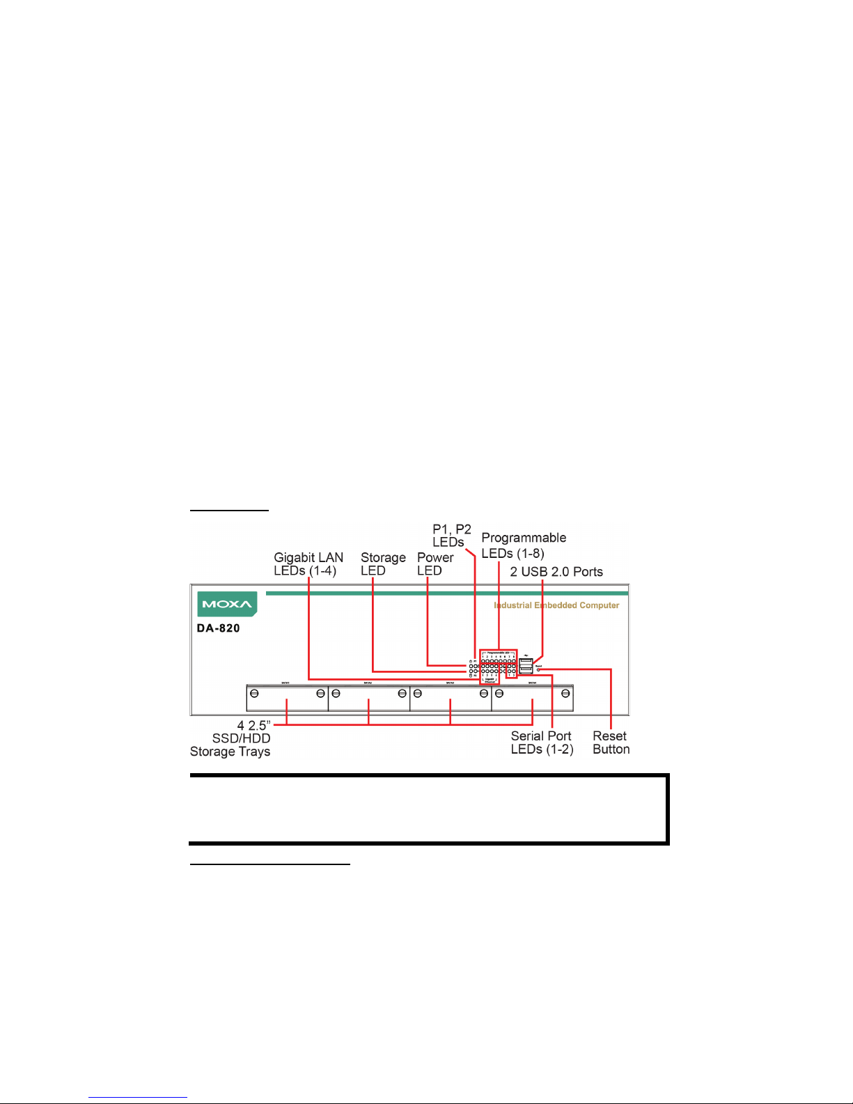
Front View
NOTE
The power input supports two types of power supply:
HV: 100 to 240 VAC/VDC
LV: 24 to 110 VDC.
Connecting the Power
Use a screwdriver to loosen the terminal connector’s clamp screws.
Connect the power cord wires to the screws, and then retighten the
screws. The Power LED will light up to indicate that power is being
supplied to the DA-820, after which the BIOS will initialize the flash disk
module, causing the Storage LED to blink. It should take about 30 to 60
seconds for the operating system to complete the boot process.
Page 3
- 3 -
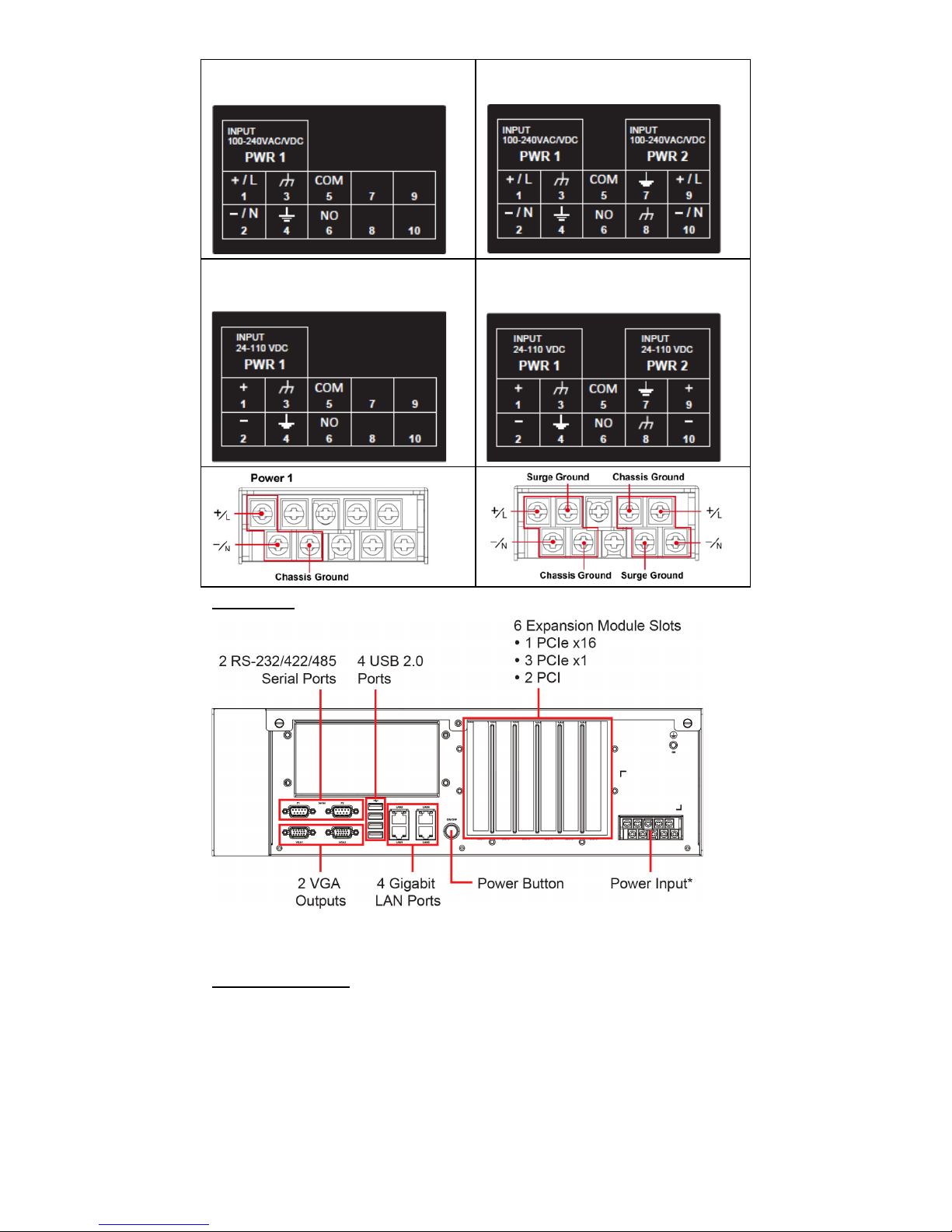
Alternating Current (AC),
Single Power
Alternating Current (AC),
Dual Power
Direct Current (DC),
Single Power
Direct Current (DC),
Dual Power
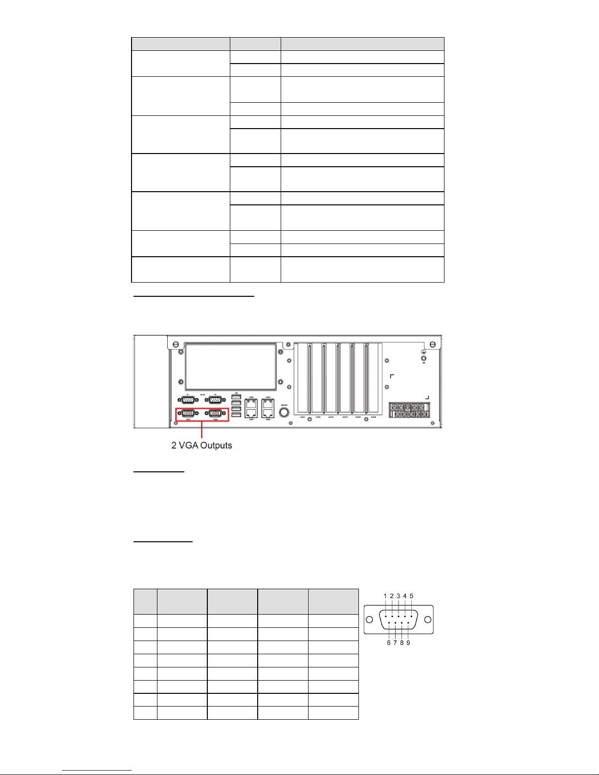
Rear View
For detailed power connection and surge protection information, refer to
the DA-820 Hardware User’s Manual.
Front Panel LEDs
There are 28 LED indicators on the front panel. The LEDs are described in
the following table:
Page 4
- 4 -
LED
Color
Description
Power
Green
Power is on
Off
No power input
Storage
Yellow/
Blinking
Data is being written to or read
from the storage unit
Off
Storage unit is idle
P1
(Non-functional for
single power supply)
Off
The 1st power supply is on
Red
Error in the 2nd power supply
P2
(Non-functional for
single power supply)
Off
The 2nd power supply is on
Red Error in the 1st power supply
Gigabit LAN LEDs
1-4
Green
100 Mbps Ethernet mode
Orange
1000 Mbps (Gigabit) Ethernet
mode
Serial Port 1/2
Green
Tx
Yellow
Rx
Programmable 1-8
Green/
Blinking
The programs 1-8 that are in
process
Connecting to a Display
The DA-820 comes with 2 VGA interfaces that use D-Sub 15-pin female
connectors.
USB Ports
The DA-820 comes with 6 USB 2.0 ports, with 4 on the rear panel and 2
on the front panel. The USB ports can be used to connect a keyboard,
mouse, or other peripherals, such as flash drives for expanding the
system’s storage capacity.
Serial Ports
The DA-820 comes with 2 software-selectable RS-232/422/485 serial
ports on the rear panel. The ports use DB9 male connectors. Refer to the
following table for pin assignments:
Pin
RS-232
RS-422
RS-485
(4-wire)
RS-485
(2-wire)
1
DCD
TxDA(-)
TxDA(-)
– 2 RxD
TxDB(+)
TxDB(+)
– 3 TxD
RxDB(+)
RxDB(+)
DataB(+)
4
DTR
RxDA(-)
RxDA(-)
DataA(-)
5
GND
GND
GND
GND
6
DSR
– – – 7 RTS
– – – 8 CTS
– – –
Page 5

- 5 -
Ethernet Ports
The DA-820 has 4 100/1000 Mbps RJ45 Ethernet ports. Refer to the
following table for pin assignments:
Pin
100 Mbps
1000 Mbps
1
Tx+
TRD(0)+
2
Tx-
TRD(0)-
3
Rx+
TRD(1)+
4 – TRD(2)+
5 – TRD(2)-
6
Rx-
TRD(1)-
7 – TRD(3)+
8 – TRD(3)-
The default IP addresses and netmasks of the Ethernet ports are shown
below. Note that the W7E models default to DHCP.
Default IP Address
Netmask
LAN 1
192.168.3.127
255.255.255.0
LAN 2
192.168.4.127
255.255.255.0
LAN 3
192.168.5.127
255.255.255.0
LAN 4
192.168.6.127
255.255.255.0
Installing Removable Storage
The DA-820 has 4 hot-swappable 2.5” SSD/HDD storage trays located on
the front panel for installing additional storage drives. Remove the screws
on the trays to install the SSD/HDD storage drives. RAID 0, 1, 5, and 10
are supported.
Configuring the Ethernet Interface
Linux Users:
To configure the network settings on your DA-820 for the first time, use
the following commands to edit the interfaces file. First, make sure all
network interfaces are offline before you reconfigure the LAN settings.
MOXA:~# ifdown –a
Next, edit the network interfaces file. The default editor on the DA-820 is
vi; however, you may use a text editor of your choice.
MOXA:~#vi /etc/network/interfaces
You may set the DA-820 for either dynamic IP addressing or static IP
addressing. For dynamic IP addressing, enter the following lines into the
network interfaces file:
# The primary network interface
auto eth0
iface eth0 inet dhcp
To configure an interface for static IP addressing, use the following
configuration. Each interface must be configured with separate entries in
the network/interfaces file; LAN1 corresponds to eth0, LAN 2 corresponds
to eth1, and so on for the remaining interfaces.
Page 6
- 6 -
# The loopback network interface
auto lo
iface lo inet loopback
# The first LAN interface, LAN 1
auto eth0
iface eth0 inet static
address 192.168.3.127
netmask 255.255.255.0
broadcast 192.168.3.255
# The second LAN interface, LAN 2
auto eth1
iface eth1 inet static
address 192.168.4.127
netmask 255.255.255.0
broadcast 192.168.4.255
Exit the vi editor by typing:
:wq
After the interfaces file has been configured, use the following commands
to reinitialize the network interfaces and activate the new settings
immediately:
Moxa:~#sync; ifup –a
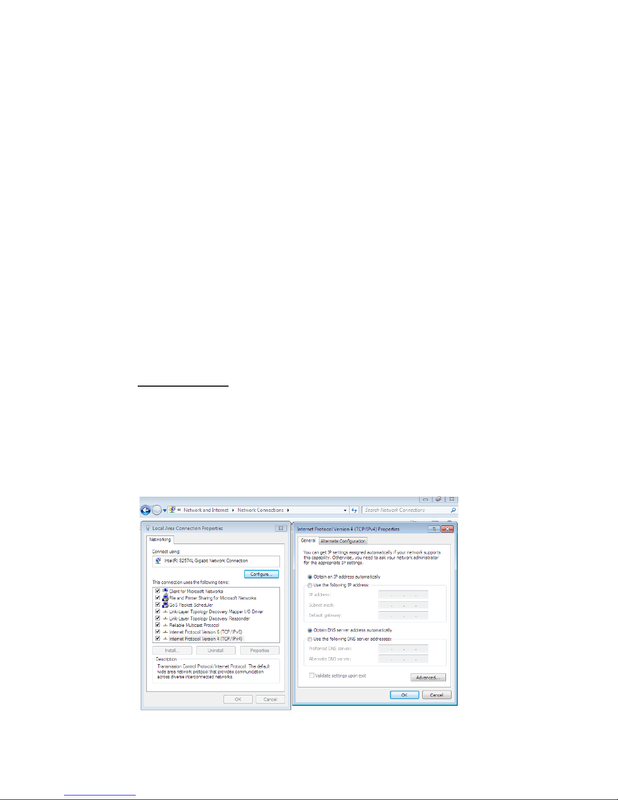
Windows 7 Users
Step 1:
Go to Start Control Panel Network and Internet
Network Connections.
Step 2:
On the Local Area Connection Properties screen, click
Internet Protocol (TCP/IP)
and select Properties.
Step 3:
Click OK after inputting the preferred IP address and
netmask.
 Loading...