

Page 1

DA-685 Series Embedded Computer
Hardware Manual
First Edition, July 2012
www.moxa.com/product
© 2012 Moxa Inc. All rights reserved.
Reproduction without permission is prohibited.
Page 2

DA-685 Series Embedded Computer
User’s Manual
The software described in this manual is furnishe d under a license agre e ment and may be used only in accordance with
the terms of that agreement.
Copyright Notice
Copyright ©2012 Mox a Inc.
All rights reserved.
Reproduction without permission is prohibited.
Trademarks
The MOXA logo is a registered trademark of Moxa Inc.
All other trademarks or registered marks in this manua l belong to their res pec ti v e manufacturers.
Disclaimer
Information in this document is subject to change witho ut no tic e a nd doe s not repres e nt a co mmitment o n the part of
Moxa.
Moxa provides this document as is, without warranty of any kind, either expressed or implied, including, but not limited
to, its particular purpose. Moxa reserves the rig ht to make impro vem e nts and/o r changes to this manual, or to the
products and/or the programs described in this manua l, at any time .
Information provided in this manual is intended to be accurate and reliable. However, Moxa assumes no responsibility for
its use, or for any infringements on the rights of third parties that may result from its use.
This product might include unintentional technic a l o r typographical errors. Changes are periodically made to the
information herein to correct such error s , and these changes are inc or pora te d into new editions of the publication.
Technical Support Contact Information
www.moxa.com/support
Moxa Americas
Toll
-free: 1-888-669-2872
Tel:
+1-714-528-6777
Fax:
+1-714-528-6778
Moxa China (Shanghai office)
Toll
-free: 800-820-5036
Tel:
+86-21-5258-9955
Fax:
+86-21-5258-5505
Moxa
Europe
Tel:
+49-89-3 70 03 99-0
Fax:
+49-89-3 70 03 99-99
Moxa Asia
-Pacific
Tel:
+886-2-8919-1230
Fax:
+886-2-8919-1231
Page 3

Table of Contents
1. Introduction ...................................................................................................................................... 1-1
Overview ........................................................................................................................................... 1-2
Model Descriptions and Package Checklist .............................................................................................. 1-2
Appearance ........................................................................................................................................ 1-2
Features ............................................................................................................................................ 1-3
Hardware Block Diagram ..................................................................................................................... 1-4
Hardware Specifications ...................................................................................................................... 1-4
2. Hardware Installation ....................................................................................................................... 2-1
Placement Options .............................................................................................................................. 2-2
Desktop ..................................................................................................................................... 2-2
Rack mounting ............................................................................................................................ 2-2
Wiring Requirements ........................................................................................................................... 2-4
Connecting the Power ......................................................................................................................... 2-5
Wiring the Power Inputs ...................................................................................................................... 2-6
Power Input Wiring Description ............................................................................................................ 2-7
HIPOT (Dielectric Strength) Testing ...................................................................................................... 2-7
Front Panel LED .................................................................................................................................. 2-8
Connecting to a Display ....................................................................................................................... 2-9
Connecting a PS/2 Keyboard and Mouse ................................................................................................ 2-9
Connecting USB Devices .................................................................................................................... 2-10
Connecting Serial Devices .................................................................................................................. 2-10
LAN Ports ........................................................................................................................................ 2-11
Upgrading the Memory Module ........................................................................................................... 2-12
Installing a CompactFlash Card .......................................................................................................... 2-13
Installing a SATA Hard Disk ............................................................................................................... 2-14
Upgrading a DOM ............................................................................................................................. 2-15
3. BIOS Setup ........................................................................................................................................ 3-1
Entering the BIOS Setup Utility ............................................................................................................ 3-2
Main Information ................................................................................................................................ 3-2
Modifying the BIOS Main Settings ......................................................................................................... 3-3
Advanced Settings ....................................................................................................................... 3-3
Security Settings ......................................................................................................................... 3-8
Power Settings ............................................................................................................................ 3-9
Boot Settings ............................................................................................................................ 3-10
Exit Settings ............................................................................................................................. 3-12
Upgrading the BIOS .......................................................................................................................... 3-13
A. Safety In st all ation Instructions ........................................................................................................ A-1
B. Regula to r y Sta tement Approva l ........................................................................................................ B-1
Page 4

1
1. Introduction
Thank you for purchasing the Moxa DA-685 series x86 industrial re ady -to-run substation computer.
This manual introduces the hardware installation, connector interfaces, and BIOS setup of the DA-685. For
software configuration and management, p le ase refe r to the user ’ s manual fo r your operating s y s te m .
The following topics are covered in this chapter :
Overview
Model Descriptions and Package Checklist
Appearance
Features
Hardware Block Diagram
Hardware Specifications
Page 5
DA-683 Series Introduction
1-2
Overview
DA-685 industrial computers excel in a wide array of substation automation roles. The DA-685 Series is an x86
platform and features VGA, 6 Gigabit Ethernet ports, 2 selectable RS-232/422/485 ports, 6 RS-485 serial port s,
CompactFlash, and 2 USB 2.0 interfa ces . The comp uters come in a 1 9-inch/2U chassis with an Intel Atom
processor, giving them the punch needed to handle demanding industrial tasks but at an economical price and
without consuming a lot of power.
The DA-685 Series comes with either Linux or Win dows XP Embedded operating sy s te ms pre-installed,
providing friendly enviro nments fo r dev e lop i ng sop his tic ate d applications no matter what your platform
preferences. Moxa provides thorough product support to make the programmer’s job easier, which helps
programmers devel op bug-free code qui ck ly and economically.
Taken together, these features make DA-685 computers an excellent option for automating a wide array of
electrical substation applications.
Model Descriptions and Package Checklist
The DA-685 Series includes the following models:
DA-685-XPE: Rackmount x86 Computer with 1.66GHz CPU, VGA, 6 Gigabit Ethernet ports, 2
Software-selectable RS-232/422/485 ports, 6 Two Wire RS-485 interfaces, CompactFlash socket, 2 USB
2.0 ports, single power input, and Windows Embedded Standard
DA-685-LX: Rackmount x86 Computer with 1.66GHz CPU, VGA, 6 Gigabit Ether ne t ports , 2
Software-selectable RS-232/422/485 ports, 6 Two Wire RS-485 interfaces, CompactFlash socket, 2 USB
2.0 ports, single power input, and a Linux Ope rating System
Each model is shipped with following standard items:
DA-685 electrical substation computer
Rackmount assembly
Documentation CD or DVD
Quick installation guide (printed )
Warranty card
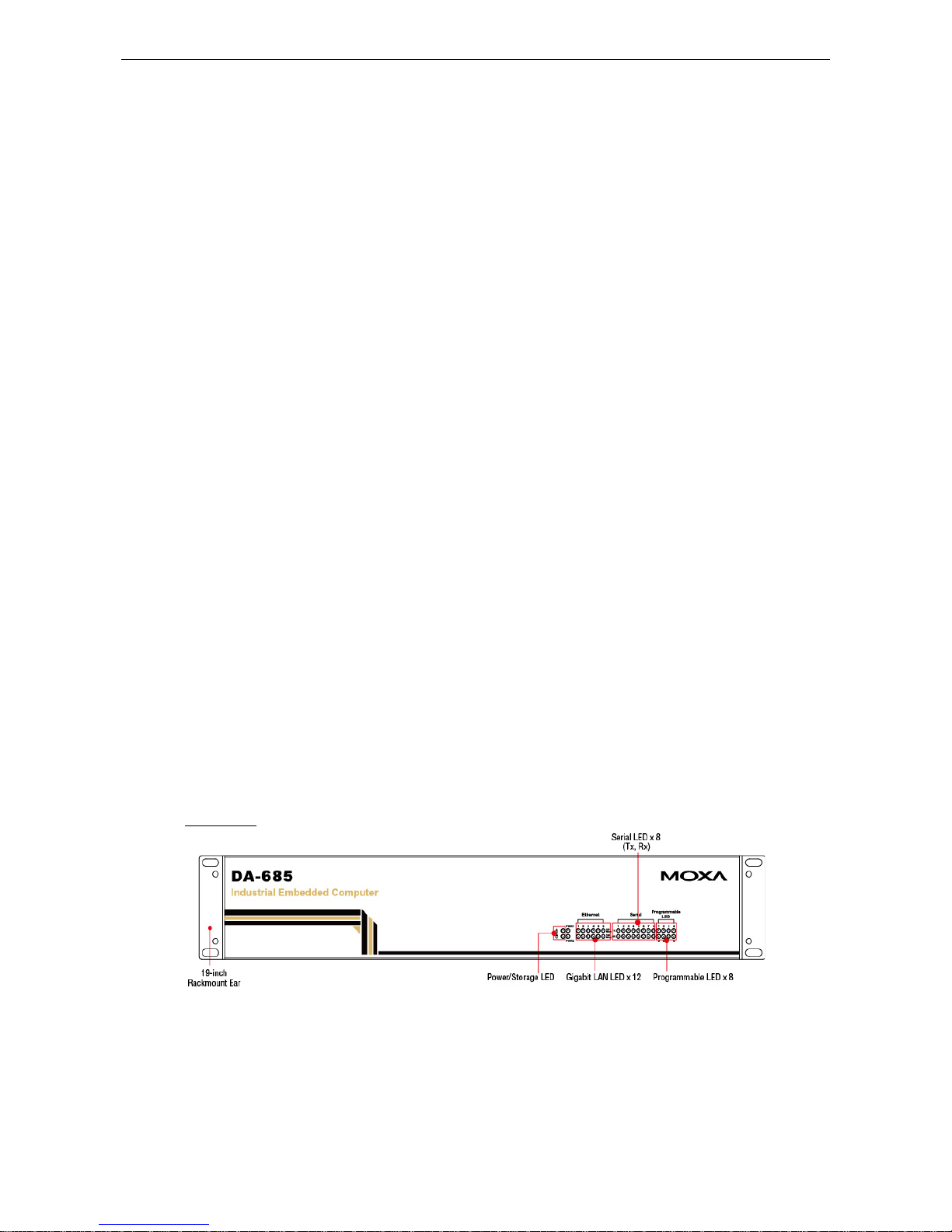
Appearance
Front View
Page 6
DA-683 Series Introduction
1-3
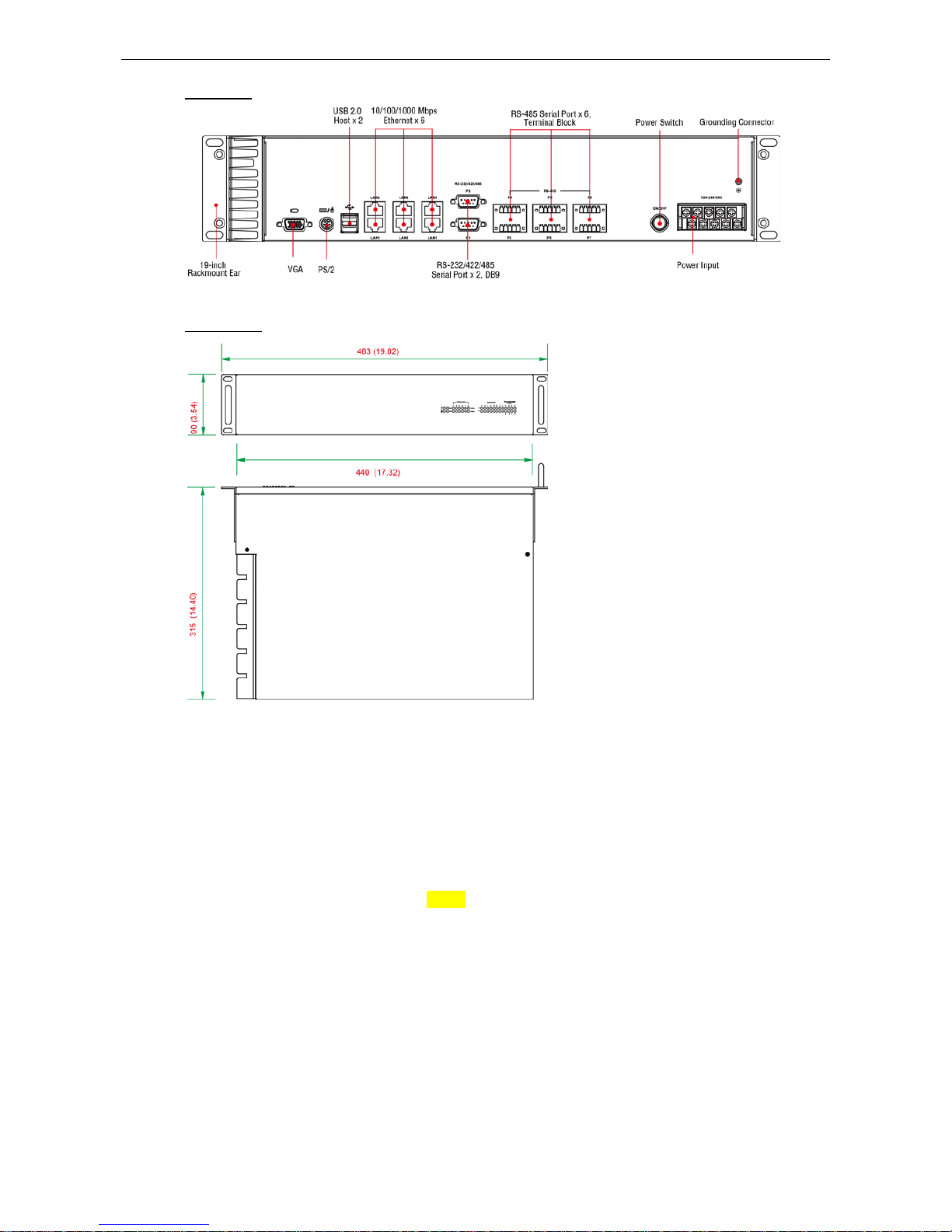
Rear View
Dimensions
Features
The DA-685 computer has the following fe a tures :
Intel Atom D510 1.66 GHz processor
1 DDR2 SODIMM sockets supporting DDR2 667 up to 2 GB (max.)
6 10/100/1000 Mbps Ethernet ports
2 selectable RS-232/422/485 DB9 (male) ports
6 two-wire RS-485 serial ports (terminal block)
2 USB 2.0 ports for high speed peripherals
CompactFlash socket for storage expansion
1 SATA connector for storage media (HDD/SDD) expansion
EMC Level 4 certified
Page 7
DA-683 Series Introduction
1-4
ATTENTION
R
efer to the “Non-standard Baudrates” section for instructions on how to calculate which baudrates are
supported
.
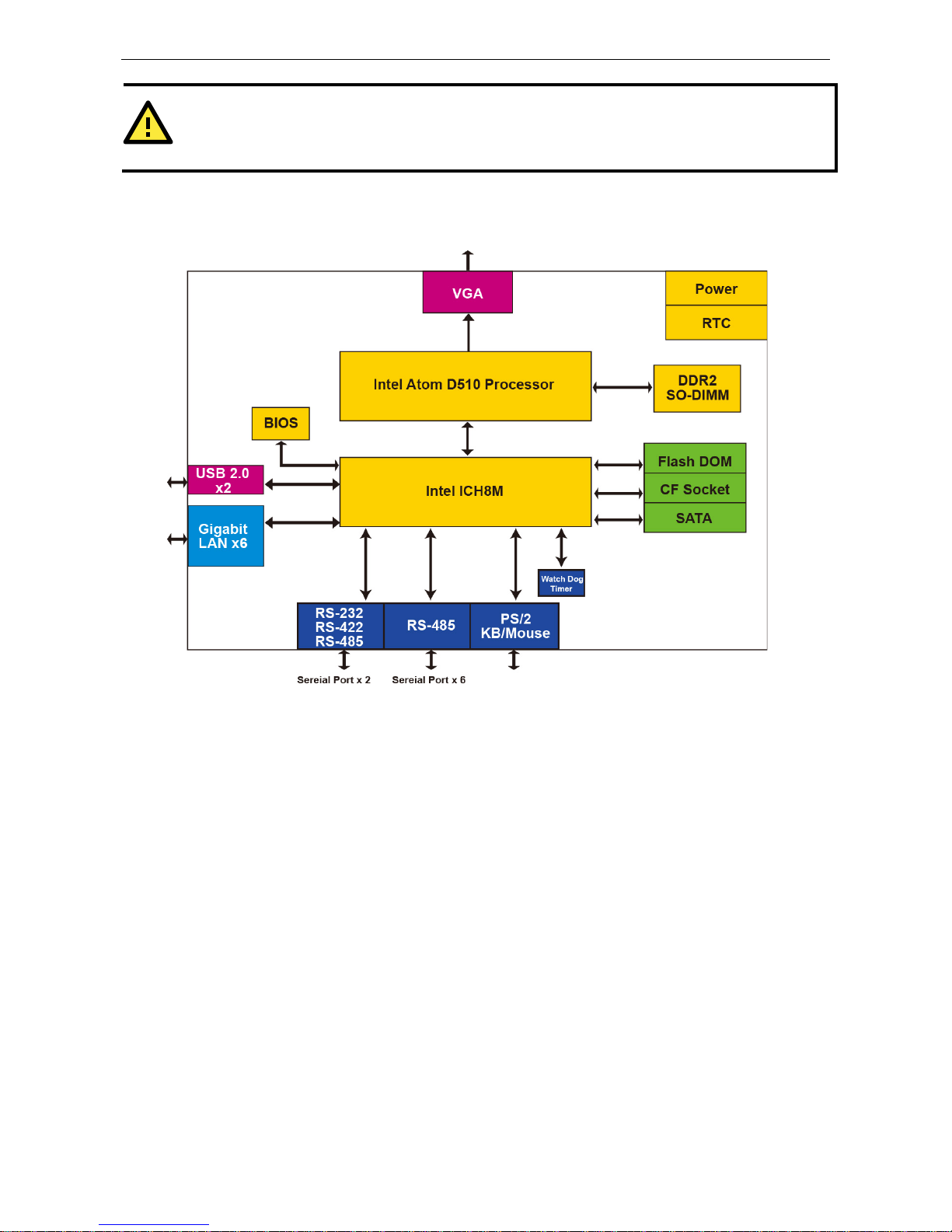
Hardware Block Diagram
Hardware Specifications
Computer
CPU: Intel Atom D510 1.66 GHz processor
OS: Linux, Windows 7, Windows XP Professional, or Windows Embe dded Standa rd 2009 (must be
installed by the user)
System Chipset: Intel Pinev iew -D + ICH8M
BIOS: 16 Mbit Flash BIOS, PCI Plug & Play, ACPI function support
FSB: 667 MHz
System Memory: 1 200-pin DDR2 SODIMM socket supporting DDR2 667; up to 2 GB, with 1 GB built in
USB: USB 2.0 compliant ports, Type A connector x 2, supports system boot up
Storage
Built-in: 2 GB industr ia l DO M onboard to store OS
Storage Expansio n: CompactFlash socket for CF card expansion, s up porti ng CF Type-I/II
HDD Support: 1 SATA connector for HDD expansion
Other Peripherals
KB/MS: 1 PS/2 interface, supports standard PS/2 keyboard and mouse through Y-type cable
Display
Graphics Controller: Intel® GMA3150 graphics controller on Intel D510 card
Display Interface: VGA output (DB 15 f emale conne c tor )
Resolution: CRT display mode with pixel resolution up to 2048 x 1536 at 75 Hz
Page 8

DA-683 Series Introduction
1-5
Ethernet Interfac e
LAN: 6 auto-sensing 10/100/1000 Mbps Gigabit ports
Magnetic Isolatio n Pr ote c t i on: 1.5 KV built-in
Serial Interface
Serial Standards:
• 2 selectable RS-232/422/485 ports (DB9 male)
• 6 2-wire RS-485 ports (terminal block)
Serial Signals
RS-232: TxD, RxD, DTR, DSR, RTS, CTS, DCD, GND, RI
RS-422: TxD+, TxD-, RxD+, RxD-, GND
4-wire RS-485: TxD+, TxD-, RxD+, RxD-, GND
2-wire RS-485: Data+, Data-, GND
LEDs
System: Power, Storage
Gigabit LAN (GbE): 100M x 6, 1000M x 6
Serial: TX/RX
Programmable: LED x 8
Switches and Buttons
Power Switch: on/off (on rear panel)
Physical Characteristics
Housing: SECC sheet metal (1 mm)
Weight: 4 kg
Dimensions: 315 x 440 x 90 mm (12.40 x 17.32 x 3.54 in) (without rackmount ears)
Mounting: Standard 19-inch rackmount
Environmental Limits
Operating Temperature: -10 to 55°C (14 to 131°F)
Storage Temperature: -20 to 80°C (-4 to 176°F)
Ambient Relative Humidity: 5 to 95% (non-condensing)
Anti-vibration: 2 g rms @ IEC-68-2-34, random wave, 5-500 Hz, 1 hr per ax is
Anti-shock: 20 g @ IEC-68-2-27, half sine wave, 11 ms
Power Requirements
Input Voltage: 100 to 240 VAC, 47/63 Hz, 0.6-0.3 A
Power Consumption: 40 W
Standards and Certifications
Safety: LVD, UL, cUL, CCC
EMC: FCC, CE (Class A)
Reliability
Alert Tools: Built-in buzzer and RTC (real-time clock) with lithium backup battery
Automatic Reboot Trigger: Built-in WDT (watchdog timer) supporting 1-255 level time interval system
reset, software programmable
Warranty
Warranty Period: 3 years
Details: See www.mox a .c om/war r a nty
Page 9

2
2. Hardware Installation
The DA-685 Series o f e le c trical substation computers are compact and rugged, making them suitable for any
industrial application that requir e s EMC Leve l 4 complianc e . The LED ind ic a tor s allo w users to mo ni tor
performance and identify trouble spots quickly, and multiple ports are provided for connecting a variety of
different devices. The DA-685 hardware platform is stable, reliable, and easy to maintain, allow ing you to
spend your time on application development rather than troubleshooting networking bugs. This chapter
describes the hardware installation and interfaces of DA-685 substation computers.
The following topics are covered in this chapter :
Placement Options
Desktop
R ac k mounting
Wiring Requirements
Connecting the Power
Wiring the Power Inputs
Power Input Wiring Description
HIPOT (Dielectric Strength) Testing
Front Panel LED
Connecting to a Displ ay
Connecting a PS/2 Keyboard and Mouse
Connecting USB Devices
Connecting Serial Devices
LAN Ports
Upgrading the Memory Module
Installing a Compac tF las h C ar d
Installing a SATA Hard Disk
Upgrading a DOM
Page 10
DA-683 Series Hardware Installation
2-2
Placement Options
Desktop
Place your DA-685 on a clean, flat, well-ventilated desktop. For better ventilation, leave some space between
the DA-685 and other equipment. Do not place equipment or objects on top of the DA-685, as this might
damage the computer’s internal components .
Rack mounting
The DA-685 has rackmount supports for installing the e mbe d ded computer into a standard 19” rack.
ATTENTIONS
For maximum safety, at least two persons should work together to lift, place, and
fasten the
computer to the
rack.
Before you lift or move the computer,
first verify both it and any power to the rack system is turned off.
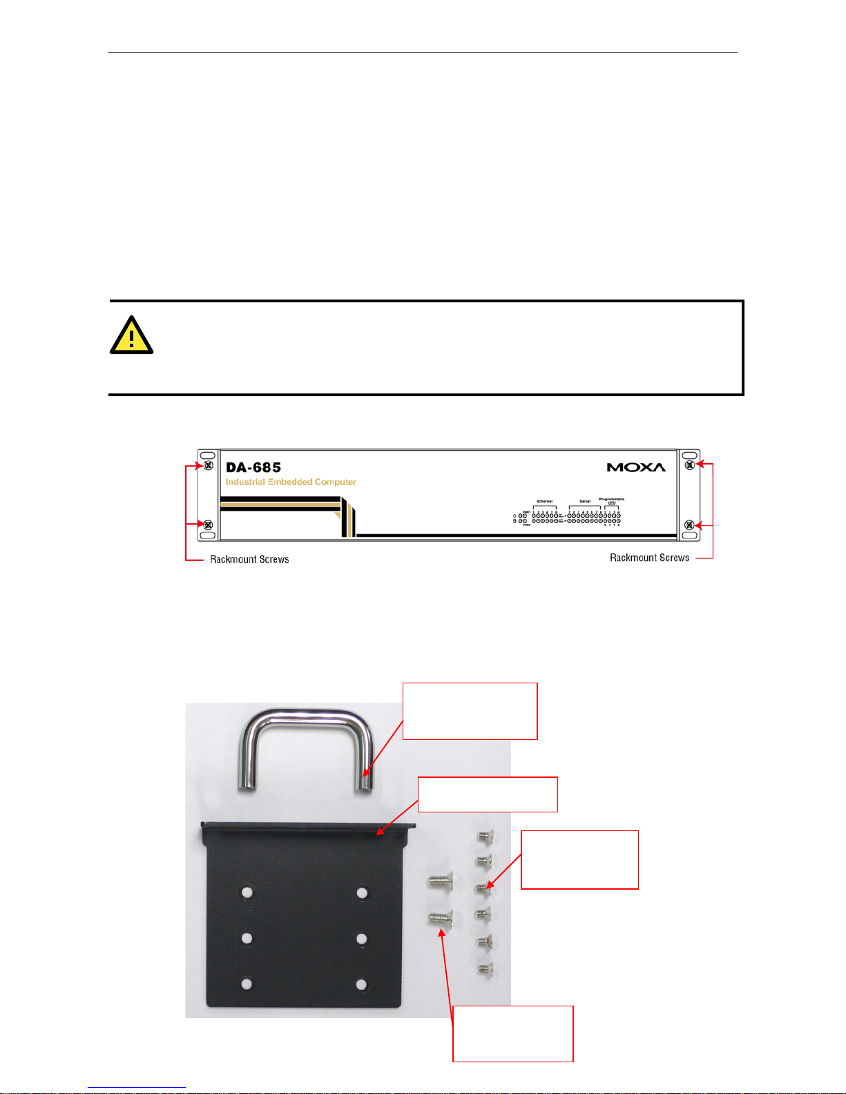
After installing the rackmount asse mbly (ears , hand le s ), four screws are required to fasten the DA-685 to a
rack.
Follow these steps to mount the DA-685 on a rack:
Step 1: Installing the rack supports (ears)
The rackmount assembly should be included with your DA-685. If you do not find the assembly package
please contact a Moxa representative for rectific a tio n. Each assembly should contain 2 rack ears and 12
FMSM4X6 screws. Please note that the handle and the FMSM5X10 screws are not included in the standard
rackmount assembly; these are optional acce ssor ie s tha t come sep ara te ly . If yo u are inter e s ted , p le ase
contact Moxa for ordering information.
Rack handle
Rack ear
6 FMSM4X6
screws
2 FMSM5X10
screws
Page 11

DA-683 Series Hardware Installation
2-3
Step 2: Installing a rackmount handle (optional) to a rack ear
Use 2 FMSM5X10 screws to attach the rackmount handle to the ear, as shown.
Step 3: Installing the rack ears to the DA-685
For each side panel of the DA-685, use 6 FMSM4X6 screws t o affix the ear to the DA-685, as shown below.
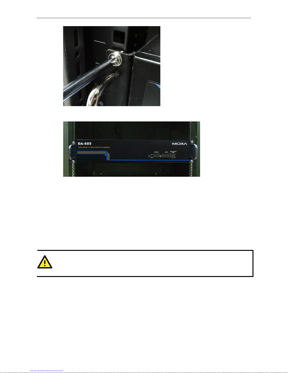
Step 4: Installing the DA-685 to a rack
Gently slide the DA-685 onto the rack and use the mounting screws provided by the rack supplier to affix
the DA-685 in place.
NOTE
Four screws are required to attach the DA-685
to the rack. Use two screws on the left side and two screws on
the right side.
Page 12
DA-683 Series Hardware Installation
2-4
As a final check, make sure that the computer is snugly affixed in pl ace.
Wiring Requirements
The following common safety precautions should be observed before installing any electronic device:
• Strive to use separate, non-intersecting paths to route power and network ing wire s . If powe r wiring and
device wiring paths must cross, make sure the wires are perpendic ular at the intersection point.
• Keep the wires separated according to interface. The rule of thumb is that w iring that s hare s simil ar
electrical characteristic s may be bundled together.
• Do not bundle input wiring with output wiring sep arate .
• When necessary, it is strongly advised that you labe l wir ing to all d evic es in the syste m .
ATTENTION
Do not run signal or communication wiring and power wiring in the same conduit. To avoid interference, wires
with different signal characteristic s
(i.e., different interfaces) sho uld b e route d separately.
Page 13

DA-683 Series Hardware Installation
2-5
ATTENTION
Safety First!
Be sure to disconnect the power cord before installing and/or
wiring your device.
Caution!
High Electrical Curren t!
Calculate the maximum possible current
for
each power wire and common wire. Observe all electrical codes
dictating the maximum current allowable for e ac h wire si ze .
If the current goes above the
maximum ratings, the wiring could overheat, causing serious damage to your
equipment.
Caution! High
Temperatures!
Be careful when handling the unit. When the unit is plugged in, the internal components generate
a lot of
heat
which may leave
the outer casing too hot to touch.
Connecting the Power Supply
The DA-685 offers both single power and dual power inputs. Use a screwdriver to remove the screws. Connect
the power cord to the screws and then attach the screws to the unit. For single models (SP), use Power 1 only;
for dual power models (DPP-T), use both Power 1 and Power 2 for power input insta llation. Refer to the
following figure for detailed information.
Page 14

DA-683 Series Hardware Installation
2-6
Wiring the Power Inputs
Page 15

DA-683 Series Hardware Installation
2-7
Power Input Wiring Description
Read the following section for a detailed power input wiring des cri p tion.
Terminal Number Description Note
1 PWR1 Line
PWR1 Line
+ is connected, or to the Line terminal
for the AC power source.
2 PWR1 Neutral
PWR1 Neutral – is conne c ted to the Neutr al
terminal for the AC power source.
3 PWR1 Surge Ground
PWR1 Surge Ground is connected to the Chassis
Ground via a jumper on the terminal block. Surge
Ground is used as the ground conductor for all
surge and transient suppression circuitry. NOTE:
Surge Ground must be disconnected from Chassis
Ground during HIPOT (dielectric stre ngth) tes ting.
4 Chassis Ground
Chassis Ground is connected to the Safety
Ground terminal for AC inputs, chassis ground
connects to both power supply surge grounds via a
removable jumper.
For AC Power Input
1. PWR1 Line should be connected to AC (Line).
2. PWR1 Neutral should be connec te d to AC (Neutral).
3. Surge Ground is connected to the Chassis Ground via a braided cable or other appropriate grounding wire.
Surge Ground is used as the ground conductor for all surge and transient suppression circuitry internal to
the protection board.
4. Chassis Ground should be connecte d to the AC Ground terminal.
ATTENTION
1. Equipment must be installed according to the applic able country wiring codes.
2. Surge Gro und MUST be disconne c te d fro m the Chassis Ground d uring HIPOT (dielectric strength)
testing.
3. All line-to-gr o und tr a ns ie nt e nergy is shunte d to the Surg e Gro und termina l. In cases where users
require the inputs to be isolated from the ground, remove the ground braid b e twee n Surge and
Chassis Ground. Note that all line-to-ground trans ie nt pr otection circuitry will be disabled.
HIPOT (Dielectri c Strength) Testing
Before performing the HIPOT test, you MUST have the jumpers removed and the br aided ground c able
disconnected. This is required to prevent the transient/surge suppression circuitry, which is connected to Surge
Ground from being activated during the HIPOT test.
Page 16

DA-683 Series Hardware Installation
2-8
When finished, press the Power Switch button to start the system. It will take about 30 to 60 seconds for your
operating system to boot up.
Front Panel LED
There are 40 LED indicators on the front panel. Information about each LED is given in the following table. The
additional ports LEDs, named Port 1 and Port 2 are temporarily re s erve d for future use.
LED Name Color LED Description
Power
Green Power is on
Off No power input or power e rror
Storage
Yellow / Blinking Data is being written to or to read from the storage unit
Off Storage unit is idle
Ethernet Port
100 Mbps
Green 100 Mbps of Ethernet Port is active
Off No activity
Ethernet Port
1000 Mbps
Yellow 1000 Mbps of Ethernet Port is active
Off No activity
Serial Port
TX 1-8
Green Serial port is trans mitting data
Off No operation
Serial Port
RX 1-8
Yellow Serial port is receiving data
Off No operation
Programmable
Port 1-8
Green Defined by users
Yellow Defined by users
Power Fail 1
Unused -Unused --
Power Fail 2
Unused -Unused --
Page 17

DA-683 Series Hardware Installation
2-9
Connecting to a Display
The DA-685 comes with a D-Sub 15-pin female connector on the front panel to connect a VGA monitor. To
ensure that the monitor image remains clear, be sure to tighten the monitor cable afte r conne c ting it to the
DA-685 computer. The pin assignments of the VGA connector ar e show n below .
DB15 Female Connector
Pin No. Signal Definit ion Pin No. Signal Definition
1 Red 9 VCC
2 Green 10 GND
3 Blue 11 NC
4 NC 12 DDC2B Data
5 GND 13 HSYNC
6 GND 14 VSYNC
7 GND 15 DDC2B Clock
8 GND
Connecting a PS/2 Keyboard and Mouse
Your DA-685 embedded computer comes with a PS/2 mini-DI N conne c tor to co nnect to a PS/2 keybo ard and
PS/2 mouse by using a Y-type cable. This 6-pin mini-DIN connector has the pi n assig nm ents shown below.
Pin No. Signal Definition
1 PS/2 Keyboard Data
2 PS/2 Mouse Data
3 GND
4 VCC
5 PS/2 Keyboard Clock
6 PS/2 Mouse Clock
Use the Y-type cable to convert the mini-DIN connector into two 6-pin mini-DIN connectors to connect both a
PS/2 keyboard and PS/2 mouse at the same time. (The Y-type cable is not included in the accessory package.
It should be purchased separately. You may also use the USB ports to connect your USB-based keyboard and
mouse.)
Page 18

DA-683 Series Hardware Installation
2-10
ATTENTION
Please note that without the Y-type cable, the PS/2 connecto r o n the DA-685 can only work with a PS/2
keyboard. A PS/2 mouse will not function when directly connected to the PS/2 connector on the DA-685
embedded comput er.
Connecting USB Devices
The DA-685 embedded computer has two USB 2.0 ports: two are on the front panel, and two are on the rear
panel. All of the ports are UHCI, Rev 2.0 compliant and support Plug & Play and hot swapping. These ports can
be used to connect USB devices, such as a keyboard, mouse, USB flash disk, and USB CD-ROM. In addition,
both USB ports support system boot up, which can be activated by modifying the BIOS settings. The c hapte r
“BIOS Setup” describes the configuration process in detail.
Connecting Serial Devices
The DA-685 comes with two RS-232/422/485 serial ports with DB9 male connectors, and six RS-485-2w serial
ports with terminal blocks. See the following figure for the location of the serial ports on the rear panel.
The pin assignments for RS-232/422/485 serial ports are shown in the following table:
DB9 Male Port RS-232/422/485 Pinouts
Pin RS-232 RS-422 RS-485-4W RS-485-2W
1 DCD TxDA(-) TxDA(-) –
2 RxD TxDB(+) TxDB(+) –
3 TxD RxDB(+) RxDB(+) DataB(+)
4 DTR RxDA(-) RxDA(-) DataA(-)
5 GND GND GND GND
6 DSR – – –
7 RTS – – –
8 CTS – – –
Page 19

DA-683 Series Hardware Installation
2-11
The pin assignments for RS-485-2w serial ports are show in the foll o w i ng tabl e :
Terminal Block Port RS-485-2w Pinouts
Pin RS-485-2W
1 –
2 –
3 DataB(+)
4 DataA(-)
5 GND
LAN Ports
The DA-685 has 6 10/100/1000 Mbps LAN ports. When the cable is properly connected, the LEDs on the front
panel will glow to indicate a proper connectio n.
Pin No. 100 Mbps Signal 1000 Mbps Signal
1 ETx+ TRD (0)+
2 ETx- TRD (0)3 ERx+ TRD (1)+
4 -- TRD (2)+
5 -- TRD (2)6 ERx- TRD (1)7 -- TRD (3)+
8 -- TRD (3)-
LED Color Description
Ethernet Port
1000 Mbps
Yellow 1000 Mbps of Ethernet Port is active
Off No activity
Ethernet Port
100 Mbps
Green 100 Mbps of Ethernet Port is active
Off 10 Mbps or no activity
The default IP addresses and netmasks of the Gigabit LAN ports are as follo ws:
Default IP Address Netmask
LAN 1 192.168.3.127 255.255.255.0
LAN 2 192.168.4.127 255.255.255.0
LAN 3 192.168.5.127 255.255.255.0
LAN 4 192.168.6.127 255.255.255.0
LAN 5 192.168.7.127 255.255.255.0
LAN 6 192.168.8.127 255.255.255.0
NOTE Please note that the XPE models use DHCP.
Page 20

DA-683 Series Hardware Installation
2-12
Upgrading the Memory Module
The DA-685 embedded computer suppo rts one 200-pin DDR2 667 SODIMM module of up to 2 GB. One DDR2
SDRAM memory module is pre-installed . To upgrade the DDR2 SDRAM memory module, follow these
instructions:
1. Disconnect the DA-685 from the power source.
2. The DA-685’s memory module is located
inside the DA-685. Use a screwdriver to remove
the screws on the top cover of the DA-685.
3. After removing the
cover, you will see
the DDR2 SDRAM
module.
4. To upgrade the
memory, you need to
remove the original
memory by pushing
two clutches at both
sides of the module.
5. Gently insert the
new memory into the
module. Make sure
the direction is
correct.
Page 21

DA-683 Series Hardware Installation
2-13
6. Push the memory
all the way down to
complete installation.
Installing a CompactFlash Card
The DA-685 embedded computer comes with a CompactFlash socket. To insert a CompactFlash c ard , follo w
these instructions.
1. Disconnect the DA-685 from its power source.
2. The DA-685’s CompactFlash socket is located inside the DA-685. Use a screwdriver to remove a ll the screws
on the top cover of the DA-685.
3. Insert the CompactFlash card into the socket. Push downwards to make sure that the card is firmly inserted.
ATTENTION
Make sure you insert the card
in the right direction – do not force the card
. The card cannot be inserted if you
insert the card in
correctly.
ATTENTION
The
DA-685 em bedded compu ter does not support CompactFlash hot swap and PnP
(Plug and Play). It is
first
necessary to remove the power source before inserting or removing the CompactFlash card .
Page 22

DA-683 Series Hardware Installation
2-14
Installing a SATA Storage Drive
The DA-685 embedded computer features a single SATA connector for SATA storage drives. To install a
2.5-inch SATA storage drive (SSD or HDD) a DA-685 storage drive mounting assembly must be acquired (it is
not included in the basic DA-695 packaging). To install a storage drive, follow these instr uc tio ns :
1. Disconnect the DA-685 from its power source
2. Open the top cover of the
DA-685; the following
figure shows the specific
location where the storage
drive will be mounted:
3. Retrieve the mounting
bracket from the storage
drive mounting kit and
affix it to the drive via the
bracket’s sid e pane l s ,
using two screws:
4. Connect the power cable
and the SATA cable to the
storage drive:
5. Place the drive bracket
into the mounting space;
fasten the bracket to the
case using four screws,
one on each corner
Page 23

DA-683 Series Hardware Installation
2-15
6. Connect the power cable
and SATA cable to the
motherboard, as follows:
ATTENTION
The SATA
storage drive mounting assembly – which includes the SATA data and power cables –
does not ship
with the basic models
of the DA-685 embedde d co mputer. For purchasing information, please contact Moxa.
Upgrading a DOM
The DA-685 comes with an IDE-based DOM in which the operating system has been installed. To upgrade this
DOM, follow these steps.
1. Disconnect the DA-685 from its power source.
2. Open the top cover of the
DA-685. Refer to the
following figure for the
specific location for the
DOM installation.
3. Remove and pull up the DOM carefully.
4. Insert the new DOM and
push downwards to finish.
Page 24

3
3. BIOS Setup
This chapter describes the BIOS settings of the DA-685 computer. The BIOS is a set of input/output c ontrol
routines for peripherals. The BIOS is used to initializ e b as ic p eripherals and loads the operating system. The
BIOS setup allows the user to modify the system configurations of these basic input/output peripherals. All of
the configurations will be stored in the NVRAM (flash memory), which re tains the sys te m infor m ation after
system reboots or the power is removed.
The following topics are covered in this chapter :
Entering the BIOS Setup Utility
Main Information
Modifying the BIOS Main Settings
Advanced Settings
Se c urity Settings
Power Settings
Bo ot Settings
Ex it S e ttings
Upgrading the BIOS
Page 25

DA-683 Series BIOS Setup
3-2
Entering the BIOS Setup Utility
To enter the BIOS setup utility, press the “F2” key while the system is booting up. The main BIOS Setup screen
will appear.
A basic description of each function key is listed at the bottom of the screen. Refer to these descriptions to learn
how to use them.
F1: General Help
F5/F6: Change Values
F9: Setup Defaults
F10: Save and Exi
↑↓
: Select Item
← →
: Select Menu
ESC: Exit
ENTER: Select or go to Submenu
BIOS Main Page
The main page of the BIOS displays basic low-level information about system hardware, including thing s like
model names, CPU typ e, and BIOS version.
Page 26

DA-683 Series BIOS Setup
3-3
Modifying BIOS Settings
Navigate the BIOS menus using the arrow keys; up (↑) and down (↓) arrows navigate the menu, while left (←)
and right (→) arrows will open or close sub-menus from entries marked with a triangle (▲) at the beginning of
the line.
Advanced Settings
The “Advanced Features” screen will appear when choos i ng the “Advanced” item from the main menu.
Boot Configuration
This item allows users to toggle the number pad into “on” or “off” when first boo ting up.
Page 27

DA-683 Series BIOS Setup
3-4
Peripheral Configuration
The Debug Port item under P eripheral Co nfiguratio n allows you to select an alternate debugging interrupt.
Please note that this should be used only by programmers who are familiar with debugging.
Options: 2E8/IRQ6, Disabled (default)
IDE Configuration
This item allows you to configure the storag e driv e controllers.
HDC Configure As
This item allows you to configure the storage driv e type. The options are:
AHCI (default); PATA; SATA; and IDE Non-Combined
Page 28

DA-683 Series BIOS Setup
3-5
Channel Master 1 to 3
This setting displays the storage devices installed on the computer’s master bus. These storage devices may be
DOMs, HDDs, SSDs, or a CF card.
Channel Slave 1 to 3
This setting displays storage devices installed on the computer’s slave bus. These storage drives may be DOMs,
HDDs, SSDs, or a CF card.
Video Configuration
This item allows you to configure the video settings.
IGD – Pre-Allocated
This item allows you to configure the pre-allo c a te d cap acity for the graphic me mory capacity.
Options: 8 MB (default), 1 MB
IGD – DVMT Size
This item allows you to configure the capacity of the DVMT 5.0 used by the internal graphics device.
Options: 64 MB (default) , 128 MB, 224 MB
Page 29

DA-683 Series BIOS Setup
3-6
USB Configuration
This item allows you to turn USB Legacy mode on or off. USB Legacy allows older USB devices to be accessed
from the earliest boot initialization, and/or DOS.
Options: Enabled (default), Disable d
ACPI Table/Features Control
This item allows you to configure FACP and HPET func tio ns .
Page 30

DA-683 Series BIOS Setup
3-7
FACP – RTC S4 Wakeup
This item allows you to enable RTC wakeup, so the computer may pull itself out of sleep or hibernation mode
to perform specified tasks at a certain time each day.
Options: Enabled (default), Disable d
HPET – HPET Support
This item allows you to enable/disable the HPET (High Precisio n Ev e nt Ti mer ), which produces periodic
interrupts at a much higher resolution than the RTC and may be used to synchronize multimedia streams. HPET
can sometimes introduce system instabili ty , s o some users may wis h to dis able it.
Option: Enabled (default), Disabled
Base Address Select
This allows you to select the memory address range for the HPET.
Options: FED00000h (default), FED01000h, FED02000h, FED03000h
Hardware Monitor
This item allows you to view various self-reported hardware states that include CPU temperature , sys te m
temperature, and CPU voltage.
Page 31

DA-683 Series BIOS Setup
3-8
Security Settings
The section allows users to configure security settings like a system supervisor password and u ser password.
Set Supervisor Password
This item allows you to set the supervisor password. Select and then enter the password, and then confirm the
password again.
Set User Password
This item allows you to set the user passwor d . Select and the n ente r the pass wor d , and then co nfir m the
password again.
Set All HDD Password
This item allows you to set the password for all storage devices on your computers, including CF, DOM and hard
disk. You need to enter the password when booting up to use these storage dev i ces.
Set All Master HDD Password
This item allows you to set the password for the master storage drive on your computer. You need to enter the
password when booting up to use the master hard disk.
Page 32

DA-683 Series BIOS Setup
3-9
Power Settings
The section allows users to configure power se tting s .
Advanced CPU Control
Thermal Mode
This item enables Intel’s thermal throttling 1 technology in the CPU; it functions as a temperature trip that will
throttle the CPU (and thereby decrease performanc e ) when a certain tem p er ature is reached. Enabling this
function allows you to configure the ther ma l contro l circ uit in the op era ting sy s te m userspac e .
Options: TM1 (default), Disabled
HT Support: Hyper-Threading Technology
This item enables Hyper-Threading (HT) technology, so that the CPU may utilize simultaneous multithreading.
This improves performance for multi-threaded code and gives improved reaction and response time. However,
in some instances users may want to disable it to conserve power or reduce CPU cac he paging .
Options: Enable (default), Disabl e d
Use XD Capability
This item allows you to enable/disable the Intel XD functio n, which provides executable space protection by
toggling the NX bit in memory spaces designated as data. This gives a strong pro te c tion against buffer
overflows by preventing the execution of malicious code that has been delivered into memory space in a hidden
data packet. It is strongly advised to enable XD technolog y.
Options: Disabled (default), Enable
Page 33

DA-683 Series BIOS Setup
3-10
ACPI S3
This item allows you to enable/disable Processor Pe rf or ma nce S tate s (P-State s ) f unc tion; this technology is
primarily intended for power conserva tio n on lap top s . By default, it is ena b led .
Options: Disabled, Enabled (default).
PWRON After PWR-Fail (Power on after Power Fail)
This item allows you to configure the computer to turn its e l f ba ck on after a power failure. If a power failure
occurs and Enabled is chosen, the computer will automatically po wer up , regard less if it was on or not when
the failure occurred. If Last State is chosen, the computer will power up if it had been on, or will remain off if
it was not on when the failure occurred.
Options: Disabled, Enabled (Default), Last S tate .
Auto Wake on S5
This item allows you to configure the computer to wake from S5 status. S5 stands for Soft Off, where the PSU
remains engaged but power to all other parts of the system is cut. Auto-wake on S5 schedu les a soft-reboot at
certain periodic times that may be specified in the BIOS.
Options: Disabled (default); By Every Day (user specifies a regular daily time when the computer will power
up); By Day of Month (user specifies a regular day each month when the computer will power up)
Boot Settings
The section allows users to configure boo t setting s .
Page 34

DA-683 Series BIOS Setup
3-11
UEFI Boot
This item allows you to enable/disable the Unified Exten sible Fir mware In terface , which allows for remote
diagnostics and repair of computers even without an operating system. Users who ar e con cerned a bout safet y
or ownership issues may disable it.
Options: Enabled (default), Disable d
Quick Boot
This item allows you to enable/disable quick book functio n to reduce OS loading times.
Options: Enabled (default), Disable d
PXE Boot to LAN
This item allows you to configure the Preboot eXecution Environment‘s boot-to-LAN function. PXE provides
an independent boot environment that may be initialized ov e r a networ k inte rface, without intermediary
storage devices or local operating systems.
Options: Disabled (function), enab le d
USB Boot
This item allows you to enable/disable the system to boot from a USB storage device or network connection.
Options: Enabled (default), Disabled
WDT Timeout
This item allows you to enable/disable the watchdog time r and conf ig ure its time to tr igg ering. Watchdog
timers receive messages from code that is being executed in memory, and whe n a hang occurs will
automatically restart the system to clear the hung proc e ss fro m memory.
Options: Disabled (default), 1 to 10 minutes .
Boot Redirection
This item allows you to choose alternate storage and networking media to which the computer will turn
following a watchdog timeout.
Options: Disabled (default), CF (CompactFlash), USB, LAN.
Please note that if you select LAN as the boot sour ce then PXE/Boot-to-LAN must be enabled.
EFI
This item displays the boot selection for the UEFI boot func tio n.
Legacy
Normal Boot Menu
This item allows you to configure the boot menu.
Options: Normal (default), Advanced
Page 35

DA-683 Series BIOS Setup
3-12
Boot Type Order
This item allows you to select the order in which the computer will search storage devices for bootable images;
the highest device on the list will be searched first, the n the se cond , a nd so on until the computer finds a
bootable image. F5/F6 will allow you to change the boot order.
Options: Hard Disk Drive (default), CD/DVD-ROM Dri ve, USB, Othe rs.
Hard Disk Drive
This item allows you to view information returned by the storage device (SSD, HDD) installed in the computer.
USB
This item allows you to view information about any USB device connected to the computer.
Exit Settings
The section allows users to exit the BIOS.
Exit Saving Changes
This item saves the values you have just configured and exits the BIOS.
Options: Yes (default), No
Save Change Without Exit
This item saves changes but does not exit the BIOS.
Options: Yes (default), No
Exit Discarding Changes
This item allows you to exit the BIOS without saving any new settings fr om the use r sess ion.
Options: Yes (default), No
Page 36

DA-683 Series BIOS Setup
3-13
Load Defaults Setting
This item resets the entire BIOS to factory default values.
Options: Yes (default), No
Load Custom Defaults
This item loads custom defaults across the entire BIOS.
Options: Yes (default), No
Save Custom Defaults
This item saves the current BIOS settings as the new custom defaults.
Options: Yes (default), No
Discard Changes
This item allows you to discard all settings you have jus t configur ed .
Options: Yes (default), No
Upgrading the BIOS
This section describes how to upgrade the BIOS. However, please note that it is easy to permanently damage
the computer when upgrading the BIOS. We strongly reco mmend that yo u contac t Mox a’s technic al supp or t
staff for assistance in order to obtain all necessary tools and the most current advice before attempting to
upgrade the BIOS on any Moxa device.
Step 1: Create a Bootable USB Disk.
Before upgrading the BIOS every user should first create a bootable USB RAM drive as a system rescue device.
A useful software suite for building USB RAM drives may be found by searching for HP USB Disk Storage
Format Tool, which may then be downloaded and used to create a bootable RAM drive.
To create a rescue system, you will also need to download the FreeDos system files kernel.sys and
command.com from http://www.freedos.org/kernel/.
Copy the DOS files kernel.sys and command.com to a specified directory (C:\FreeDOS in this example).
Start the HP USB Disk Storage Format Tool and in the drop-down menu labeled Device select the USB de vice
that you want to use as a bootable disk.
Configure it to use a FAT file system from the File System drop-down.
Enter a drive name in the Volume Label field.
Check the option Create a DOS Startup Disk under Format Options.
Specify the directory where the system files are located (for example, C:\FreeDOS).
Click Start to format and create the bootable USB drive.
Page 37

DA-683 Series BIOS Setup
3-14
ATTENTION
We suggest you use a USB drive with under 2 GB in disk space, as larger USB drives may not support the FAT
file format and
will consequently fail to boot.
Step 2: Prepare the Upgrade File.
You must use the BIOS upgrade installation file to upgrade the BIOS. You can send your reques t to Moxa ' s
technical support team at support@moxa.com to get an updated version of the BIOS.
1. Get the BIOS upgrade installa tio n file. The file name should have following format: 685xxSxx.exe (xx
refers to version numbers)
2. Copy the f il e to the Bootable USB Disk.
Step 3: Run the upgrade pr ogr a m o n the DA-685 computer
1. Reboot the computer and go to the Boot Manager by pressing F12 while booting up, before the operating
system has begun to load.
2. Select USB Disk as the first boot source. Press Enter to co ntinue.
Page 38

DA-683 Series BIOS Setup
3-15
3. Once the computer boots, a DOS screen will appear. Go to the directory where the upgrade file is located.
For example, if the upgrad e f ile is store d in the DA685 folder, type:
#:/cd DA685
C:\ cd DA685
4. Run the upgrade program by typing 68510S05.exe.
Please note that the upgrade filename may vary depending on the firmware version.
C:\ DA685>68510S05.exe
5. The upgrade program will run. Wait until the proc edure is finished before initiating any changes to the
system. Be patient; the upgrade will take quite a few minutes.
DO NOT ALLOW THE COMPUTER TO POWER DOWN! DO NOT REMOVE THE USB DRIVE!
6. Once the upgrade is finished, the computer will automatically reboot. To check and see if the up grade was
successful, navigate to the BIOS Main Page and note the BIOS Version numbe r.
ATTENTION
Do NOT switch off the power su pply duri ng
the BIOS upgrade. Doing so will likely cause
permanent
damage to your
system!
Page 39

A
A. Safety Installation Instructions
A. RTC Battery Warning
CAUTION: There is a risk of explosion if battery is replaced by an incorrect type . Dispo se of used b atteri e s
according to the instructions.
B. Fuse Warning
CAUTION: For continued protection against fire, repla c e only with same type and r ating of fus e .
C. Rackmount Warning
The following or similar rackmount instr uc tions are included with the installation instructions :
(1) Elevated Operating A mbient: If installed in a closed or multi-unit rack assembly, the operating ambient
temperature of the rack environment may be greater than the roo m ambient te mpe r a tur e. Therefore,
consideration should be given to installing the equipment in an environment compatible with the maximum
ambient temperature (Tma) specified by the manufacturer.
(2) Reduced Air Flow: Installation of the equipment in a rack should be such that the air flow required for
safe operation is not obstructed.
(3) Mechanical Loading: Mounting of the equipment in the rack should not create hazards that result from
uneven mechanical loading.
(4) Circuit Overloading: Consideration should be given to the connection of the equip ment to the power
supply and the effect that overloading of the circuits m ig ht have on over c urr e nt prote c tions or supply wiring.
Appropriate consideration of equipme nt namep late ratings must be noted when evaluating this co nc ern.
(5) Reliable Grounding: Reliable grounding of rack-mounted equipment should be maintained. Partic ula r
attention must be given to indirect power connections that do not directly link to the branch circuit (e.g., over
power strips).
D. High Temperature Warning
(1) This equipment is intended to be used in a Restricted Access location like a locked computer room.
Access to this equipment should only be granted to AUTHORIZED SERVICE PERSONNEL or to users who have
been instructed about the the potential heat hazard posed by the metal chassis. This computer can become so
hot that after a long period of operations users and service personnel must take special care to wear protective
clothing before touching it. Only AUTHORIZED PROFESSIONALS sh ou l d be allowed direct access to an
operating device.
(2) External metal parts can get dangerously hot!! Befo re touching it, give special attention to device
temperature! Protective wear will likely be necessary!
Page 40

B
B. Regulatory Statement Approval
This device complies with part 15 of the FCC Rules. Operation is s ub jec t to the follo w ing
two conditions: (1) This device may not cause harmful inte rf e re nc e , and (2 ) this device
must accept any interference received, including inte rference that may cause undesired
operation.
Class A: FCC Warning! This equipment has been tested and found to comply with the limits for a Class A digital
device, pursuant to part 15 of the FCC Rules. These limits are designed to prov id e r e asonable prote c tion
against harmful interference when the equip m e nt is operated in a commercia l e nvir onment. This equipment
generates, uses, and can radiate radio frequency energy and, if not installed and used in accordance with the
instruction manual, may cause harmful interfere nc e to radio communic a tio ns . Operation of this equipment in
a residential area is likely to cause harmful interference in which case the user will be required to correct the
interference at his own expense.
European Community
Warning:
This is a Class A product. In a domestic environment this product may cause radio interference in which case
the user may be required to take adequate measures.
 Loading...