

Moxa Technologies DA-683, DA-683-SP-XPE, DA-683-SP-LX, DA-683-DPP-T-XPE, DA-683-DPP-T-LX Quick Installation Manual
P/N: 1802006830011
DA-683 Quick Installation Guide
cond Edition, February 2011
ssor and
gabit Ethernet ports, 2 RS-232 serial ports,
dard 19-inch
rform many
sume little power, ensuring a cost-effective
r
tem
-installed),
icated
re support
ers
2.
mputer
rial Ports,
Flash, 4
to 60°C
puter
rial Ports,
ash, 4
perature
•
-Run
iga LANs,
rts, 4 DI + 4 DO, 2 Peripherals Expansion
mbedded
operating temperature
C
61850-3 x86 Ready-to-Run
ith 1.66GHz CPU, VGA, 6 Giga LANs, 2
RS-232 Serial Ports, 4 DI + 4 DO, 2 Peripherals Expansion
Slots, CompactFlash, 4 USB, Dual Power, Linux, -40 to 70°C
operating temperature.
Each basic system model is shipped with following standard items:
• DA-683 basic unit
• Quick Installat
ion Guide
• Document & Software CD
over cab
5 serial module with
serial module with
/485 serial module with
l isolation
485 serial module with
digital isolation
0 M
bps unmanaged switch
ps LAN module
niversal PCI development kit
expansion modules are currently un
development.
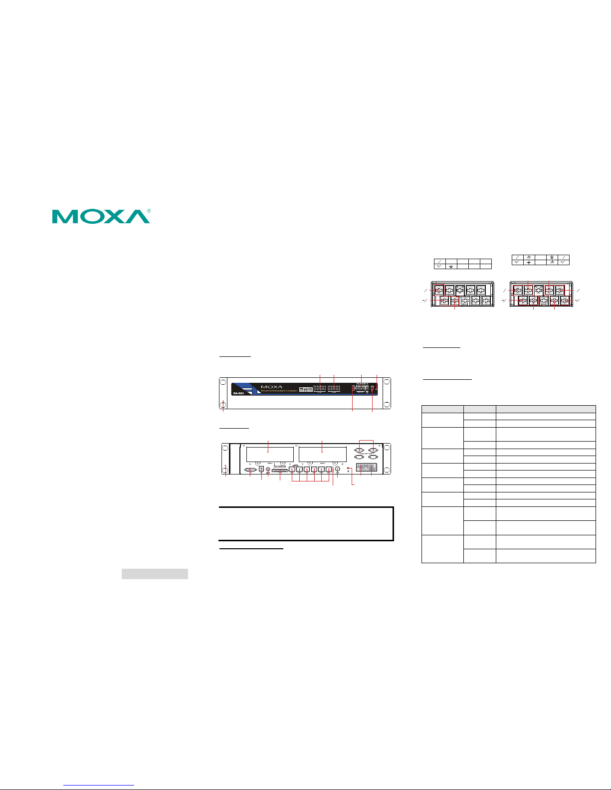
3. Hardware Installation
Front View
Se
1. Overview
The DA-683 computers are based on the Intel x86 proce
support DVI-I, 6 Gi
CompactFlash, and USB. The DA-683 comes in a stan
2U high form factor.
With the Core Duo processor, the DA-683 can pe
i
ndustrial tasks yet con
,
t
erminal block connector and
10
• DA-LN04-RJ: 4
-port 10/100 Mb
sol
ution for industrial applications. Two slots available fo
expansion modules provide the great flexibility in sys
integration and expansion.
The DA-683 runs Linux, or Windows XP Embedde
to provi
de a familiar environment for developing
application software. Moxa’s comprehensive softw
d (pre
sophist
a
lps programm
develop bug-free code quickly and at a lower cost.
Model Names and Package Checklis
he DA-683 Series includes the following models:
makes the prog
rammer’s job easier, and he
t
T
• DA-683-SP-XPE: x86 Ready-to
-Run Rackmount Co
with 1.66 GHz CPU, DVI-I, 6 Giga LANs, 2 RS-232 Se
4 DI + 4DO, 2 Peripherals Expansion Slots, Compact
ard, -10 USB, Single Power, Windows Embedded Stand
operating temperature
DA-683-SP-LX: x86 Ready-to-R
un Rackmount Com
with 1.66 GHz CPU, DVI-I, 6 Giga LANs, 2 RS-232 Se
•
4 DI + 4DO, 2 Peripherals Expansion Slots, CompactFl
USB, Single Power, Linux, -10 to 60°C operating tem
DA-683-DPP-T-XPE: IEC
61850-3 x86 Ready-to
Rackmount Computer with 1.66 GHz CPU, DVI-I, 6 G
2 RS-232 Serial Po
Slots, CompactFlash, 4 USB, Dual Power, Windows E
Standard, -40 to 70°C
• DA-683-DPP-T-LX: IE
Rackmount C
omputer w
le, 100 cm • Ethernet Cable: RJ45 to RJ45 cross-
• Product Warranty Statement
Optional Expansion Modules:
• DA-SP08-I-DB: 8-port RS-232/
422/4
DB9 connector and digital isolation
8
• DA-SP08-DB: 8-port RS-232/42
2/485
DB9 connector
• DA-SP08-I-TB: 8-port RS-232/
422
terminal block connector and digita
• DA-SP38-I-TB: 8-port RS-422/
• DA-SW08-RJ: 8-port 10/
modu
le
• DA-UPCI-DK: U
NOTE: Additiona
l der
19-inch Rackmount Ear
Module Slot B
LED x 16
(Serial/LAN)
LED (Power, Storage)
USB 2.0
Host x 2
Reset Button
Module Slot A
LED x 16
(Serial/LAN)
LED
(Programmable x 8)
(Serial, Tx x 2, Rx x 2)
(Gigabit LAN x 12)
Rear View
19-inch
Rackmount Ear
10/100/1000 Mbps
Ethernet x 6
RS-232 Serial Port x 2
(DB 9 Male)
Ground
DVI-I
PS/2
USB 2.0
Host x 2
Power
Input 1
Power
Input 2
Power
Switch
DI x 4, DO x 4
(Terminal Block)
Module Slot A Module Slot B
LED (Power, Storage)
NOTE Expansion modules can be installed
B. For example, in the above figu
in either Slot A or Slot
re the LAN port module
DA-LN04-RJ is installed in Slot A and the serial port module
DA-SP08-I-DB is installed in Slot B.
Connecting the Power
DA-683 offers both single power and dual power inputs. Please use
a screwdr
iver to remove the screws. Connect the power cord to the
screws, and then attach the screws to the unit. For single power
models (SP), use Power 1 only; for dual power models (DPP-T),
Refer to the following figure for
ed, press the Power Switch
to start the system. It will take about 30 to 60 seconds for
your operating system to boot up.
use both Power 1 and Power 2.
detailed information. When finish
button
PWR 1 PWR 2
+
L
+
L
N
N
NC
NC
DPP-T Models
Chassis Ground
Surge Ground
Power 1
Power 2
+
L
N
+
L
N
Surge Ground
Chassis Ground
SP Models
PWR 1
+
L
N
NC
NC
NC NC
NC
NC
NC
Power 1
+
L
N
Chassis Ground
For more detailed power connect
i
nformation, please refer to the
Reset Button
ion and surge protection
Hardware User’s Manual.
Pressing the Reset button initiate
button pl
ays the same role as a d
pressing the reset button, the sy
s a hardware warm reboot. The
esktop PC’s reset button. After
stem will reboot automatically.
sFront Panel LED
0 LED indicators on the front panel. Information about
ng table. Additional ports LEDs, Port
y reserved.
There are 6
each LED is given in the followi
1 and Port 2, are temporaril
LED Name Color LED Description
Green Power is on Power
Off No power input or power error
Yellow /
Blinking
Data is being written to or to read
from the storage unit
Storage
Off Storage unit is idle
Green 1000 Mbps of Ethernet port is active Ethernet Port
1000 Mbps
Off No activity
Yellow 100 Mbps of Ethernet port is active Ethernet Port
100 Mbps
Off 10 Mbps or no activity
Green Serial port is transmitting data Serial Port TX
1-2
Off No operation
Yellow Serial port is receiving data Serial Port RX
1-2
Off No operation
Green Serial port is transmitting data, or 100
Mbps Ethernet port is active
Module Slot A
Orange Serial port is receiving data, or 10
Mbps Ethernet port is active
Green Serial port is transmitting data, or 100
Mbps Ethernet port is active
Module Slot B
Orange Serial port is receiving data, or 10
Mbps Ethernet port is active
– 1 – – 2 – – 3 –
– 4 – – 5 – – 6 –
www.moxa.com/support
The Americas: +1-714-528-6777 (toll-free: 1-888-669-2872)
Europe: +49-89-3 70 03 99-0
Asia-Pacific: +886-2-8919-1230
China: +86-21-5258-9955 (toll-free: 800-820-5036)
2011 Moxa Inc., All Rights Reserved
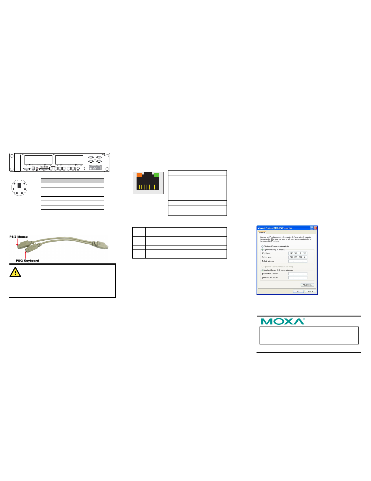
Connecting a PS/2 Keyboard and Mouse
Your DA-683 embedded computer comes with a PS/2 m
connector to con
nect to a PS/2 keyboard and PS
Y-type cable. This 6-pi
ini-DIN
/2 mouse with a
n mini-DIN connector has the pin
assignments shown below.
PS/2
12
4
6
5
3
Pin No. Signal Definition
1 PS/2 Keyboard Data
2 PS/2 Mouse Data
3 GND
4 VCC
5 PS/2 Keyboard Clock
6 PS/2 Mouse Clock
Use a Y-type cable to convert the mini-DIN connector into two
6-pi
n mini-DIN connectors to connect both a PS/2 keyboard and
PS/2 mouse. The Y-type cable is not included in the accessory
package. It should be purchased separately. You may also use the
USB ports to connect your USB-based keyboard and mouse.
ATTENTION
thout the Y-type cable, the PS/2
a PS/2
directly
3 embedde
Please note that wi
connector on the DA-683 can only work with
keyboard. A PS/2 mouse will not function when
connected to the PS/2 connector on the DA-68 d
computer.
Connecting to a Display
Your DA-683 embedded computer comes with a 25-pin
female connector to connect to a DVI-I monitor. Be
as a keyboard,
mouse, USB flash disk, a
addition, both USB ports can support boo
activated by modifying the BIOS
DVI-I
sure to turn off
the power before you connect or disconnect the monitor cable.
Connecting USB Devices
The DA-683 embedded computer has four USB 2.0 ports: two are
on the front panel, and two are on the rear panel. All of the ports
are UHCI, Rev 2.0 compliant, and support Plug & Play and hot
swapping. These ports can be used to connect USB devices, such
nd USB CD-R
t disks; this
settings. The ch
Setup” describes the configuration process in detail.
ports. When
proper
l RJ45 connectors
indi
OM. In
can be
apter “BIOS
Connecting LAN Ports
The DA-683 has 6 10/100/1000 Mbps LAN the cable is
will glow to y conne
cate a prop
cted, the LEDs on the
er connection.
18
Pin No. Gigabit Ethernet Signal
1 TRD (0)+
2 TRD (0)-
3 TRD (1)+
4 TRD (2)+
5 TRD (2)-
6 TRD (1)-
7 TRD (3)+
8 TRD (3)-
The default IP netmasks of the Gigabit LAN ports
ll
ows
Defau
addresses and
are as fo :
lt IP Address
Netmask
LAN 1 192.16 255.255.255.0 8.3.127
LAN 2 192. 255. 255.255.0 168.4.127
LAN 3 192.168.5.127 255.255.255.0
LAN 4 192.168.6.127 255.255.255.0
LAN 5 192.168.7.127 255.255.255.0
LAN 6 192.168.8.127 255.255.255.0
Connecting Digital Input/Output Channels
tal input chan
anel. The
block. Refer to the
ethods.
Modules
xpansion slots for
odules can be installed
insert or remove expansion
modules, follow these instructions:
1. Disconnect the DA-683 from the power source.
2. Unscrew expansion module A or module B on the rear panel.
3. Carefully insert or remove the expansion module by pushing or
pulli
ng on both two screws at the same time. By pushing or
pulling on the two screws evenly, you can ensure that the
board is inserted or removed without being damaged.
the Ethernet Interface
ould follow these steps:
onfigure Network settings for the
first time, use the following commands to edit the interfaces file:
rface first, before you
reconfigure the LAN settings. LAN1 = eth0, LAN2 =
ces
e first//
After the boot setting of the LAN interface has been modified, use
ds to activate the LAN settings immediately:
w these steps:
Step 1: Go to Start →Settings → Network Connections.
, c
lick
lect Properties.
Step 2: In the screen of Local Area Connection Properties
Internet Protocol (TCP/IP) and then se
Step 3: Click OK after i
nputting the proper IP address and
Netmask.
WinXPE users should follo
The DA-683 computer comes with 4 digi
digital output channels located on the rear p
channels can be connected with the ter
Hardware User’s
nels and 4
se DI/DO
mina
tailed wiring m
Inserting and Removing Expansionl
T
Manual for de
he DA-683 embedded computer has two e
in
serting expansion modules. Expansion m
in either on Slot A or Slot B. To
4. Configuring
Linux users sh
If you use the console cable to c
#ifdown –a
//Disable LAN1~LAN6 inte
eth1 and so
on//
#vi /etc/network/interfa
//check the LAN interfac
the foll
owing comman
#sync; ifup –a
 Loading...