

Moxa Technologies DA-683, DA-683-SP-XPE, DA-683-SP-LX, DA-683-DPP-T-XPE, DA-683-DPP-T-LX User Manual
Page 1

DA-683 Series Embedded Computer
User’s Manual
First Edition, January 2011
www.moxa.com/product
© 2011 Moxa Inc. All rights reserved.
Reproduction without permission is prohibited.
Page 2

DA-683 Series Embedded Computer
User’s Manual
The software described in this manual is furnished under a license agreement and may be used only in accordance with
the terms of that agreement.
Copyright Notice
Copyright ©2011 Moxa Inc.
All rights reserved.
Reproduction without permission is prohibited.
Trademarks
The MOXA logo is a registered trademark of Moxa Inc.
All other trademarks or registered marks in this manual belong to their respective manufacturers.
Disclaimer
Information in this document is subject to change without notice and does not represent a commitment on the part of
Moxa.
Moxa provides this document as is, without warranty of any kind, either expressed or implied, including, but not limited
to, its particular purpose. Moxa reserves the right to make improvements and/or changes to this manual, or to the
products and/or the programs described in this manual, at any time.
Info rma tio n pr ovi ded in t his man ual is int end ed t o be acc ura te a nd reliabl e. How eve r, M oxa ass ume s no res pon sib ili ty f or
its use, or for any infringements on the rights of third parties that may result from its use.
This product might include unintentional technical or typographical errors. Changes are periodically made to the
information herein to correct such errors, and these changes are incorporated into new editions of the publication.
Technical Support Contact Information
www.moxa.com/support
Moxa Americas
Toll-free: 1-888-669-2872
Tel: +1-714-528-6777
Fax: +1-714-528-6778
Moxa China (Shanghai office)
Toll-free: 800-820-5036
Tel: +86-21-5258-9955
Fax: +86-21-5258-5505
Moxa Europe
Tel: +49-89-3 70 03 99-0
Fax: +49-89-3 70 03 99-99
Moxa Asia-Pacific
Tel: +886-2-8919-1230
Fax: +886-2-8919-1231
Page 3

Table of Contents
1. Introduction...................................................................................................................................... 1-1
Overview ........................................................................................................................................... 1-2
Model Descriptions and Package Checklist..............................................................................................1-2
Appearance........................................................................................................................................1-3
Features ............................................................................................................................................ 1-4
Hardware Block Diagram .....................................................................................................................1-4
Hardware Specifications ......................................................................................................................1-5
Non-standard Baudrates......................................................................................................................1-6
2. Hardware Installation ....................................................................................................................... 2-1
Placement Options ..............................................................................................................................2-2
Desktop .....................................................................................................................................2-2
Rack mounting............................................................................................................................ 2-2
Wiring Requirements...........................................................................................................................2-4
Connecting the Power .........................................................................................................................2-5
Wiring the Power Inputs ......................................................................................................................2-5
Power Input Wiring Description ............................................................................................................2-6
HIPOT (Dielectric Strength) Testing ...................................................................................................... 2-8
Reset Button ......................................................................................................................................2-8
Front Panel LED..................................................................................................................................2-8
Connecting to a Display ....................................................................................................................... 2-9
Connecting a PS/2 Keyboard and Mouse .............................................................................................. 2-10
Connecting USB Devices .................................................................................................................... 2-11
LAN Ports ........................................................................................................................................2-11
Connecting Digital Input/Output Channels ........................................................................................... 2-12
Upgrading the Memory Module ...........................................................................................................2-12
Installing a CompactFlash Card .......................................................................................................... 2-14
Installing a SATA Hard Disk ............................................................................................................... 2-15
Installing a PCI 104 Board ................................................................................................................. 2-17
Upgrading a DOM .............................................................................................................................2-18
Inserting and Removing Expansion Modules .........................................................................................2-18
3. BIOS Setup........................................................................................................................................ 3-1
Entering the BIOS Setup Utility ............................................................................................................3-2
Main Information ................................................................................................................................3-2
Modifying the BIOS Main Settings .........................................................................................................3-3
Advanced Settings....................................................................................................................... 3-3
Security Settings......................................................................................................................... 3-9
Power Settings.......................................................................................................................... 3-10
Boot Settings............................................................................................................................ 3-11
Exit Settings ............................................................................................................................. 3-12
Upgrading the BIOS ..........................................................................................................................3-13
A. Safety Installation Instructions ........................................................................................................ A-1
B. Regulatory Statement Approval ........................................................................................................ B-1
Page 4

1
1. Introduction
Thank you for purchasing the Moxa DA-683 series x86-based industrial ready-to-run embedded computer.
This manual introduces the hardware installation, connector interfaces and BIOS setup of the DA-683. For
software configuration and management, please refer to the user’s manual for your operating system.
The following topics are covered in this chapter:
Overview
Model Descriptions and Package Checklist
Appearance
Features
Hardware Block Diagram
Hardware Specifications
Non-standard Baudrates
Page 5

DA-683 Series Introduction
Overview
The DA-683 computers are based on the Intel x86 processor and support DVI-I, 6 Gigabit Ethernet ports, 2
RS-232 serial ports, CompactFlash, and USB. The DA-683 comes in a standard 19-inch, 2U high form factor.
With a dual-core processor, the DA-683 computer is powerful enough for many industrial tasks yet consumes
little power, to create a cost-effective solution for industrial applications. In addition, compliance with IEEE
1588 (Linux models only) delivers verified precision time protocol and clock synchronization functionality to
deliver a highly accurate timestamps for event loggers in the power substation system.
Moreover, the DA-683 computers are IEC-61850-3 certified, guaranteeing system stability and reliability when
used in the power industry. As an added-value, the DA-683 features a modular design with two independent
slots for tremendous integration and expansion flexibility. Users can add a variety of communication modules,
including an 8-port RS-232/422/485 module, an 8-port RS-422/485 module, a 4-port 10/100 Mbps LAN
module, 8-port 10/100 Mbps switch module, and a universal PCI expansion module.
Wide temperature models of the DA-683 Series that operate reliably in a -40 to 70°C operating temperature
range are also available, offering an optimal solution for applications subjected to harsh environments.
The DA-683 computers run Linux, or Windows XP Embedded (pre-installed), providing a friendly environment
for developing sophisticated application software. Moxa provides thorough product support to make the
programmer’s job easier, and helps programmers develop bug-free code quickly and at a lower cost.
These features make the DA-683 computers excel in a wide array of power automation applications.
Model Descriptions and Package Checklist
The DA-683 Series includes the following models:
• DA-683-SP-XPE: x86 ready-to-run rackmount computer with 1.66 GHz CPU, DVI-I, 6 Giga LANs, 2
RS-232 serial ports, 4 DIs + 4 DOs, 2 peripherals expansion slots, CompactFlash, 4 USB, single power,
Windows Embedded Standard 2009, -10 to 60°C operating temperature
• DA-683-SP-LX: x86 ready-to-run rackmount computer with 1.66 GHz CPU, DVI-I, 6 Giga LANs, 2 RS-232
serial ports, 4 DIs + 4 DOs, 2 peripherals expansion slots, CompactFlash, 4 USB, single power, Linux, -10
to 60°C operating temperature
• DA-683-DPP-T-XPE: IEC 61850-3 x86 ready-to-run rackmount computer with 1.66 GHz CPU, DVI-I, 6
Giga LANs, 2 RS-232 serial ports, 4 DIs + 4 DOs, 2 peripherals expansion slots, CompactFlash, 4 USB, dual
power, Windows Embedded Standard 2009, -40 to 70°C operating temperature
• DA-683-DPP-T-LX: IEC 61850-3 x86 ready-to-run rackmount computer with 1.66 GHz CPU, VGA, 6 Giga
LANs, 2 RS-232 serial ports, 4 DIs + 4 DOs4 DIs + 4 DOs, 2 peripherals expansion slots, CompactFlash, 4
USB, dual power, Linux, -40 to 70°C operating temperature
Each model is shipped with following standard items:
• 1 DA-683 Embedded Computer
• Quick Installation Guide
• Documentation & Software CD
• Ethernet Cable: RJ45 to RJ45 cross-over cable, 100 cm
• Product Warranty Statement
1-2
Page 6
DA-683 Series Introduction
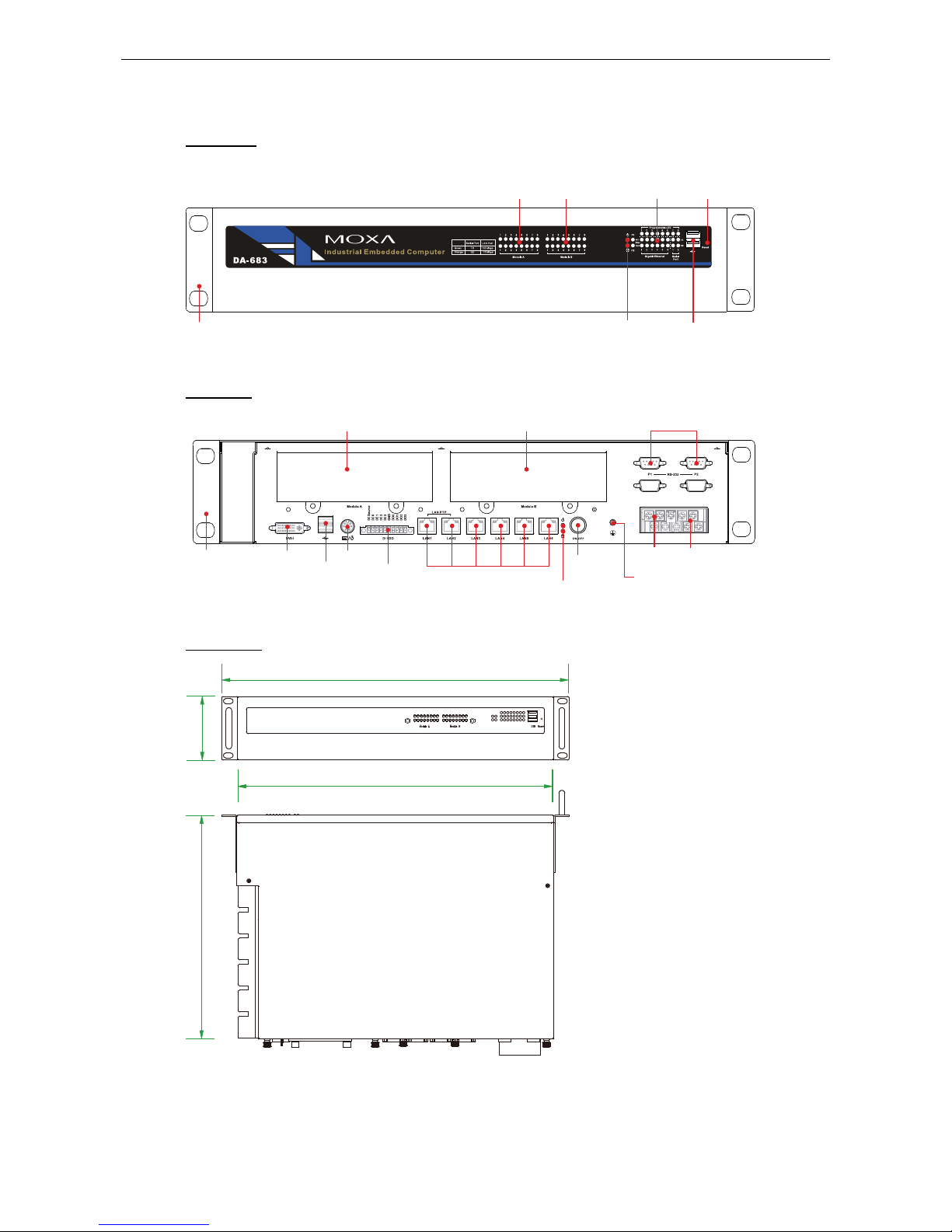
Appearance
Front View
19-inch Rackmount Ear
Module Slot B
LED x 16
(Serial/LAN)
LED (Power, Storage)
USB 2.0
Host x 2
Reset Button
Module Slot A
LED x 16
(Serial/LAN)
LED
(Programmable x 8)
(Serial, Tx x 2, Rx x 2)
(Gigabit LAN x 12)
Rear View
19-inch
Rackmount Ear
10/100/1000 Mbps
Ethernet x 6
RS-232 Serial Port x 2
(DB 9 Male)
Ground
DVI-I
PS/2
USB 2.0
Host x 2
Power
Input 1
Power
Input 2
Power
Switch
DI x 4, DO x 4
(Terminal Block)
Module Slot A Module Slot B
LED (Power, Storage)
Dimensions
440 mm (17.32 in)
483 mm (19.02 in)
90 mm (3.54 in)
315 mm (14.40 in)
1-3
Page 7
DA-683 Series Introduction
Features
The DA-683 computer has the following features:
• IEC 61850-3 certified for power substation automation systems (DPP-T models only)
• Intel Dual Core Atom D510 1.66 GHz processor
• DDR2 SODIMM socket, supporting DDR2 667 up to 2 GB (max.)
• 6 10/100/1000 Mbps Ethernet ports
• 2 RS-232 serial ports
• 4 USB 2.0 ports for high speed peripherals
• 4 DIs, 4 DOs
• CompactFlash socket for storage expansion
• 2 SATA-300 connectors for hard disk drive expansion
• 2 PCI expansion slots for inserting expansion modules
• Dual power input models available
• Ready-to-run Embedded Linux, or Windows Embedded Standard 2009 platform
• -40 to 70°C wide temperature models available
ATTENTION
Refer to the “Non-standard Baudrates” section for instructions on how to calculate which baudrates are
supported.
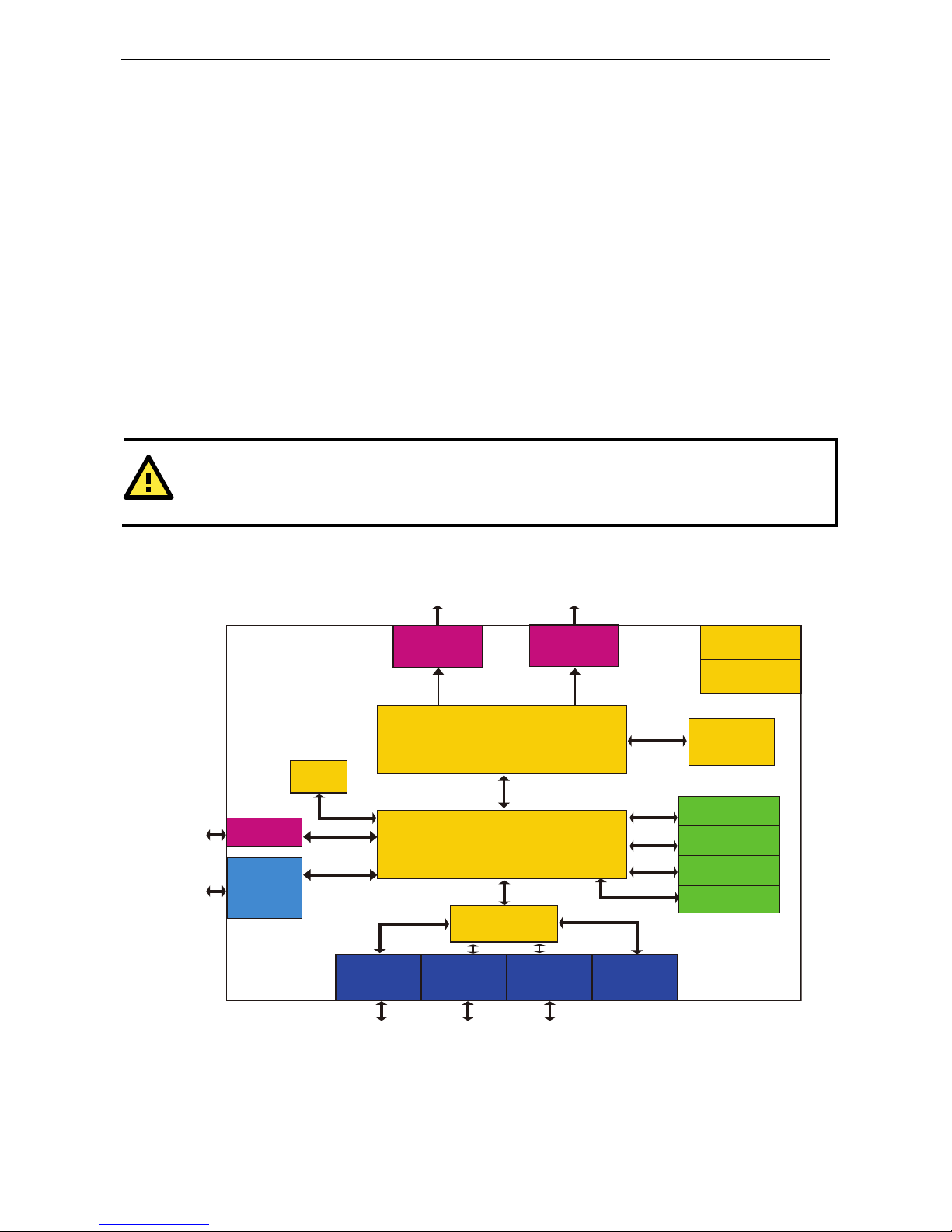
Hardware Block Diagram
Power
RTC
VGA
DDR2
SO-DIMM
Intel ICH8M
BIOS
USB 2.0 x6
Gigabit
LAN x6
Super I/O
Flash DOM
CF Socket
SATA
Intel Atom D510 Processor
DVI-I
PCI-104
PS/2
KB/Mouse
Watch Dog
Timer
DIx4
DOx4
RS-232 x 2
1-4
Page 8

DA-683 Series Introduction
Hardware Specifications
Computer
CPU: Intel Dual Core Atom D510 1.66 GHz processor
OS (pre-installed): Linux or Windows Embedded Standard 2009
System Chipset: Intel Pineview-D + ICH8M
BIOS: 16 Mbit Flash BIOS, PCI Plug & Play, ACPI function support
FSB: 667 MHz
System Memory: 1 x 200-pin DDR2 SODIMM socket supporting DDR2 667; up to 2 GB, with 1 GB built in
Expansion Bus: PCI/104 interface reserved
USB: USB 2.0 compliant hosts, Type A connector x 4, supports system boot up
Storage
Built-in: 2 GB industrial DOM onboard to store OS
Storage Expansion: CompactFlash socket for CF card expansion, supporting CF Type-I/II
HDD Support: 2 SATA-300 connectors for HDD expansion
Other Peripherals
KB/MS: 1 PS/2 interface, supports standard PS/2 keyboard and mouse through Y-type cable
Display
Graphics Controller: Intel® GMA3150 graphics controller in Intel D510 card
DVI Interface:
• Analog RBG display; output resolution up to 2048 x 1536 @ 60 Hz
• Digital DVI display; output resolution up to 1024 x 768 @ 60 Hz
Ethernet Interface
LAN: 6 auto-sensing 10/100/1000 Mbps Gigabit ports
Magnetic Isolation Protection: 1.5 KV built-in
Serial Interface
Serial Standard: 2 RS-232 ports (DB9 male)
Serial Signals
RS-232: TxD, RxD, DTR, DSR, RTS, CTS, DCD, GND, RI
Digital Input
Input Channels: 4, source type
Input Voltage: 0 to 30 VDC
Digital Input Levels for Dry Contacts:
• Logic level 0: Close to GND
• Logic level 1: Open
Digital Input Levels for Wet Contacts:
• Logic level 0: +3 V max.
• Logic level 1: +10 V to +30 V (source to DI)
Connector Type: 10-pin screw terminal block (4 DI points, 4 DO points, DI source, GND)
Isolation: 3 KV optical isolation
Digital Output
Output Channels: 4, sink type
Output Current: Max. 200 mA per channel
On-state Voltage: 24 VDC nominal, open collector to 30 V
Connector Type: 10-pin screw terminal block (4 DI points, 4 DO points, DI source, GND)
Isolation: 3 KV optical isolation
LEDs
System: Power, Storage, Power Failure x 2
Gigabit LAN: 100M x 6, 1000M x 6
Serial: TX/RX
Communication: Module A x 16, Module B x16
Programmable: LED x 8
1-5
Page 9

DA-683 Series Introduction
Switches and Buttons
Power Switch: on/off (on rear panel)
Reset Button: To reset system hardware (on front panel)
Physical Characteristics
Housing: SECC sheet metal (1 mm)
Weight: 4 kg
Dimensions: 315 x 440 x 90 mm (12.40 x 17.32 x 3.54 in) (without rackmount ears)
Mounting: Standard 19-inch rackmount
Environmental Limits
Operating Temperature:
Standard models: -10 to 60°C (14 to 140°F)
DPP-T models: -40 to 70°C (-40 to 158°F)
Storage Temperature:
Standard models: -20 to 80°C (-4 to 176°F)
DPP-T models: -40 to 85°C (-40 to 185°F)
Ambient Relative Humidity: 5 to 95% (non-condensing)
Anti-vibration: 7 mm (2-9 Hz), 20 m/s/s (9-200 Hz), 15 m/s/s (200-500 Hz) @ IEC-61850-3,
IEC 60870-2-2/Cm/(3M6)/(4M6), sine wave, 2-500 Hz, 1 Oct/min, 10 cycles, 2 hrs 40 mins per axis
Anti-shock: 300 m/s2 @ IEC-61850-3, IEC 60870-2-2/Cm/(3M6)/(4M6), half sine wave, 11 ms
Power Requirements
Input Voltage: 100 to 240 VAC, 50/60 Hz, 0.9-0.4 A
Power Consumption: 40 W
Standards and Certifications
Safety: UL/cUL (UL60950-1, CSA C22.2 No. 60950-1-03), LVD (EN60950-1), CCC (GB4943)
EMC: CE (EN55022, EN61000-3-2, EN61000-3-3, EN55024), FCC (Part 15 Subpart B, CISPR 22 Class ),
CCC (GB9254, GB 17625.1)
Green Product: RoHS, CRoHS, WEEE
Power Automation: IEC 61850-3 (DPP-T models only)
Reliability
Alert Tools: Built-in buzzer and RTC (real-time clock) with lithium backup battery
Automatic Reboot Trigger: Built-in WDT (watchdog timer) supporting 1-255 level time interval system
reset, software programmable
MTBF (meantime between failures): 134,407 hrs
Warranty
Warranty Period: 3 years
Details: See www.moxa.com/warranty
Non-standard Baudrates
Moxa’s UART ASIC, supports most non-standard baudrates in the range 50 bps to 921.6 Kbps. In fact,
supported baudrates are much denser towards the lower values. For example, no baudrates are supported
between the integers 5320 and 5323, but 49 baudrates are supported between the integers 387 and 388. Of
course this is the way it should be, since serial devices that require using non-standard baudrates generally use
slower baudrates.
Before using a serial device that requires using a non-standard baudrate, you must first check that the DA-683
supports a baudrate within the tolerance specified by the serial device manufacturer.
Use the following formula to calculate which baudrates are supported by the DA-683:
(A) Baudrate = 921600/(N+M/8) bps, for N = 1, 2, …, 18431, M = 0, 1, 2, …, 7
or
(B) Baudrate = 8 x 921600/K bps, for K = 8, 9, …, 147456
1-6
Page 10
DA-683 Series Introduction
If you are a programmer and you need to write a driver for your serial device, then you may need to use
formula A. If you have a serial device that requires using a non-standard baudrate, then you can use formula
B to determine if the DA-683 supports a baudrate within the tolerance specified by the serial device
manufacturer.
Example
: Your serial device requires using a baudrate of 5340 bps and has a tolerance of 2 bps. Can the
DA-683 be used with this device?
Solution
: Set formula B to the desired baudrate and then solve for K.
8 x 912600/K = 5338 ==> K = 1367.703259…
This shows that the supported baudrate closest to 5340 comes from setting K=1367 or K=1368.
K=1368 ==> Baudrate1 = 5336.842105...
K=1367 ==> Baudrate2 = 5340.746159…
Since 5338 – Baudrate1 < 2, we can see that the DA-683 supports the serial device.
Note that we can use formula A to generate the so-called “standard” baudrates, which come from setting M=0,
and setting N equal to certain integers.
Standard Baudrates
Baudrate N M Baudrate N M
115200 8 0 1800 512 0
57600 16 0 1200 768 0
38400 24 0 600 1536 0
19200 48 0 300 3072 0
9600 96 0 150 6144 0
7200 128 0 75 12288 0
4800 192 0 50 18432 0
2400 384 0
WARNING
Communication between a serial device and a Moxa UART port may not work correctly if the serial device uses
a baudrate that it not within the correct tolerance of a baudrate calculated from either formula A or formula B.
1-7
Page 11

2
2. Hardware Installation
The DA-683 Series of embedded computers are compact and rugged, making them suitable for industrial
applications. The LED indicators allow users to monitor performance and identify trouble spots quickly, and
multiple ports are provided for connecting a variety of different devices. The DA-683 embedded computers
come with a reliable and stable hardware platform that lets you devote the bulk of your time to application
development. This chapter describes hardware installation and connector interfaces of the DA-683 embedded
computers.
The following topics are covered in this chapter:
Placement Options
Desktop
Rack mounting
Wiring Requirements
Connecting the Power
Wiring the Power Inputs
Power Input Wiring Description
HIPOT (Dielectric Strength) Testing
Reset Button
Front Panel LED
Connecting to a Display
Connecting a PS/2 Keyboard and Mouse
Connecting USB Devices
LAN Ports
Connecting Digital Input/Output Channels
Upgrading the Memory Module
Installing a CompactFlash Card
Installing a SATA Hard Disk
Installing a PCI 104 Board
Upgrading a DOM
Inserting and Removing Expansion Modules
Page 12
DA-683 Series Hardware Installation
Placement Options
Desktop
Place your DA-683 on a clean, flat, well-ventilated desktop. For better ventilation, leave some space between
the DA-683 and other equipment. Do not place equipment or objects on top of the DA-683, as this might
damage the computer’s internal components.
Rack mounting
The DA-683 has rackmount supports for installing the embedded computer on a standard rack.
ATTENTIONS
For maximum safety, at least two persons should work together to lift, place, and attach the embedded
computer to the rack.
Before you lift or move the embedded computer, make sure that the embedded computer is turned off and the
power to the rack system is turned off.
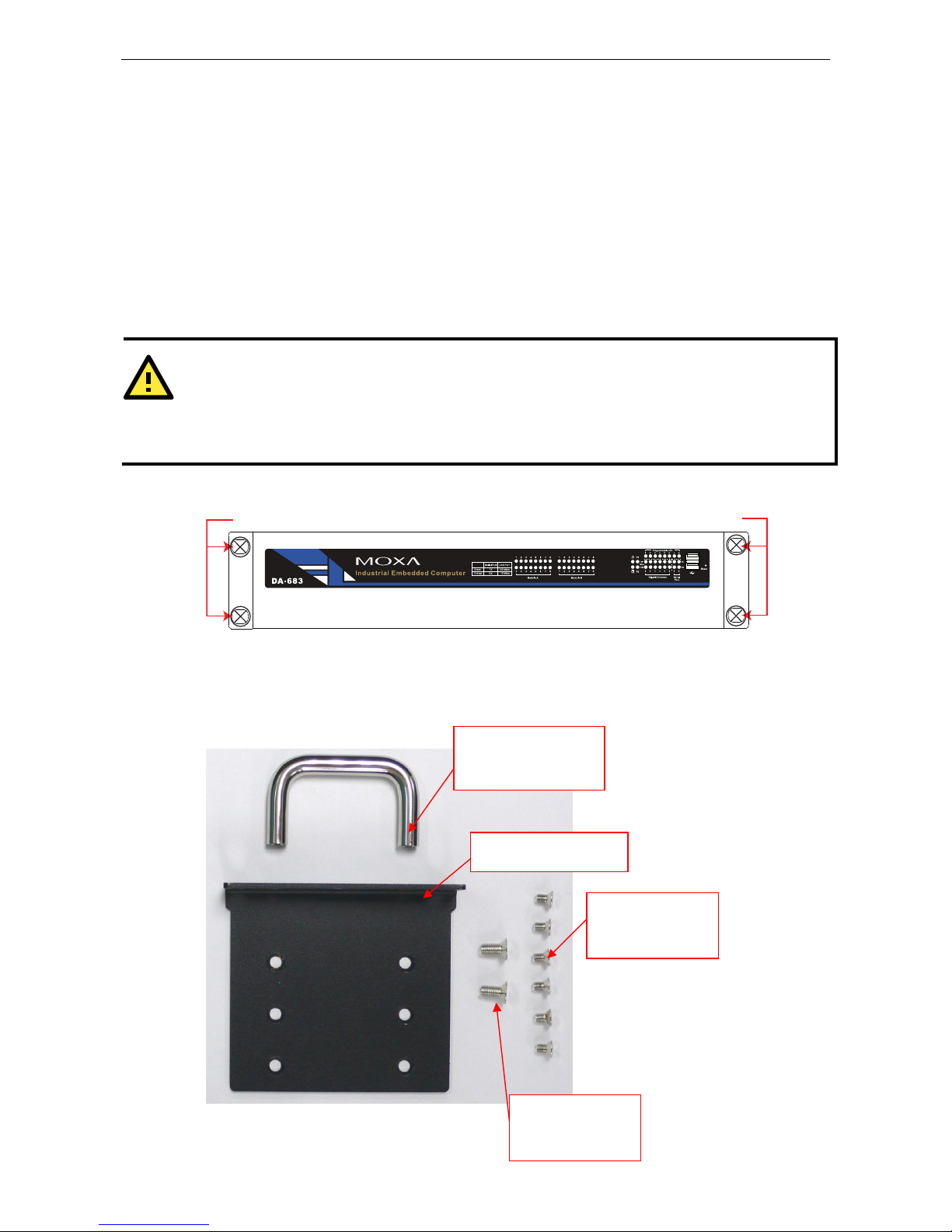
Four rackmount screws are required to attach the DA-683 to a standard rack.
Rackmount screws Rackmount screws
Follow these steps to install the DA-683 on a rack.
Step 1: Installing the rackmount supports.
Take the rackmount supports out of the packages. There are two packages, each of which contains 1
rackmount support, 1 rackmount hanger, 2 FMSM5X10 screws, and 6 FMSM4X6 screws.
Rackmount support
Rackmount hanger
FMSM4X6
screws
FMSM5X10
screws
2-2
Page 13
DA-683 Series Hardware Installation
Step 2: Installing rackmount hanger to the support.
Use 2 FMSM5X10 screws to attach the rackmount hanger to the ear. Repeat this procedure for the
additional support and hanger.
Step 3: Installing the rackmount ears to the DA-683.
Use 6 screws to attach one rackmount ear to one side of the DA-683. Repeat this procedure for the ear on
the other side of the DA-683.
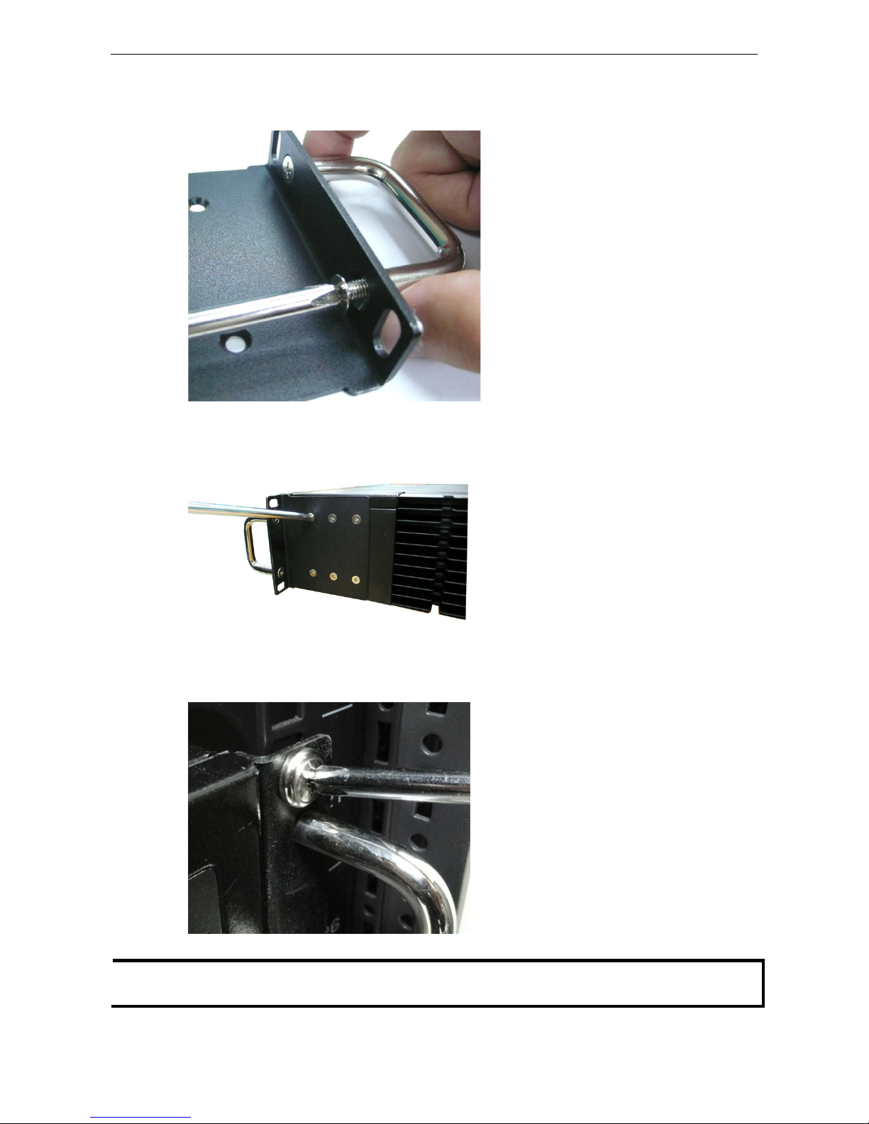
Step 4: Installing the DA-683 to a rack.
Gently slide the DA-683 onto the rack, and then use screws provided by the rack supplier to fix the
rackmount support to the rail.
NOTE That four screws are required to attach the DA-683 to the rack. Use two screws on the left side and two screws
on the right side.
2-3
Page 14
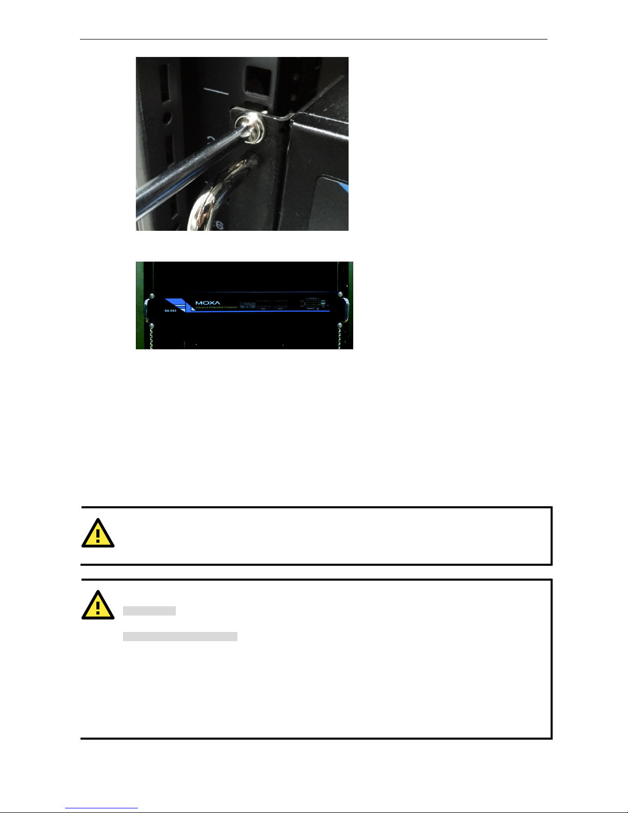
DA-683 Series Hardware Installation
As a final check, make sure that the four screws are firmly attached to the rack.
Wiring Requirements
The following common safety precautions should be observed before installing any electronic device:
• Use separate paths to route wiring for power and devices. If power wiring and device wiring paths must
cross, make sure the wires are perpendicular at the intersection point.
• You can use the type of signal transmitted through a wire to determine which wires should be kept separate.
The rule of thumb is that wiring that shares similar electrical characteristics can be bundled together.
• Keep input wiring and output wiring separate.
• When necessary, it is strongly advised that you label wiring to all devices in the system.
ATTENTION
Do not run signal or communication wiring and power wiring in the same wire conduit. To avoid interference,
wires with different signal characteristics should be routed separately.
ATTENTION
Safety First!
Be sure to disconnect the power cord before installing and/or wiring your device.
Electrical Current Caution!
Calculate the maximum possible current in each power wire and common wire. Observe all electrical codes
dictating the maximum current allowable for each wire size.
If the current goes above the maximum ratings, the wiring could overheat, causing serious damage to your
equipment.
Temperature Caution!
Be careful when handling the unit. When the unit is plugged in, the internal components generate heat, and
consequently the outer casing may feel hot to the touch.
2-4
Page 15

DA-683 Series Hardware Installation
Connecting the Power
The DA-683 offers both single power and dual power inputs. Use a screwdriver to remove the screws. Connect
the power cord to the screws and then attach the screws to the unit. For single models (SP), use Power 1 only;
for dual power models (DPP-T), use both Power 1 and Power 2 for power input installation. Refer to the
following figure for detailed information.
LED (Power, Storage)
Power
Input 1
Power
Input 2
Wiring the Power Inputs
For SP Models
PWR 1
+
L
N
NC
NC
NC NC
NC
NC
NC
Power 1
+
L
N
Chassis Ground
AC Terminal
(Green & Yellow)
Protection Earth
Line
(Black)
(White)
Bond Earth
(Green)
Neutral
Protection Earth
2-5
Page 16

DA-683 Series Hardware Installation
For DPP-T Models
AC Terminal
PWR 1 PWR 2
+
L
+
L
N
N
NC
NC
Chassis Ground
Surge Ground
Power 1
Power 2
+
L
N
+
L
N
Surge Ground
Chassis Ground
Line
(Black)
(White)
Bond Earth
(Green)
Neutral
(Green & Yellow)
Protection Earth
Protection Earth
Power Input Wiring Description
Read the following section for a detailed power input wiring description.
123456789
10
1 3 5 7 92
4 6 8 10
PWR1 PWR2
LN
LN
NC
2-6
Page 17

DA-683 Series Hardware Installation
Terminal Number Description Note
1 PWR1 Line
PWR1 Line + is connected, or to the Line terminal
for the AC power source.
2 PWR1 Neutral
PWR1 Neutral – is connected to the Neutral
terminal for the AC power source.
3 PWR1 Surge Ground
PWR1 Surge Ground is connected to the Chassis
Ground via a jumper on the terminal block. Surge
Ground is used as the ground conductor for all
surge and transient suppression circuitry. NOTE:
Surge Ground must be disconnected from Chassis
Ground during HIPOT (dielectric strength) testing.
4 Chassis Ground
Chassis Ground is connected to the Safety
Ground terminal for AC inputs, chassis ground
connects to both power supply surge grounds via a
removable jumper.
5 NC
No function
6 NC
No function
7 Chassis Ground
Chassis Ground is connected to the Safety
Ground terminal for AC inputs chassis ground
connects to both power supply surge grounds via a
removable jumper.
8 PWR2 Surge Ground
PWR2 Surge Ground is connected to the Chassis
Ground via a jumper on the terminal block. Surge
Ground is used as the ground conductor for all
surge and transient suppression circuitry. NOTE:
Surge Ground must be disconnected from Chassis
Ground during HIPOT (dielectric strength) testing.
9 PWR2 Line
PWR2 Line to the Line terminal for the AC power
source.
10 PWR2 Neutral
PWR2 Neutral is connected to the Neutral
terminal for the AC power source.
For AC Power Input
1. PWR1 Line should be connected to AC (Line).
2. PWR1 Neutral should be connected to AC (Neutral).
3. Surge Ground is connected to the Chassis Ground via a braided cable or other appropriate grounding wire.
Surge Ground is used as the ground conductor for all surge and transient suppression circuitry internal to
the protection board.
4. Chassis Ground should be connected to the AC Ground terminal.
ATTENTION
1. Equipment must be installed according to the applicable country wiring codes.
2. Surge Ground MUST be disconnected from the Chassis Ground during HIPOT (dielectric strength)
testing.
3. All line-to-ground transient energy is shunted to the Surge Ground terminal. In cases where users
require the inputs to be isolated from the ground, remove the ground braid between Surge and
Chassis Ground. Note that all line-to-ground transient protection circuitry will be disabled.
2-7
Page 18

DA-683 Series Hardware Installation
HIPOT (Dielectric Strength) Testing
Before performing the HIPOT test, you MUST have the jumpers removed and the braided ground cable
disconnected. This is required to prevent the transient/surge suppression circuitry, which is connected to Surge
Ground from being activated during the HIPOT test.
Remove Jumpers
(Green & Yellow)
Protection Earth
When finished, press the Power Switch button to start the system. It will take about 30 to 60 seconds for your
operating system to boot up.
Power Switch
Reset Button
Pressing the Reset button initiates a hardware warm reboot. The button plays the same role as a desktop PC’s
reset button. After pressing the reset button, the system will reboot automatically. During normal use, you
should NOT use the Reset Button. You should only use this button if the software is not working properly. To
protect the integrity of data being transmitted or processed, you should always reset the system from the
operating system with the software reboot function.
Reset Button
Front Panel LED
There are 60 LED indicators on the front panel. Information about each LED is given in the following table. The
additional ports LEDs, named Port 1 and Port 2 are temporarily reserved for future use.
Module Slot B
LED x 16
(Serial/LAN)
LED (Power, Storage)
LED
(Programmable x 8)
(Serial x 2)
(Gigabit LAN x 6)
Module Slot A
LED x 16
(Serial/LAN)
2-8
Page 19

DA-683 Series Hardware Installation
LED Name Color LED Description
Green Power is on Power
Off No power input or power error
Yellow /
Blinking
Data is being written to or to read from the storage unit Storage
Off Storage unit is idle
Green 1000 Mbps of Ethernet port is active Ethernet Port
1000 Mbps
Off No activity
Yellow 100 Mbps of Ethernet port is active Ethernet Port
100 Mbps
Off 10 Mbps or no activity
Green Serial port is transmitting data Serial Port TX 1-2
Off No operation
Yellow Serial port is receiving data Serial Port RX 1-2
Off No operation
Green Serial port is transmitting data, or 100 Mbps Ethernet port is active
Module Slot A
Orange Serial port is receiving data, or 10 Mbps Ethernet port is active
Green Serial port is transmitting data, or 100 Mbps Ethernet port is active
Module Slot B
Orange Serial port is receiving data, or 10 Mbps Ethernet port is active
Connecting to a Display
Your DA-683 embedded computer comes with 25-pin DVI-I female connector to connect to the DVI-I monitor.
Be sure to remove the power before you connect or disconnect the monitor cable.
18
9
16
1724
C1C2
C3C4 C5
Pin No. Signal Definition
Pin N Signal Definitioo. n
1 T.M.D.S. Data2-
16 Hot Plug Detect
2 T.M.D.S. Data2+ 17 T.M.D.S. Data0-
3 T.M.D.S. Data2/4 Shield 18 T.M.D.S. Data0+
4 N/C
19 T.M.D.S. Data0/5 Shield
5 N/C
20 N/C
6 DDC Clock
21 N/C
7 DDC Data
22 T.M.D.S. Clock Shield
8 Analog Vertical Sync
23 T.M.D.S. Clock+
9 T.M.D.S. Data1-
24 T.M.D.S. Clock-
10 T.M.D.S. Data1+
C1 Analog Red
11 T.M.D.S. Data1/3 Shield C2 Analog Green
12 N/C
C3 Analog Blue
13 N/C
C4 Analog Horizontal Sync
14 +5V Power
C5
nalog R, G, B return)
Analog Ground
(a
15 Ground (return for +5V,
HSync, and VSync)
2-9
Page 20

DA-683 Series Hardware Installation
Connecting a PS/2 Keyboard and Mouse
Your DA-683 embedded computer comes with a PS/2 mini-DIN connector to connect to a PS/2 keyboard and
PS/2 mouse by using a Y-type cable. This 6-pin mini-DIN connector has the pin assignments shown below.
PS/2
Pin No.
Signal Definition
1 PS/2 Keyboard Data
2 PS/2 Mouse Data
3 GND
4 VCC
5 PS/2 Keyboard Clock
6 PS/2 Mouse Clock
Use the Y-type cable to convert the mini-DIN connector into two 6-pin mini-DIN connectors to connect both a
PS/2 keyboard and PS/2 mouse at the same time. (The Y-type cable is not included in the accessory package.
It should be purchased separately. You may also use the USB ports to connect your USB-based keyboard and
mouse.)
ATTENTION
Please note that without the Y-type cable, the PS/2 connector on the DA-683 can only work with a PS/2
keyboard. A PS/2 mouse will not function when directly connected to the PS/2 connector on the DA-683
embedded computer.
2-10
Page 21

DA-683 Series Hardware Installation
Connecting USB Devices
The DA-683 embedded computer has four USB 2.0 ports: two are on the front panel, and two are on the rear
panel. All of the ports are UHCI, Rev 2.0 compliant and support Plug & Play and hot swapping. These ports can
be used to connect USB devices, such as a keyboard, mouse, USB flash disk, and USB CD-ROM. In addition,
both USB ports support system boot up, which can be activated by modifying the BIOS settings. The chapter
“BIOS Setup” describes the configuration process in detail.
USB 2.0
Host x 2
USB 2.0
Host x 2
LAN Ports
The DA-683 has 6 10/100/1000 Mbps LAN ports. When the cable is properly connected, the LEDs on the RJ45
connectors will glow to indicate a proper connection.
10/100/1000 Mbps
Ethernet x 6
18
Pin No.
Gigabit Ethernet Signal
1 TRD (0)+
2 TRD (0)-
3 TRD (1)+
4 TRD (2)+
5 TRD (2)-
6 TRD (1)-
7 TRD (3)+
8 TRD (3)-
LED Color Description
Green 1000 Mbps of Ethernet Port is active Ethernet Port
1000 Mbps
Off No activity
Yellow 100 Mbps of Ethernet Port is active Ethernet Port
100 Mbps
Off 10 Mbps or no activity
2-11
Page 22

DA-683 Series Hardware Installation
The default IP addresses and netmasks of the Gigabit LAN ports are as follows:
Default IP Address Netmask
LAN 1 192.168.3.127 255.255.255.0
LAN 2 192.168.4.127 255.255.255.0
LAN 3 192.168.5.127 255.255.255.0
LAN 4 192.168.6.127 255.255.255.0
LAN 5 192.168.7.127 255.255.255.0
LAN 6 192.168.8.127 255.255.255.0
NOTE Please note that the XPE models use DHCP.
Connecting Digital Input/Output Channels
The DA-683 computer comes with 4 digital input channels and 4 digital output channels located on the rear
panel. These DI/DO channels can be connected with the terminal block. See the following figures for the
locations of the DI/DO channels and the wiring methods.
DI x 4, DO x 4
(Terminal Block)
Digital Input Dry Contact Wiring Digital Input Wet Contact Wiring
Digital Output Wiring
Upgrading the Memory Module
The DA-683 embedded computer supports one 200-pin DDR2 667 SODIMM module of up to 2 GB. One DDR2
SDRAM memory module is pre-installed. To upgrade the DDR2 SDRAM memory module, follow these
instructions:
2-12
Page 23

DA-683 Series Hardware Installation
1. Disconnect the DA-683 from the power source.
2. The DA-683’s memory module is located inside the DA-683. Use a screwdriver to remove the screws on the
top cover of the DA-683.
Screws
Screws
3. After removing the cover, you will see the DDR2 SDRAM module.
Memory Socket
4. To upgrade the memory, you need to remove the original memory by pushing two clutches at both sides of
the module.
2-13
Page 24

DA-683 Series Hardware Installation
5. Gently insert the new memory into the module. Make sure the direction is correct.
6. Push the memory all the way down to complete installation.
Installing a CompactFlash Card
The DA-683 embedded computer comes with a CompactFlash socket. To insert a CompactFlash card, follow
these instructions.
1. Disconnect the DA-683 from its power source.
2. The DA-683’s CompactFlash socket is located inside the DA-683. Use a screwdriver to remove all the screws
on the top cover of the DA-683.
CompactFlash Card
Socket
2-14
Page 25

DA-683 Series Hardware Installation
3. Insert the CompactFlash card into the socket. Push downwards to make sure that the card is firmly inserted.
ATTENTION
Make sure you insert the card in the right direction. The card cannot be inserted if you insert the card in the
wrong direction.
ATTENTION
The DA-683 embedded computer does not support the CompactFlash hot swap and PnP (Plug and Play)
functions. It is necessary to remove power source first before inserting or removing the CompactFlash card.
Installing a SATA Hard Disk
The DA-683 embedded computer has one or two SATA connectors for SATA hard disks. To install a 2.5-inch
SATA hard disk, follow these instructions.
4. Disconnect the DA-683 from its power source.
5. Open the top cover of the DA-683. Refer to the following figure for the specific location for hard disk
installation..
1st HDD or PCI 104
Installation Location
Power Input 2
(DPP-T Models only)
2nd HDD Installation
Location
(SP Models only)
or
2-15
Page 26

DA-683 Series Hardware Installation
Please note that for SP models, the DA-683 allows users to install two hard disk drives inside the computer.
Users can install the hard disks at the first and second hard disk bays. For DPP-T models, users can only install
one hard disk at the first bay, as the second installation bay has been occupied by the second power input.
6. User two screws per side to attach the hard disk in the bracket. If you need to install the second hard disk,
simply attach it on the upper tier of the bracket.
Screws
7. Connect the power cable and the SATA cable to the hard disk.
SATA Cable
Power Cabble
8. You need to unscrew the cable cover on the hard disk installation bay. Open the cover and then remove the
screws on the cover.
9. Place the hard disk bracket on the computer; fasten the bracket with four screws on the corners.
2-16
Page 27

DA-683 Series Hardware Installation
10. Connect the power cable and SATA cable to the connectors on the computer.
Power ConnectorSATA Connectors
ATTENTION
The SATA hard disk cable and SATA power cable are not included in the basic shipment of the DA-683
embedded computer. Any standard SATA disk cable and power cable can be used.
Installing a PCI 104 Board
The DA-683 computer comes with one PCI 104 connector that allows users to install a PCI 104-based device.
However, this connection is located at the first hard drive installation bay. If you would like to use the PCI 104
connector, we suggest you install the hard disk at the second hard ydisk installation bau.
Follow these steps to install the PCI 104 board.
1. Fasten the four screws on the PCI 104 board bracket.
2. Connect the PCI 140 board to the connector on the computer. The connector is just located below the
bracket. When finished, fasten the two screws on the upper part of the PCI 104 board.
2-17
Page 28

DA-683 Series Hardware Installation
Upgrading a DOM
The DA-683 comes with a IDE-based DOM in which the operating system has been installed. To upgrade this
DOM, follow these step.
1. Disconnect the DA-683 from its power source.
2. Open the top cover of the DA-683. Refer to the following figure for the specific location for the DOM
installation.
DOM Location
3. Remove and pull up the DOM carefully.
4. Insert the new DOM and push downwards to finish.
DOM
Inserting and Removing Expansion Modules
The DA-683 embedded computer has two expansion slots for inserting expansion modules. Expansion modules
can b e in sta lle d in eit her on S lot A or Slo t B. To i nse rt o r re mov e ex pan sio n mo dul es, fol low the se i nstructions .
1. Disconnect the DA-683 from the power source.
2-18
Page 29

DA-683 Series Hardware Installation
2. Unscrew expansion module A or module B on the rear panel.
3. Carefully insert or remove the expansion module by pushing or pulling on the two screws at the same time.
By pushing or pulling on the two screws evenly, you can ensure that the board is inserted or removed
without being damaged.
2-19
Page 30

3
3. BIOS Setup
This chapter describes the BIOS settings of the DA-683 Computer. The BIOS is a set of input/output control
routines for peripherals. The BIOS is used to initialize basic peripherals and helps boot the operating system
before the operating system is loaded. The BIOS setup allows the user to modify the system configurations of
these basic input/output peripherals. All of the configurations will be stored in the NVRAM (Flash part), which
retains the system information after system reboots or the power is removed.
The following topics are covered in this chapter:
Entering the BIOS Setup Utility
Main Information
Modifying the BIOS Main Settings
Advanced Settings
Security Settings
Power Settings
Boot Settings
Exit Settings
Upgrading the BIOS
Page 31

DA-683 Series BIOS Setup
Entering the BIOS Setup Utility
To enter the BIOS setup utility, press the “F2” key while the system is booting up. The main BIOS Setup screen
will appear.
A basic description of each function key is listed at the bottom of the screen. Refer to these descriptions to learn
how to scroll about the screen, how to select by pressing “Enter,” and how to use the other hot keys listed
below.
F1: General Help
F5/F6: Change Values
F9: Setup Defaults
F10: Save and Exit
Main Information
The main page indicates the system information, such as model name, BIOS version, and CPU type. User may
view the basic system hardware information in the page.
3-2
Page 32

DA-683 Series BIOS Setup
Modifying the BIOS Main Settings
Advanced Settings
The “Advanced Features” screen will appear when choosing the “Advanced” item from the main menu.
Boot Configuration
This item allows users to configure the default value of Numlock.
Option: On (default), Off.
3-3
Page 33

DA-683 Series BIOS Setup
Peripheral Configuration
This item allows you to configure the parallel port and audio device.
Serial Port A
This item allows you to configure the parallel port.
Options: 378/IRQ7 (default), Disabled
Serial Port B
This item allows you to configure the parallel port.
Options: 2F8/IRQ3 (default), Disabled
Serial Port C
This item allows you to configure the parallel port.
Options: 3E8/IRQ5, Disabled (default)
Debug Port
This item allows you to configure the debug port. Please note that this port should be used only by
programmers who are familiar with debugging.
Options: 2E8/IRQ6, Disabled (default)
Parallel Port
This item allows you to configure the parallel port.
Options: 378/IRQ7 (default), Disabled
Mode
This setting allows you to configure the mode for the parallel port.
Options: SPP (default), EPP, ECP, EPP+ECP
Azalia
The item allows you to configure if the system will automatically detect the Azalia codec..
Options: Enabled (default), Disable.
3-4
Page 34

DA-683 Series BIOS Setup
IDE Configuration
This item allows you to configure the hard disk controllers.
HDC Configure As
This item allows you to configure the hard disk type.
Options: AHCI (default), PATA Only, SATA Only, IDE Non-Combined
Channel Master 1 to 3
This setting displays the storage devices installed on the Master mode in the computer. These storage devices
could be DOM, hard disk drives or a CF card.
Channel Slave 1 to 3
This setting displays the storage devices installed on the Slave mode in the computer. These storage devices
could be a DOM, hard disk drives, or a CF card.
3-5
Page 35

DA-683 Series BIOS Setup
Video Configuration
This item allows you to configure the video settings.
VGA card
This item allows you to select the onboard VGA chipset or the external VGA card installed in the PCI slot..
Options: IGD (default), PCI
IGD – Pre-Allocated
This item allows you to configure the pre-allocated capacity for the graphic memory capacity.
Options: 8 MB (default), 1 MB
IGD – DVMT Size
This item allows you to configure the capacity of the DVMT 5.0 used by the internal graphics device.
Options: 64 MB (default) , 128 MB, 224 MB
IGD – Boot Type
This item allows you to select the video device which will be activated during POST.
Options: CRT+LCD (default), CRT, LCD
IGD – LCD Panel Type
This item allows you to select the LCD panel type and the resolution.
Options: 1024x768 LVDS (default), 800x600 LVDS
3-6
Page 36

DA-683 Series BIOS Setup
USB Configuration
This item allows you to configure the USB settings.
USB Legacy
This item allows you to configure the USB devices that can be accessed during boot-up and in DOS.
Options: Enabled (default), Disabled
ACPI Table/Features Control
This item allows you to configure FACP and HPET functions.
3-7
Page 37

DA-683 Series BIOS Setup
FACP – RTC S4 Wakeup
This item allows you to enable the operating system through RTC when in sleep mode..
Options: Enabled (default), Disabled
HPET – HPET Support
This item allows you to enable/disable the HPET (High Precision Event Timer) function.
Option: Enabled (default), Disabled
Base Address Select
This item allows you to select the memory address range for the HPET.
Options: FED00000h (default), FED01000h, FED02000h, FED03000h
Hardware Monitor
This item allows you to view the status of the hardware utility. You may check various parameters for the
hardware status, such as CPU temperature, system temperature, and CPU voltage.
3-8
Page 38

DA-683 Series BIOS Setup
Security Settings
The section allows users to configure security settings with supervisor password and user password.
Set Supervisor Password
This item allows you set the supervisor password. Select and then enter the password, and then confirm the
password again.
Set User Password
This item allows you set the supervisor password. Select and then enter the password, and then confirm the
password again.
3-9
Page 39

DA-683 Series BIOS Setup
Power Settings
The section allows users to configure power settings.
Advanced CPU Control
ACPI S3
This item allows you to enable/disable Processor Performance States (P-States) function.
Options: Disabled (default), Enabled
PWRON after PWR-Fail (Power on after Power Fail)
This item allows you to configure the power on after power fail function.
Options: Off, On (default), Former-Sts
Auto Wake on S5
This item allows you to configure the wake up function on S5 status.
Options: Disabled (default)
By Every Day: You may specify the time to wake up every day.
By Day of Month: You may specify the date each month to wake up the system.
Thermal Mode
This item allows you to configure the thermal control circuit portion of the thermal monitor..
Options: TM1 (default), Disabled
3-10
Page 40

DA-683 Series BIOS Setup
HT Support
This item allows you to configure the Hyper-Threading (HT) function.
Options: Auto (default), Disabled
Use XD Capability
This item allows you to enable/disable the Intel XD function..
Options: Enable (default), Disabled
Boot Settings
The section allows users to configure boot settings.
UEFI Boot
This item allows you to enable/disable the UEFI boot function.
Options: Enabled (default), Disabled
PXE Boot to LAN
This item allows you to configure the PXE boot to LAN function.
Options: Disabled (function), enabled
USB Boot
This item allows you to enable/disable Uthe SB boot function..
Options: Enabled (default), Disabled
3-11
Page 41

DA-683 Series BIOS Setup
EFI
This item displays the boot selection for the UEFI boot function.
Legacy
Normal Boot Menu
This item allows you to configure the boot menu.
Options: Normal (default), Advance
Boot Type Order
This item allows you to select the boot order. Use F5/F6 to change values.
Options: Hard Disk Drive (default), CD/DVD-ROM Drive, USB, Others.
USB
This item allows you to view the USB device installed in the computer.
Exit Settings
The section allows users to configure exit settings.
Exit Saving Changes
This item allows you to exit and save the values you have just configured.
Options: Yes (default), No
3-12
Page 42

DA-683 Series BIOS Setup
Save Change Without Exit
This item allows you to save changes but not to exit the BIOS settings.
Options: Yes (default), No
Exit Discarding Changes
This item allows you to exit and without saving any values you have just changed.
Options: Yes (default), No
Load Defaults Setting
This item allows you to load default values for the BIOS settings
Options: Yes (default), No
Load Custom Defaults
This item allows you to load custom default values for the BIOS settings
Options: Yes (default), No
Save Custom Defaults
This item allows you to save custom default values for the BIOS settings
Options: Yes (default), No
Discard Changes
This item allows you to discard all settings you have just configured.
Options: Yes (default), No
Upgrading the BIOS
This section describes how to upgrade the BIOS. However, please note that upgrading the BIOS involves high
ris k o f d am ag e t o y our compu ter. We strongly recommend that you contact Moxa’s TS staff for assistance and
obtain all necessary tools and files before attempting to upgrade.
Step 1: Create a Bootable USB Disk.
We suggest you use the HP USB Disk Format Tool to create a bootable USB disk. You may download this tool
from the Internet. Search the Internet using the phrase “HP USB Disk Storage Format Tool”, and then
download the tool from one of the listed websites.
You will also need to download the FreeDos system files kernel.sys and command.com from
http://www.freedos.org/kernel/.
Copy DOS system files kernel.sys and command.com to a specified directory (C:\FreeDOS in this
example).
Start the HP USB Disk Storage Format Tool and select the USB device that you want to use as a bootable disk
in the Device drop down box.
Select FAT in the File system drop down box.
3-13
Page 43

DA-683 Series BIOS Setup
Type the disk name in the Volume label field.
Check the option Create a DOS startup disk under format options.
Specify the directory of the system files (for example, C:\FreeDOS).
Click Start to format and create the USB disk.
ATTENTION
We suggest you use a USB drive with under 2 GB in disk space, as larger USB drives may not support the FAT
file format and consequently fail to boot.
Step 2: Prepare the Upgrade File.
You must use the BIOS upgrade installation file to upgrade the BIOS. You can send your request to Moxa's
technical support team at support@moxa.com to get an updated version of the BIOS.
1. Get the BIOS upgrade installation file. The file name should have following format: 683xxSxx.exe (xx
refers to version numbers)
2. Copy the file to the Bootable USB Disk.
Step 3: Run the upgrade program on the DA-683 computer
1. Reboot the computer, press F12 while booting up to go to the Boot Manager
2. Select USB Disk as the first boot source. Press Enter to continue.
3-14
Page 44

DA-683 Series BIOS Setup
Boot Manager
Boot Option Menu
MOXA SSD
↑ and ↓ to change option, ENTER to select an optin, ESC to exit
Generic USB Flash Disk
3. Once the computer boots, a DOS screen will appear. Go to the directory where the upgrade file is located.
For example, if the upgrade file is stored in the DA683 folder, type cd DA683
C:\ cd DA683
4. Run the upgrade program by typing 68310S05.exe. Please note that the upgrade filename may vary
depending on the firmware version.
C:\ DA683>68310S05.exe
5. The upgrade program will run. Please wait until the procedure to be finished.
Please do not remove the AC power!
Insyde Flash Utility for InsydeH20
Version 1.4b
MOXA SSD
Initializing
Current BIOS Model name: DA-683
New BIOS Model name: DA-683
Current BIOS version: V1.00S04
New BIOS version: V1.00S05
Updating Block at FF845000
6. Once the upgrade is finished, the computer will automatically reboot. You may check the BIOS version in
Main page of the BIOS Setup
3-15
Page 45

DA-683 Series BIOS Setup
ATTENTION
Do NOT switch off the power supply during the BIOS upgrade, since doing so may cause the system to crash.
3-16
Page 46

A
A. Safety Installation Instructions
A. RTC Battery Warning
CAUTION: There is a risk of explosion if battery is replaced by an incorrect type. Dispose of used batteries
according to the instructions.
B. Fuse Warning
CAUTION: For continued protection against fire, replace only with same type and rating of fuse.
C. Rackmount Warning
The following or similar rackmount instructions are included with the installation instructions:
(1) Elevated Operating Ambient: If installed in a closed or multi-unit rack assembly, the operating ambient
temperature of the rack environment may be greater than the room ambient temperature. Therefore,
consideration should be given to installing the equipment in an environment compatible with the maximum
ambient temperature (Tma) specified by the manufacturer.
(2) Reduced Air Flow: Installation of the equipment in a rack should be such that the amount of air flow
required for safe operation of the equipment is not compromised.
(3) Mechanical Loading: Mounting of the equipment in the rack should be such that a hazardous condition is
not achieved due to uneven mechanical loading.
(4) Circuit Overloading: Consideration should be given to the connection of the equipment to the supply
circuit and the effect that overloading of the circuits might have on overcurrent protection and supply wiring.
Appropriate consideration of equipment nameplate ratings should be used when addressing this concern.
(5) Reliable Grounding: Reliable grounding of rack-mounted equipment should be maintained. Particular
attention should be given to supply connections other than direct connections to the branch circuit (e.g., by
using power strips).
D. High Temperature Warning
(1) This equipment is intended to be used in Restrict Access Location, like computer room. The access can only
be gained by SERVICE PERSONS or by USERS who have been instructed about the metal chassis of the
equipment is so hot that service persons have to pay special attention or take special protection before
touching it. Further, the access is through the use of key or security identity system. Only authorized by well
trained professional person can access the restrict access location.
(2) External metal parts are hot!! Before touching it, special attention or protection is necessary.
Page 47

B
B. Regulatory Statement Approval
This device complies with part 15 of the FCC Rules. Operation is subject to the following
two conditions: (1) This device may not cause harmful interference, and (2) this device
must accept any interference received, including interference that may cause unde
operation.
sired
Class A
: FCC Warning! This equipment has been tested and found to comp l y wit h the li m its for a Class A digital
device, pursuant to part 15 of the FCC Rules. These limits are designed to provide reasonable protection
against harmful interference when the equipment is operated in a commercial environment. This equipment
generates, uses, and can radiate radio frequency energy and, if not installed and used in accordance with the
instruction manual, may cause harmful interference to radio communications. Operation of this equipment in
a residential area is likely to cause harmful interference in which case the user will be required to correct the
interference at his own expense.
European Community
Warning:
This is a Class A product. In a domestic environment this product may cause radio interference in which case
the user may be required to take adequate measures.
 Loading...