

Moxa Technologies DA-681-I-SP-CE, DA-681-I-SP-XPE, DA-681-I-SP-LX, DA-681-I-DP-CE, DA-681-I-DP-XPE Quick Installation Manual
...
— 1 — — 2 — — 3 —
DA-681 Series Embedded
Computer
Quick Installation Guide
First Edition, January 2009
1. Overview
The DA-681 computer uses the Intel x86 processor and supports VGA,
6 Ethernet ports, 4 RS-232 and 8 RS-485 serial ports with digital
isolation, CompactFlash, and USB. The DA-681 comes in a standard
19-inch, 1U high form factor, making it an ideal platform for industrial
applications.
With its robust design, the DA-681 is suitable for industrial automation
applications that require standard 19-inch rackmount solutions, such as
power automation, transportation, and oil and gas. Another plus is that
the serial ports come with 2 KV digital isolation protection to guarantee
communication reliability in harsh industrial environments.
2. Model Names and Package Checklist
The DA-681 Series includes the following models:
y DA-681-I-SP-CE:
x86 Ready-to-Run Rackmount Computer with VGA, 6 Ethernet, 4
RS-232, 8 RS-485, CompactFlash, SATA, USB, Single Power,
WinCE 6.0
y DA-681-I-SP-XPE:
x86 Ready-to-Run Rackmount Computer with VGA, 6 Ethernet, 4
RS-232, 8 RS-485, CompactFlash, SATA, USB, Single Power,
WinXPe SP2
y DA-681-I-SP-LX:
x86 Ready-to-Run Rackmount Computer with VGA, 6 Ethernet, 4
RS-232, 8 RS-485, CompactFlash, SATA, USB, Single Power,
Linux 2.6
y DA-681-I-DP-CE:
x86 Ready-to-Run Rackmount Computer with VGA, 6 Ethernet, 4
RS-232, 8 RS-485, CompactFlash, SATA, USB, Dual Power,
WinCE 6.0
y DA-681-I-DP-XPE:
x86 Ready-to-Run Rackmount Computer with VGA, 6 Ethernet, 4
RS-232, 8 RS-485, CompactFlash, SATA, USB, Dual Power,
WinXPe SP2
y DA-681-I-DP-LX:
x86 Ready-to-Run Rackmount Computer with VGA, 6 Ethernet, 4
RS-232, 8 RS-485, CompactFlash, SATA, USB, Dual Power, Linux
2.6
Each basic system model is shipped with following standard items:
y 1 DA-681 Embedded Computer
y Quick Installation Guide
y Documentation & Software CD
y Ethernet Cable: RJ45 to RJ45 cross-over cable, 100 cm
y Product Warranty Statement
3. Hardware Installation
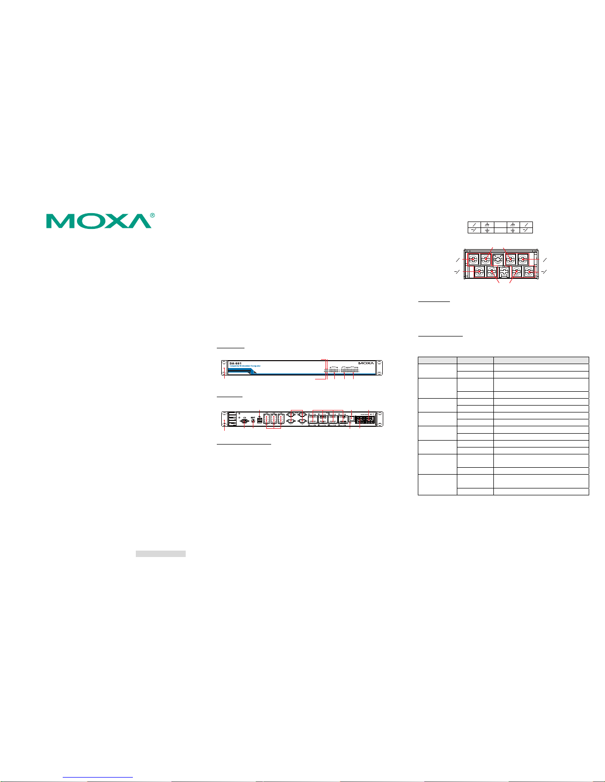
Front View
Power Fail 2
Power Fail 1
RS-232 RS-485
LED Indicators
LAN
Power
Storage
19-inch
Rackmount Ear
LED Indicators
LED Indicators
Rear View
19-inch
Rackmount Ear
10/100 Mbps Ethernet x 6
RS-232 Serial Port x 4, DB9
RS-485 Serial Port x 8,
Terminal Block
Reset Button
VGA PS/2
USB 2.0
Host x 2
Power Input 1
Power Input 2
Power Switch
Connecting the Power
DA-681 offers both single power and dual power inputs. Please use a
screwdriver to remove the screws. Connect the power cord to the
screws, and then attach the screws to the unit. For single power models,
use Power 1 only; for dual power models, use both Power 1 and Power
2 for power input installation. Refer to the following figure for detailed
information.
When finished, press the Power Switch button on the rear panel to start
the system. It will take about 30 to 60 seconds to boot up, depending on
your operating system.
PWR 1 PWR 2
+
L
+
L
N
N
NC
NC
Chasis Ground
Shielded Groud
Power 1
Power 2
+
L
N
+
L
N
Reset Button
Pressing the Reset button initiates a hardware warm reboot. The button
plays the same role as a desktop PC’s reset button. After pressing the
reset button, the system will reboot automatically.
Front Panel LEDs
There are 40 LED indicators on the front panel. Information about each
LED is given in the following table.
LED Name Color LED Description
Green Power is on
Power
Off No power input or power error
Yellow /
Blinking
Data is being written to or to read from
the storage unit
Storage
Off Storage unit is idle
Green 100 Mbps of Ethernet Port is active Ethernet Port
100 Mbps
Off No activity
Yellow 10 Mbps of Ethernet Port is active Ethernet Port
10 Mbps
Off No activity
Green Serial port is transmitting data Serial Port TX
1-12
Off No operation
Yellow Serial port is receiving data Serial Port RX
1-12
Off No operation
Red
Power 1 fails (For dual power models
only)
Power Fail 1
Off Power works well
Red
Power 2 fails (For dual power models
only)
Power Fail 2
OFF Power works well
P/N: 1802006810010
— 4 — — 5 — — 6 —
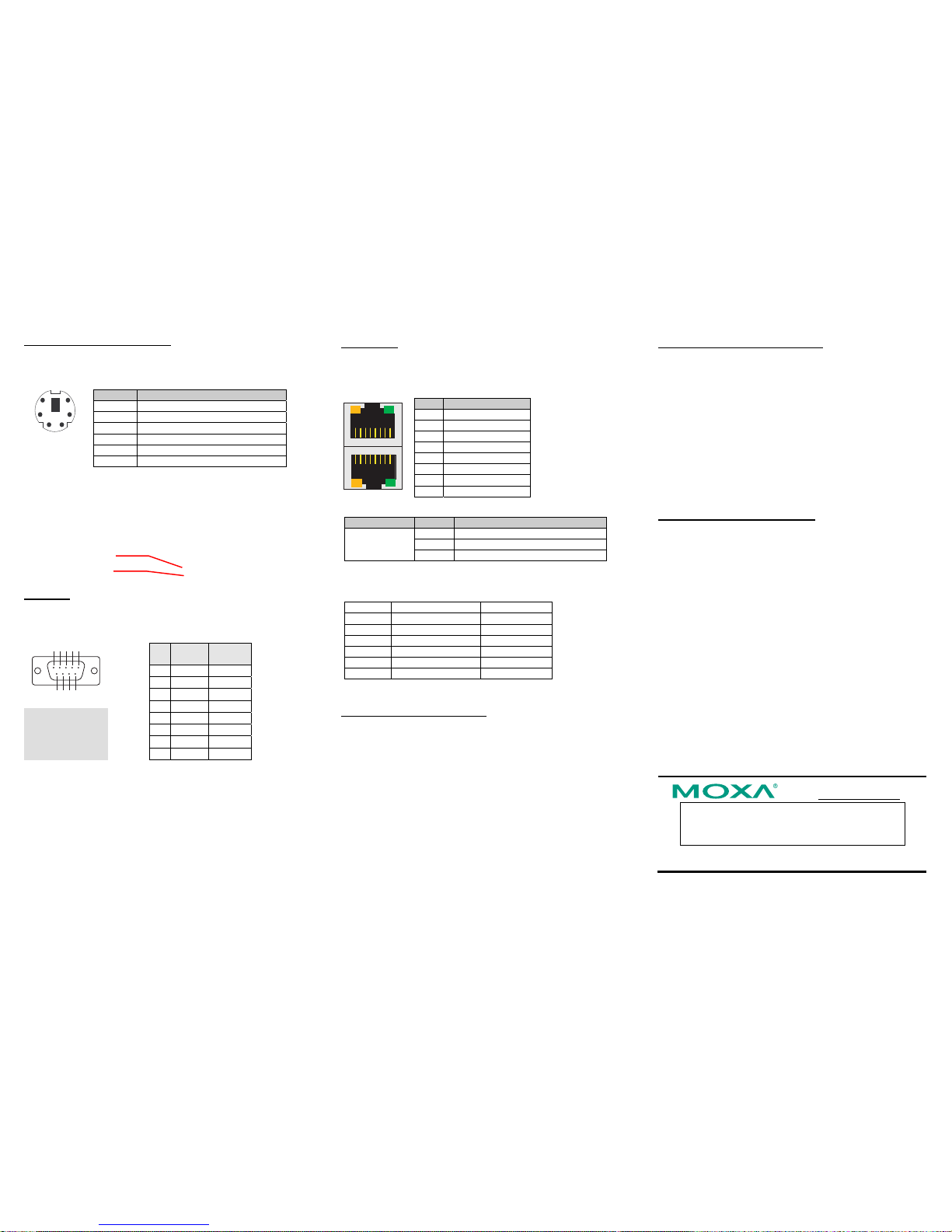
Connecting to a Keyboard and Mouse
The DA-681 comes with a PS/2 mini-DIN connector to connect a PS/2
keyboard and PS/2 mouse. This 6-pin mini-DIN connector’s pin
assignments are shown below.
12
4
6
5
3
Pin No. Signal Definition
1 PS/2 Keyboard Data
2 PS/2 Mouse Data
3 GND
4 VCC
5 PS/2 Keyboard Clock
6 PS/2 Mouse Clock
Use the Y-type cable to convert the mini-DIN connector into two 6-pin
mini-DIN connectors to connect both a PS/2 keyboard and PS/2 mouse
at the same time. (The Y-type cable is not included in the accessory
package. It should be purchased separately. You may also use the USB
ports to connect your USB-based keyboard and mouse.)
Serial Ports
The DA-681 offers six RS-232 ports with DB9 connectors and eight
RS-485 ports with Terminal Blocks. The pin assignments for the ports
are shown in the following table:
12345
6789
Pin RS-232
RS-485
(2-wire)
1 DCD --2 RxD --3 TxD Data(+)
4 DTR Data(-)
5 GND GND
6 DSR --7 RTS --8 CTS ---
Ethernet Ports
The DA-681 provides 6 10/100 Mbps Ethernet ports with RJ45
connectors. The pin assignments for the ports are shown in the
following table:
81
18
Pin No. Signal Definition
1 TX+
2 TX3 RX+
4 --5 --6 RX7 --8 ---
The LEDs on the RJ45 port indicate the following conditions:
LED Color Description
Green 100 Mbps Ethernet mode
Yellow 10 Mbps Ethernet mode
RJ45 Connector
Off No activity
The default IP addresses and netmasks of the Ethernet ports are as
follows:
Default IP Address Netmask
LAN 1
192.168.3.127 255.255.255.0
LAN 2
192.168.4.127 255.255.255.0
LAN 3
192.168.5.127 255.255.255.0
LAN 4
192.168.6.127 255.255.255.0
LAN 5
192.168.7.127 255.255.255.0
LAN 6
192.168.8.127 255.255.255.0
4. Configuring the Ethernet Interface
Linux users should follow these steps:
If you use the console cable to configure Network settings for the first
time, use the following commands to edit the interfaces file:
#ifdown –a
//Disable LAN1~LAN6 interface first, before you
reconfigure the LAN settings. LAN1 = eth0, LAN2 = eth1 and so on//
#vi /etc/network/interfaces
//check the LAN interface first//
After the boot setting of the LAN interface has been modified, use the
following commands to activate the LAN settings immediately:
#sync; ifup –a
WinCE 6.0 users should follow these steps:
Step 1: Go to Start →Settings →Network and Dial-Up
Connections. You will see two network interfaces.
Step 2: Right-click the LAN interface to be configured and click
property. A configuration window will pop-up.
Step 3: Click OK after inputting the proper IP address and netmask.
WinXPE users should follow these steps:
Step 1: Go to Start →Settings → Network Connections.
Step 2: In the screen of Local Area Connection Properties, click
Internet Protocol (TCP/IP) and then select Properties.
Step 3: Click OK after inputting the proper IP address and netmask.
NOTE: Refer to the User’s Manual for additional configuration
information.
Click here for online support:
www.moxa.com/support
The Americas: +1-714-528-6777 (toll-free: 1-888-669-2872)
Europe: +49-89-3 70 03 99-0
Asia-Pacific: +886-2-8919-1230
China: +86-21-5258-9955 (toll-free: 800-820-5036)
© 2009 Moxa Inc. All rights reserved.
Reproduction without permission is proh ibited.
PS/2 Mouse
PS/2 Keyboard
 Loading...