

Page 1

P/N: 1802006810030
*1802006810030*
DA-681A Series
Quick Installation Guide
x86 Rackmount Embedded Computers
Edition 1.0, November 2015
Technical Support Contact Information
www.moxa.com/support
Moxa Americas
:
Toll
-free: 1-888-669-2872
Tel:
1-714-528-6777
Fax:
1-714-528-6778
Moxa China (Shanghai office)
:
Toll
-free: 800-820-5036
Tel:
+86-21-5258-9955
Fax:
+86-21-5258-5505
Moxa Europe:
Tel:
+49-89-3 70 03 99-0
Fax:
+49-89-3 70 03 99-99
Moxa Asia-Pacific:
Tel:
+886-2-8919-1230
Fax:
+886-2-8919-1231
Moxa India:
Tel:
+91-80-4172-9088
Fax:
+91-80-4132-1045
2015 Moxa Inc. All rights reserved.
Page 2
- 2 -
Overview
The Moxa DA-681A Series x86-based rack-mount embedded computers
are designed for control, monitoring, data acquisition, and protocol
conversion applications. With its robust design, the DA-681A is suitable
for industrial automation applications, such as power automation,
transportation, and oil and gas.
The DA-681A’s main operating system is based on the 3rd Gen Intel®
Core™ Celeron 1047UE 1.4 GHz CPU and HM65 chipset, which supports
standard x86, 1 x VGA, 4 x USB, 6 Gigabit LAN ports, 2 RS/232/422/485
3-in-1 serial ports, and 10 RS-485 (RS-422 by CV) ports. The DA-681A
has a mini PCIe socket for mSATA and comes with Linux pre-installed;
Windows 7 Embedded is also supported by the CTOS process.
Another plus is that the serial ports come with 2 kV digital galvanic
isolation protection to guarantee commu nication reliability in harsh
industrial environments. In addition, the state-of-art IEC 61850-3, IEEE
1613, and IEC 60255 compliance all-in-one design provides rich
interfaces especially well-suited for power substation automat io n
applications.
Package Checklist
Each basic system model is shipped with following standard items:
• DA-681A rackmount computer
• Rackmount kit
• Documentation CD or DVD
• Quick installation guide (printed)
• Warranty card
Hardware Installation
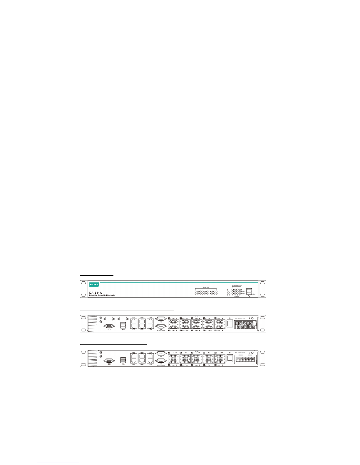
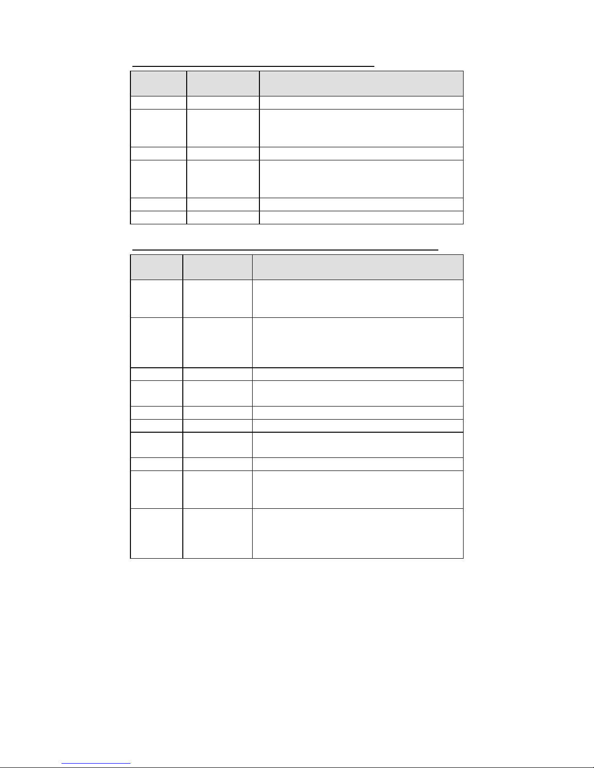
Front View
Rear View: DPP/DPP-T Models
Rear View: SP Models
Page 3

- 3 -
Connecting the Power
The DA-681A offers both single power and dual power inputs. Use a
phillips screwdriver to remove the terminal clamp screws. Connect the
power cord to the screws, and then fasten the screws to the unit. Ref er to
the following figure for detailed information.
DPP and DPP-T Models
SP Models
AC Terminal
AC Terminal
DC Terminal
DC Terminal
NOTE
1. Disconnect all power supply cords before performing
maintenance on the product.
2. Fuses (fuse F1, F2 T6.3A, 500VAC/400VDC) should be
replaced by a qualified Moxa RMA service technician.
Page 4
- 4 -
SP Model Power Terminal Block Pin Assignment
Terminal
Number
Description Note
1
N/C
No function
2
Line/DC+
Line/DC+ is connected to the positive (+)
terminal if the power source is DC, or to the
Line terminal if the power source is AC.
3
N/C
No function
4
Neutral/DC–
Neutral/DC– is connected to the negative (–)
terminal if the power source is DC, or to the
Neutral terminal if the power source is AC.
5
N/C
No function
6
N/C
No function
DPP and DPP-T Model Power Terminal Block Pin Assignment
Terminal
Number
Description Note
1 PWR1
Line/DC+
PWR1 Line/DC+ is connected to the positive
(+) terminal if the power source is DC, or to
the Line terminal if the power source is AC.
2
PWR1
Neutral/DC-
PWR1 Neutral/DC- is connected to the
negative (-) terminal if the power source is
DC, or to the Neutral terminal if the power
source is AC.
3
NC
Reserved for future customization.
4
Signal Ground
Signal Ground should be connected to the
ground terminal for AC power source 1.
5
COM
COM pin for the alarm relay.
6
NO
Normal Open pin for the alarm relay.
7
Signal Ground
Signal Ground should be connected to the
ground terminal for AC power source 1.
8
NC
Reserved for future customization.
9 PWR2
Line/DC+
PWR2 Line/DC+ is connected to the positive
(+) terminal if the power source is DC, or to
the Line terminal if the power source is AC.
10
PWR2
Neutral/DC-
PWR2 Neutral/DC- is connected to the
negative (-) terminal if the power source is
DC, or to the Neutral terminal if the power
source is AC.
When finished, press the Power Switch button on the rear panel to start
the system. It will take about 30 to 60 seconds to boot up, depending on
your operating system.
Page 5

- 5 -
Front Panel LEDs
There are 46 LED indicators on the front panel. Information about each
LED is given in the following table.
LED
Color
Description
Serial Port TX
1-12
Green
Serial port is transmitting data
Off
Not operating
Serial Port RX
1-12
Yellow
Serial port is receiving data
Off
Not operating
Power
Green
Power is on
Off
No power input or power error exists
Storage
Yellow/
Blinking
Data is being written to or read from the
storage unit
Off
Storage unit is idle
Power Fail 1
Red
Power 1 has failed
(for dual power models only)
Off
Power is being properly supplied
Power Fail 2
Red
Power 2 has failed
(for dual power models only)
Off
Power is being properly supplied
Gigabit LAN
LEDs 1-6
Green
100 Mbps Ethernet mode
Yellow
1000 Mbps (Gigabit) Ethernet mode
Off
Not operating, or in 10 Mbps Ethernet mode
Programmable
1-6
Green Defined by user
Reset Button
Pressing the Reset button initiates a warm reboot. The button plays the
same role as a desktop PC’s reset button. After pressing the reset b utton,
the system will reboot automatically. Note that all unsaved data will be
lost when you push the reset button.
Connecting to a Display
Your DA-681A embedded computer comes with a D-Sub 15-pin female
connector to connect to the VGA monitor. Be su re to remove the power
before you connect or disconnect the monitor cable.
Serial Ports
The DA-681A offers 2 RS-232/422/485 ports with DB9 connectors and 10
RS-485 ports with terminal blocks. The pin ass ignments for the po rts are
shown in the following table:
DB9 Pin Assignment
Pin
RS-232
RS-485 (4W)
RS-485 (2W)
RS-422
1
DCD
TxD-(A)
–
TxD-(A)
2
RXD
TxD+(B)
–
TxD+(B)
3
TXD
RxD+(B)
Data+(B)
RxD+(B)
4
DTR
RxD-(A)
Data-(A)
RxD-(A)
5
GND
GND
GND
GND
6
DSR – –
– 7 RTS – –
– 8 CTS – –
– 9 – – –
–
Page 6

- 6 -
Terminal Block Pin Assignment
Ethernet Ports
The DA-681A has 6 10/100/1000 Mbps LAN ports with RJ45 connectors.
The pin assignments for the ports are shown in the following table:
Pin No.
10/100 Mbps
1000 Mbps
1
TX+
TRD(0)+
2
TX-
TRD(0)-
3
RX+
TRD(1)+
4 – TRD(2)+
5 – TRD(2)-
6
RX-
TRD(1)-
7 – TRD(3)+
8 – TRD(3)-
The default IP addresses and netmasks of the Ethernet ports are as
follows:
Default IP Address
Netmask
LAN 1
192.168.3.127
255.255.255.0
LAN 2
192.168.4.127
255.255.255.0
LAN 3
192.168.5.127
255.255.255.0
LAN 4
192.168.6.127
255.255.255.0
LAN 5
192.168.7.127
255.255.255.0
LAN 6
192.168.8.127
255.255.255.0
Configuring the Ethernet Interface
Linux users should follow these steps:
If you use the console cable to configure network settings for the first
time, use the following commands to edit the interfaces file. First, take all
network interfaces offline, before you reconfigure the LAN settings:
# ifdown –a
Next, edit the network interfaces file; you may use the text editor of your
choice, but VI is the default editor on the DA-681A-LX:
#vi /etc/network/interfaces
You may set the DA-681A for either dynamic IP addressing or static
addressing. To set it for dynamic IP addressing, enter the following lines
into the network interfaces file:
# The primary network interface
auto eth0
iface eth0 inet dhcp
Page 7

- 7 -
If you wish to set an interface for static IP ad dressing, then use the
following configuration. Each interface must be configured with sepa ra te
entries in the network/interfaces file; LAN1 corresponds to eth0, LAN 2
corresponds to eth1, and so forth for the remaining interfaces.
# The loopback network interface
auto lo
iface lo inet loopback
# The first LAN interface, LAN 1
auto eth0
iface eth0 inet static
address 192.168.3.127
netmask 255.255.255.0
broadcast 192.168.3.255
# The second LAN interface, LAN 2
auto eth1
iface eth1 inet static
address 192.168.4.127
netmask 255.255.255.0
broadcast 192.168.4.255
Exit VI by typing:
:wq
After the interfaces file has been configur ed, use the following commands
to reinitialize the network interfaces and activate the new settings
immediately:
#sync; ifup –a
Win7 users should follow these steps:
Step 1:
Go to Start Control Panel Network and Internet
Network Connections.
Step 2:
From the Local Area Connection Properties screen click
Internet Protocol (TCP/IP) and then select Properties.
Step 3:
Click OK after inputting the preferred IP address a nd netmask.
 Loading...