

Moxa Technologies DA-661, DA-662, DA-663-LX, DA-661-LX, DA-662-LX Quick Installation Manual
Page 1
— 1 — — 2 — — 3 —
DA-661/662/663-LX
Quick Installation Guide
Second Edition, April 2008
1. Overview
The DA-661/662/663-LX are RISC-based, ready-to-run embedded
computers designed for industrial data acquisition applications. Each of
the three models has 16 RS-232/422/485 serial ports. In addition, the
DA-661 has two Ethernet ports, the DA-662 has 4 Ethernet ports, and
the DA-663 has 2 fiber Ethernet channels, all based on the Intel XScale
IXP-425 communication processor. The casing is a standard 1U,
19-inch wide rack-mounted rugged enclosure. The robust,
rack-mountable mechanism design provides the hardened protection
needed for industrial environment applications, and makes it easy for
users to install the DA-661/662/663 on a standard 19-inch rack. The
DA-661/662/663 are ideal for applications that require a distributed
embedded technology, such as SCADA systems, plant floor automation,
and power electricity monitoring applications.
2. Package Checklist
Before installing the DA-661/662/663-LX, verify that the package
contains the following items:
y 1 DA-661-LX, DA-662-LX, or DA-663-LX
y 19-inch Rackmount Kit
y DA-661/662/663-LX Quick Installation Guide (this guide)
y DA-661/662/663-LX Document & Software CD
y Cross-over Ethernet cable
y CBL-RJ45M9-150: 150 cm, 8-pin RJ45 to DB9 (M) serial port cable
y CBL-RJ45F9-150: 150 cm, 8-pin RJ45 to DB9 (F) console port cable
y Power Cord
y Product Warranty Statement
Notify your sales representative if any of the above items are missing
or damaged.
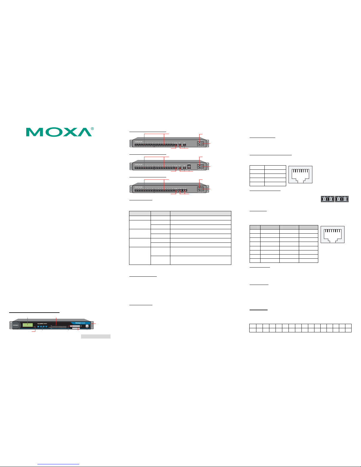
3. DA-661/662/663-LX Panel Layout
The DA-661/662/663-LX have 16 RS-232/422/485 serial ports.
Front View of DA-661/662/663-LX
LCD Screen
19-inch
Rackmount Ear
Reset Button Push Buttons
LED Indicators (Ready, LAN, Tx, Rx)
PCMCIA Socket CF Socket USB Host
USB
PCMCIA
CF
Rear View of DA-661-LX
ON/OFF Switch
10/100 Mbps Ethernet x 2 (RJ45)RS-232 Console Port
Power Input (100-240 VAC/VDC)
RS-232/422/485 Serial Ports
(RJ45, 50 to 921.6 Kbps)
Rear View of DA-662-LX
ON/OFF Switch
10/100 Mbps Ethernet x 4 (RJ45)RS-232 Console Port
RS-232/422/485 Serial Ports
(RJ45, 50 to 921.6 Kbps)
Power Input (100-240 VAC/VDC)
Rear View of DA-663-LX
ON/OFF Switch
100BaseFX x 2 (SC Connector)RS-232 Console Port
RS-232/422/485 Serial Ports
(RJ45, 50 to 921.6 Kbps)
Power Input (100-240 VAC/VDC)
LED Indicators
The following LED indicators are located on the front panel of the
DA-661/662/663-LX.
LED Name LED Color LED Function
Ready Green Power is on and functioning normally
Orange 10 Mbps Ethernet connection LAN1, LAN2,
LAN3, LAN4
Green 100 Mbps Ethernet connection
Green Serial port is transmitting data
P1-P16 (Tx)
Off Serial port is not transmitting data
Orange Serial port is receiving data
P1-P16 (Rx)
Off Serial port is not receiving data
Green
(steady on)
Fiber channel is connected
FX1, FX2
Green
(flickering)
Fiber channel is transmitting data
4. Installing Your DA-661/662/663
Desktop Mounting
Place the DA-661/662/663 on a clean, flat, well-ventilated desktop. For
better ventilation, attach the 4 pads from the desktop kit to the bottom
of the unit, and leave some space between the DA-661/662/663 and
other equipment. Do not place equipment or objects on top of the unit,
as this can cause damage to the product.
Rack Mounting
The DA-661/662/663 can be mounted on a standard 19-inch rack. Use
the enclosed pair of L-shaped metal plates and screws to fasten the
DA-661/662/663 to the rack cabinet. You can lock either the front panel
or the rear panel of the DA-661/662/663 to the front side of the rack.
Each L-shaped plate has 6 holes, leaving two outer or inner holes open
for your convenience.
5. Connecting Your
Power Connector
Connect the 100-240 VAC power line to the DA-661/662/663’s power
connector. The Ready LED on the front panel will glow a steady green
when the OS is ready.
Ethernet Ports (DA-661/662)
The 10/100 Mbps Ethernet ports (2 LAN ports for DA-661, 4 LAN
ports for DA-662) use RJ45 connectors.
Pin Signal
1 ETx+
2 ETx3 ERx+
6 ERx-
18
Fiber Ports (DA-663)
The DA-663 has 2 100BaseFX multi mode fiber
channel ports. Use multi mode optical fiber cable
(SC connector) to connect to these ports.
TX
FX 1 FX 2
RX TX RX
Serial Ports
There are 16 serial ports on the DA-661/662/663. The serial ports use
RJ45 connectors. The ports can be configured independently for
RS-232, RS-422, or RS-485 by software.
Pin RS-232 RS-422 RS-485
1 DSR --- --2 RTS TXD+ --3 GND GND GND
4 TXD TXD- --5 RXD RXD+ Data+
6 DCD RXD- Data7 CTS --- --8 DTR --- ---
18
Console Ports
The console port is an RJ45 RS-232 port. It can be connected to a V90
or GPRS modem via PPP. The pin definitions are the same as for the
serial ports.
Reset Button
Press the “Reset” button on the front panel continuously for at least 5
seconds to load the factory default configuration. After the factory
default configuration has been loaded, the system will reboot
automatically. The Ready LED will blink for the first 5 seconds, and
then maintain a steady glow once the system has rebooted.
LCD Screen
The DA-661/662/663 have an LCD screen on the front panel. The LCD
screen displays 16 columns and 2 rows of text. On boot-up, the LCD
screen displays the model name and firmware version, as shown here:
DA-661-16
VER.1.0
P/N: 1802006610011
Page 2
— 4 — — 5 — — 6 —
Push Buttons
There are four push buttons on the DA-661/662/663’s front panel. The
buttons are used to enter text onto the LCD screen. The buttons are
MENU,
(up cursor), (down cursor), and SEL:
Button Action
MENU Displays the main menu
Scrolls up through a list of items shown on the LCD
screen’s second line
Scrolls down through a list of items shown on the LCD
screen’s second line
SEL Selects the option listed on the LCD screen
Real-time Clock
The DA-661/662/663’s real-time clock is powered by a lithium battery.
We strongly recommend that you do not replace the lithium battery
without help from a qualified Moxa support engineer. If you need to
change the battery, contact the Moxa RMA service team.
ATTENTION
There is a risk of explosion if the battery is replaced by an incorrect type.
6. Powering on Your DA-661/6 62/663
To power on the DA-661/662/663, connect the power line to the
DA-661/662/663’s AC/DC power connector (located on the right side
of the rear panel) with the power cord that is shipped with the product,
and then turn on the power switch. It takes about 30 seconds for the
system to boot up. Once the system is ready, the Ready LED on the
front panel will light up, and the DA-661/662/663 will display the
model name and firmware version on the LCD screen.
7. Connecting to the DA-661/662/663 from a PC
There are two ways to connect to the DA-661/662/663 from a PC:
through the serial console port or by Telnet over the network. The
COM settings for the serial console port are: Baudrate = 115200 bps,
Parity = None, Data bits = 8, Stop bits = 1, Flow Control = None.
ATTENTION
Remember to choose the “VT100” terminal type. Use the
CBL-RJ45F9-150 cable included with the product to connect a PC to the
DA-661/662/663’s serial console port.
When using Telnet, you need to know the DA-661/662/663’s IP address
and netmask. The default LAN settings are shown below. For first-time
configuration, you may find it convenient to use a cross-over Ethernet
cable to connect directly from the PC to the DA-661/662. Please use a
Fiber-to-Ethernet converter to connect to the DA-663.
Default IP Address Netmask
LAN 1 (FX1) 192.168.3.127 255.255.255.0
LAN 2 (FX2) 192.168.4.127 255.255.255.0
LAN 3 192.168.5.127 255.255.255.0
LAN 4 192.168.6.127 255.255.255.0
Once the DA-661/662/663 is powered on, the Ready LED will light up,
and a login page will open. Use the following default Login name and
Password to proceed.
Login: root
Password: root
8. Configuring the Ethernet Interface
If you use the console cable for first-time configuration of the Network
settings, use the following commands to edit the interfaces file:
# ifdown –a
//Disable LAN1/LAN2 interface first, before you reconfigure
the LAN settings. LAN 1 = eth0, LAN 2= eth1//
# vi /etc/network/interfaces
//check the LAN interface first//
After the boot settings of the LAN interface have been modified, use
the following commands to activate the LAN settings immediately:
# sync ; ifup –a
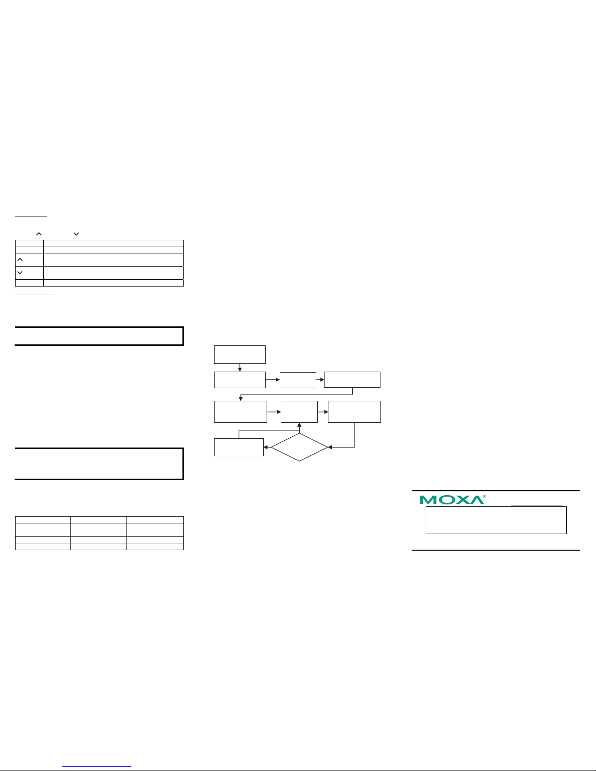
9. Developing Your Application
dna tegrat no rewoP
xuniL CP ot tcennoc
margorP
?deggubeD
ssorc UNG llatsnI
xuniL CP no relipmoc
cbilG llatsnI
xuniL CP no
CP no tneilc BDG llatsnI
)lanoitpo( xuniL
margorp edoC
elipmoC &
ot tegrat ot daolnwoD
tset dna nur
resu-dne poleveD
noitacilppa
relipmoc ssorc pu teS
tnemnorivne cbilG dna
selbairav
seY
oN
weN
margorP
10. Installing the DA-661/662/663 Tool Chain
The PC must have the Linux Operating System pre-installed to install
the DA-661/662/663 GNU Tool Chain. Redhat 7.3/8.0/9.0 Fedora Core
1/2/3/4/5 are recommended. The Tool Chain will use about 900 MB of
your PC’s hard disk space. Use the following command to install the
Tool Chain from the DA-661/662/663 CD:
# mount –t iso9660 /dev/cdrom /mnt/cdrom
# cp /mnt/cdrom/tool-chain/linux/install.sh /tmp/
# sh /tmp/install.sh
The Tool Chain will be installed on your PC automatically.
11. Compiling and Running Hello.c
The path to the Tool Chain is:
# export PATH=”/user/local/xscale_be/bin”:$PATH
The DA-661/662/663 Software CD also includes several example
programs. Here we use Hello.c as an example to show you how to
compile and run your applications. Ty pe the following commands on
your PC:
# cd /tmp/
# mkdir example
# cp –r /mnt/cdrom/example/* /tmp/example
Next, go to the Hello subdirectory and type the following command:
# make
to finish compiling Hello.c.
Finally, run the executable file that was created to generate
hello-release and hello-debug.
NOTE: Moxa also provides the Windows Tool Chain for
DA-661/662/663. The Windows Tool Chain simulates a Linux
environment on a Windows operating system, allowing you to develop
programs for DA-661/662/663 on a Windows platform. The
DA-661/662/663 User’s Manual contains complete details on how to
install the Windows Tool Chain.
12. Environmental Specifications
Power requirements 100 to 240 VAC auto ranging
(47 to 63 Hz for AC input)
Dimensions (W×D×H) 480 × 198 × 45 mm (including rack-mount ears)
440 × 198 × 45 mm (without rack-mount ears)
Operating temperature -10 to 60°C (14 to 140°F), 5 to 95% RH
Storage temperature -20 to 80°C (-4 to 176°F), 5 to 95%
Serial protection 15 KV ESD for serial port
Magnetic isolation 1.5 KV for Ethernet
Regulatory approvals FCC Class A, CE Class A, UL, CUL, TÜV
Warranty 5 years
Click here for online support:
www.moxa.com/support
The Americas: +1-714-528-6777 (toll-free: 1-888-669-2872)
Europe: +49-89-3 70 03 99-0
Asia-Pacific: +886-2-8919-1230
China: +86-21-5258-9955 (toll-free: 800-820-5036)
© 2008 Moxa Inc., All rights reserved.
Reproduction without permission is proh ibited.
 Loading...