

Page 1

CSM-200 Series
Hardware Installation Guide
First Edition, November 2009
© 2009 Moxa Inc. All rights reserved.
Reproduction without permission is prohibited.
Fl.4, No.135, Lane 235, Pao-Chiao Rd. Shing Tien City,
Taipei, Taiwan, R.O.C.
TEL: +886-2-8919-1230
P/N: 1802002002010
Page 2

Overview
Introduction
The CSM-200 series is an Ethernet to optical fiber media converter and is part
of the NRack System. It provides Ethernet media conversion from 10/100
BaseT(X) to 100 BaseFX (S C or ST connectors), and can be installed in every
chassis of the NRack System.
The CSM-200 Series includes the following models:
• CSM-200-1213: 10/100BaseT(X) to 100BaseFX slide-in module media
converter, multi-mode ST connector.
• CSM-200-1214: 10/100BaseT(X) to 100BaseFX slide-in module media
converter, multi-mode SC connector.
• CSM-200-1218: 10/100BaseT(X) to 100BaseFX slide-in module media
converter, single-mode SC connector.
Installation
The CSM-200 media converter slide-in module can be hot-swapped, which
means the chassis doesn’t need to be powered off or removed during
installation. Align the slide-in module with the chassis installation slot so that
the panel fastener screw is at the top of the module, and carefully slide the
slide-in module into the slot while aligning the module’s circuit board with the
installation guide.
Ensure that the slide-in module is firmly seated inside the chassis. Push in and
rotate the attached panel fastener screw clockwise to secure the module to the
chassis.
Why Convert Ethernet to Fiber?
Fiber communication not only extends the communication distance, but also
provides many advantageous features.
• IMMUNITY FROM ELECTRICAL INTERFERENCE:
Fiber is not affected by electromagnetic interference or radio frequency
interference. It provides a clean communication path and is immune to
cross-talk.
• INSULATION:
Optical fiber is an insulator; the glass fiber eliminates the need for using
electric currents as the communication medium.
• SECURITY:
Fiber cannot be tapped by conventional electric means and is very difficult
to tap into optically. Furthermore, radio and satellite communication
signals can be captured easily for decoding.
• RELIABILITY & MAINTENANCE:
Fiber is immune to adverse temperature and moisture conditions, does not
corrode or lose its signal, and is not affected by short circuits, power
surges, or static electricity.
- 2 -
Page 3
Features
y LFP(Link Fault Pass-through) and FEF(Far End Fault)
y Two different operation modes
¾ Store-and-Forward
¾ Pass Through
y Auto negotiation
y Support TS-1000 ver. 2
y Support Turbo Ring 2
y Plug and Play
y Hot-swap
Package Checklist
Moxa’s CSM-200 Series is shipped with the following items. If any of these
items is missing or damaged, please contact your customer service
representative for assistance.
y CSM-200 Series
y Hardware Installation Guide
y Warranty Card
NOTE: Please notify your sales representative if any of the above items are
missing or damaged.
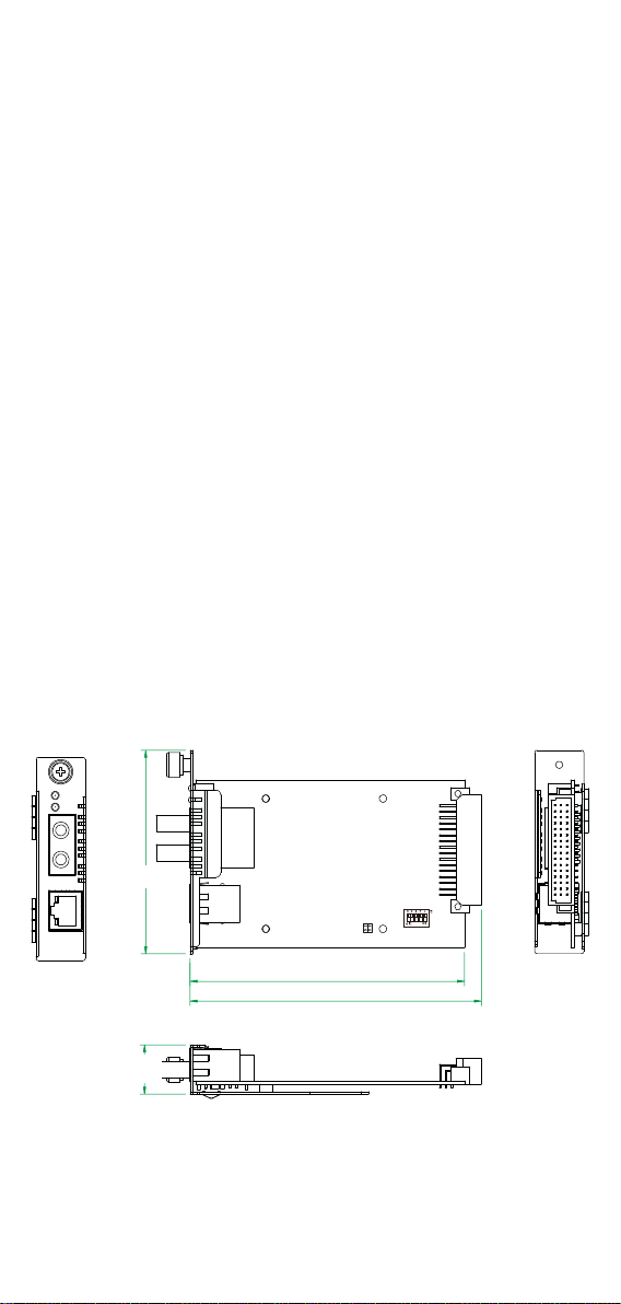
Dimensions
CSM-200-1213
PWR
Fiber
Link
TX
RX
10M
100M
86.8 mm
(3.42 in)
21 mm
(0.83 in)
117.1 mm (4.61 in)
124.3 mm (4.89 in)
- 3 -
Page 4
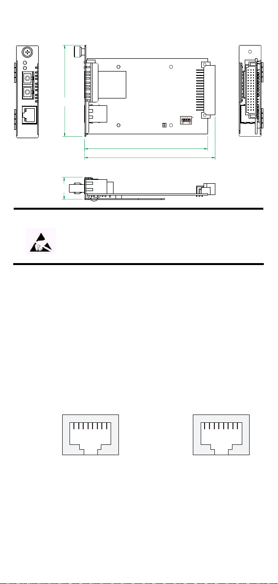
CSM-200-1214/CSM-200-1218
PWR
Fiber
Link
TX
RX
10M
100M
86.8 mm
(3.42 in)
21 mm
(0.83 in)
117.1 mm (4.61 in)
124.3 mm (4.89 in)
ATTENTION
Electrostatic Discharge Warning!
To protect the product from damage due to electrostatic
discharge, we recommend wearing a grounding device when
handling your CSM-200 slide-in modules.
Communication Connections
The CSM-200 Series has one 10/100BaseT(X) Ethernet port, and one
100BaseFX (SC or ST type connector) fiber port.
10/100BaseT(X) Ethernet Port Connection
The 10/100BaseT(X) Ethernet ports located on CSM-200 are used to connect
to Ethernet-enabled devices.
Below we show pinouts for both MDI (NIC-type) ports and MDI-X
(HUB/Switch-type) ports, and also show cable wiring diagrams for
straight-through and cross-over Ethernet cables.
RJ45 (8-pin, MDI) Port Pinouts RJ45 (8-pin, MDI-X) Port Pinouts
Pin Signal
1
Tx+
2
Tx-
3
Rx+
6
Rx-
1
8
Pin Signal
1
Rx+
2
Rx-
3
Tx+
6
Tx-
1
8
- 4 -
Page 5

RJ45 (8-pin) to RJ45 (8-pin) Straight-Through Cable Wiring
r
Switch Port
RJ45
Connector
Tx+
TxRx+
Rx-
Straight-Through Cable
RJ45 Plug Pin 1
Cable Wiring
3 3
6 6
1 1
2 2
NIC Port
RJ45
Connecto
Rx+
RxTx+
Tx-
RJ45 (8-pin) to RJ45 (8-pin) Cross-Over Cable Wiring
Switch Port
(NIC Port)
RJ45
Connector
Tx+
(Rx+)
Tx-
(Rx-)
Rx+
(Tx+)
Rx-
(Tx-)
Cross-Over Cable
RJ45 Plug Pin 1
Cable Wiring
3 1
6 2
1 3
2 6
Switch Port
(NIC Port)
RJ45
Connector
(Tx+)
Rx+
(Tx-)
Rx-
(Rx+)
Tx+
(Rx-)
Tx-
100BaseFX Fiber Port Connection
The concept behind the SC port and cable is quite straightforward. Suppose
you are connecting devices I and II. Contrary to electrical signals, optical
signals do not require a circuit in order to transmit data. Consequently, one of
the optical lines is used to transmit data from device I to device II, and the
other optical line is used transmit data from device II to device I, for
full-duplex transmission.
All you need to remember is to connect the Tx (transmit) port of device I to the
Rx (receive) port of device II, and the Rx (receive) port of device I to the Tx
(transmit) port of device II. If you are making your own cable, we suggest
labeling the two sides of the same line with the same letter (A-to-A and B-to-B,
as shown below, or A1-to-A2 and B1-to -B2).
SC-Port Pinouts SC-Port to SC-Port Cable Wiring
AA
Tx
Rx
BB
Cable Wiring
A A
B B
ST-Port Pinouts ST-Port to ST-Port Cable Wiring
AA
Tx
Rx
B
Cable Wiring
A A
B B
B
- 5 -
Page 6

ATTENTION
This is a Class 1 Laser/LED product. Do not stare into the
Laser Beam.
Switch Settings
There is 1 set of DIP switches on the board. The following figure and table
give the settings for the 5-connector DIP switch.
DIP Function ON OFF
1 Auto Negotiation Enable Disable
2 Force TP Speed 100 M 10 M
3 Force TP Duplex Full Duplex Half Duplex
4 Link Fault Pass Through Enable Disable
5 Operating Mode Store-and-Forward Pass Through
NOTE
1. A ll the DIP settings default to “ON”.
2. When configured for Pass Through mode, the Ethernet port
and fiber port should transmit at 100 Mbps, which is
equivalent to full duplex mode.
LED Indicators
There are 2 LEDs on the front bracket of the CSM-200 slide-in modules.
LED Color State Function
On Power is being supplied to power input.
PWR Green
Fiber Link Green
10M (TP) Yellow
100M (TP) Green
Off
On FX port’s 100 Mbps is active.
Blinking Data is being transmitted at 100 Mbps.
Off 100BaseFX port is inactive.
On TP port’s 10 Mbps is active.
Blinking Data is being transmitted at 10 Mbps.
Off TP port’s 10 Mbps link is inactive.
On TP port’s 100 Mbps is active.
Blinking Data is being transmitted at 100 Mbps.
Off TP Port’s 100 Mbps is inactive.
Power is not being supplied to power
input.
- 6 -
Page 7

Auto MDI/MDI-X Connection
The Auto MDI/MDI-X function allows users to connect the Moxa CSM-200’s
10/100BaseTX ports to any kind of Ethernet device, without needing to
determine the type of Ethernet cable being used for the connection.
This means that you can use either a straight-through cable or cross-over cable
to connect the CSM-200 Series to Ethernet devices.
Dual Speed Functionality and
Switching
The Moxa CSM-200’s 10/100 Mbps RJ45 Ethernet port auto negotiates with
the connected device for the fastest data transmission rate supported by both
devices. All models of the CSM-200 Series are plug-and-play devices, so that
software configuration is not required at installation, or during maintenance.
The half/full duplex mode for the RJ45 Ethernet ports is user dependent and
changes (by auto-negotiation) to full or half duplex, depending on which
transmission speed is supported by the attached device.
Auto-Negotiation and Speed Sensing
All of the CSM-200’s RJ45 Ethernet ports independently support
auto-negotiation for 10BaseT and 100BaseTX transmission speeds, with
operation according to the IEEE 802.3u standard.
This means that some nodes could be operating at 10 Mbps, while at the same
time other nodes are operating at 100 Mbps.
Auto-negotiation takes place when an RJ45 cable connection is made, and then
each time a LINK is enabled. Moxa’s CSM-200 advertises its capability for
using either 10 Mbps or 100 Mbps transmission speeds, with the device at the
other end of the cable expected to advertise similarly. Depending on what type
of device is connected, this will result in agreement to operate at a speed of
either 10 Mbps or 100 Mbps.
If a Moxa CSM-200 RJ45 Ethernet port is connected to a non-negotiating
device, it will default to 10 Mbps speed and half-duplex mode, as required by
the IEEE 802.3u standard.
- 7 -
Page 8

Specifications
Technology
Standards IEEE 802.3 for 10BaseT,
IEEE 802.3u for 100BaseT(X), 100BaseFX
Interface
RJ45 ports 10/100BaseT(X)
Fiber ports 100BaseFX (SC/ST connector)
LED Indicators PWR, Fiber Link, 10/100M(TP port)
Optical Fiber
Wavelength 1300 nm 1310 nm
Max. TX -10 dBm 0 dBm
Min. TX -20 dBm -5 dBm
RX Sensitivity -32 dBm -34 dBm
Link Budget 12 dB 29 dB
Typical Distance
Saturation -6 dBm -3 dBm
a. 50/125 μm, 800 MHz*km fiber optic cable
b. 62.5/125 μm, 500 MHz*km fiber optic cable
c. 9/125 μm, 3.5 PS/(nm*km) fiber optic cable
Physical Characteristics
Housing SPCC
Dimensions 86.8 x 124.3 x 21 mm (3.42 x 4.89 x 0.83 in)
Weight Product only:
Environmental Limits
Operating Temperature 0 to 60°C (32 to 142°F)
Storage Temperature -20 to 75°C (-4 to 158°F)
Humidity 5 to 95 % RH
Power Requirements
Input Voltage 12 VDC
Power Consumption 180 mA @ 12 VDC
Regulatory Approvals
CE Class A
FCC Part 15 sub part B class A
100BaseFX
Multi-mode Single-mode
5 km a
4 km b
40 km c
CSM-1213: 115 g (0.25 lb)
CSM-1214/1218: 125 g (0.28 lb)
Packaged:
CSM-1213: 170g (0.37 lb)
CSM-1214/1218: 180g (0.40 lb)
- 8 -
Page 9

EMS EN61000-4-2 (ESD), Criteria A, Level 4
EN61000-4-3 (RS), Criteria A, Level 2
EN61000-4-4 (EFT), Criteria A, Level 3
EN61000-4-5 (Surge), Criteria A, Level 3
EN61000-4-6 (CS), Criteria A, Level 2
En61000-4-8 (PFMF), Criteria A, Level 3
Freefall IEC 60068-2-32
Warranty
Warranty Period 5 years
Details: See www.moxa.com/warranty
Technical Support Contact Information
www.moxa.com/support
Moxa Americas:
Toll-free: 1-888-669-2872
Tel: +1-714-528-6777
Fax: +1-714-528-6778
Moxa Europe:
Tel: +49-89-3 70 03 99-0
Fax: +49-89-3 70 03 99-99
Moxa China (Shanghai office):
Toll-free: 800-820-5036
Tel: +86-21-5258-9955
Fax: +86-10-6872-3958
Moxa Asia-Pacific:
Tel: +886-2-8919-1230
Fax: +886-2-8919-1231
 Loading...