

Page 1

Universal PCI Board User’s Manual
Multiport Serial Board for PCI and PCI-X Bus
Ninth Edition, December 2012
www.moxa.com/product
© 2012 Moxa Inc. All rights reserved.
Page 2

Universal PCI Board User’s Manual
Moxa Americas
Toll
Tel:
Fax:
Moxa China (Shanghai office)
Toll
Tel:
Fax:
Moxa Europe
Tel:
Fax:
Moxa Asia
Tel:
Fax:
Moxa India
Tel:
Fax:
The software described in this manual is furnished under a license agreement and may be used only in accordance with
the terms of that agreement.
Copyright Notice
© 2012 Moxa Inc. All rights reserved.
Trademarks
The MOXA logo is a registered trademark of Moxa Inc.
All other trademarks or registered marks in this manual belong to their res pec tive manufacturers.
Disclaimer
Information in this document is subject to cha nge witho ut no tic e and doe s no t repres e nt a commitme nt o n the part of
Moxa.
Moxa provides this document as is, without warranty of any kind, either expressed or implied, including, but not limited
to, its particular purpose. Moxa reserves the rig ht to make improvements and/or changes to this manual, or to the
products and/or the programs described in this manual, a t any time .
Information provided in this manual is intended to be accurate and reliable. However, Moxa assumes no responsibility for
its use, or for any infringements on the rights of third parties that m ay res ult fr om its use.
This product might include unintentional tec hnic a l o r typographical errors. Changes are periodically made to the
information herein to correct such errors, and these changes are incorporated into new editions of the publicati o n.
Technical Support Contact Informa tion
www.moxa.com/support
-free: 1-888-669-2872
+1-714-528-6777
+1-714-528-6778
+49-89-3 70 03 99-0
+49-89-3 70 03 99-99
+91-80-4172-9088
+91-80-4132-1045
-free: 800-820-5036
+86-21-5258-9955
+86-21-5258-5505
+886-2-8919-1230
-Pacific
+886-2-8919-1231
Page 3

Table of Contents
1. Introduction ...................................................................................................................................... 1-1
Overview ........................................................................................................................................... 1-2
Applications ....................................................................................................................................... 1-4
Package Checklist ............................................................................................................................... 1-4
Product Features ................................................................................................................................ 1-5
Product Specifications ......................................................................................................................... 1-5
Installation Guide ............................................................................................................................... 1-7
2. Hardware Installation ....................................................................................................................... 2-1
Overview ........................................................................................................................................... 2-2
Configuring the Board and Dimension .................................................................................................... 2-2
CP-118U/CP-118U-I..................................................................................................................... 2-2
CP-138U/CP-138U-I..................................................................................................................... 2-3
CP-168U .................................................................................................................................... 2-5
CP-114UL/CP-114UL-I ................................................................................................................. 2-5
CP-134U/CP-134U-I..................................................................................................................... 2-7
CP-104UL ................................................................................................................................... 2-8
CP-104JU ................................................................................................................................... 2-9
POS-104UL ................................................................................................................................. 2-9
CP-112UL/CP-112UL-I ............................................................................................................... 2-10
CP-132UL/CP-132UL-I ............................................................................................................... 2-11
CP-102UL ................................................................................................................................. 2-12
CP-102U .................................................................................................................................. 2-12
CP-102UF ................................................................................................................................. 2-13
Plugging the Board into an Expansion Slot ........................................................................................... 2-14
3. Software Install at ion ........................................................................................................................ 3-1
Windows Drivers ................................................................................................................................. 3-2
Windows 7/8 (32-bit/64-bit) ......................................................................................................... 3-2
Windows 2008/Vista (32-bit/64-bit) ............................................................................................. 3-11
Windows 2003/XP ..................................................................................................................... 3-22
Windows 2000 .......................................................................................................................... 3-34
Windows NT ............................................................................................................................. 3-45
Windows 95/98/ME .................................................................................................................... 3-52
Windows CE .............................................................................................................................. 3-61
Non Windows Driver .......................................................................................................................... 3-73
DOS ........................................................................................................................................ 3-73
Linux (32-bit/64-bit) .................................................................................................................. 3-77
SCO ......................................................................................................................................... 3-77
4. Serial Programming Tools ................................................................................................................. 4-1
Overview ........................................................................................................................................... 4-2
Serial Programming Library .................................................................................................................. 4-2
PComm Utilities .................................................................................................................................. 4-2
Installation ................................................................................................................................. 4-2
PComm Diagnostic ...................................................................................................................... 4-3
PComm Monitor .......................................................................................................................... 4-3
PComm Terminal Emulator ........................................................................................................... 4-4
5. Pin Assignments ................................................................................................................................ 5-1
Overview ........................................................................................................................................... 5-2
CP-102U ............................................................................................................................................ 5-3
DB9 (Male): RS-232 .................................................................................................................... 5-3
CP-102UL .......................................................................................................................................... 5-3
DB25 (Female): RS-232 ............................................................................................................... 5-3
CP-104JU ........................................................................................................................................... 5-4
8-pin RJ45: RS-232 ..................................................................................................................... 5-4
CP-104UL .......................................................................................................................................... 5-5
DB44 (Female): RS-232 ............................................................................................................... 5-5
CP-112UL .......................................................................................................................................... 5-5
DB25 (Female): RS-232 ............................................................................................................... 5-5
DB25 (Female): RS-422 ............................................................................................................... 5-6
DB25 (Female): RS-485 (4-wire)................................................................................................... 5-6
DB25 (Female): RS-485 (2-wire)................................................................................................... 5-6
CP-114UL .......................................................................................................................................... 5-7
DB44 (Female): RS-232 ............................................................................................................... 5-7
DB44 (Female): RS-422, RS-485 (4-wire) ...................................................................................... 5-7
DB44 (Female): RS-485 (2-wire)................................................................................................... 5-8
CP-118U ............................................................................................................................................ 5-8
DB62 (Female): RS-232 ............................................................................................................... 5-9
DB62 (Female): RS-422, RS-485 (4-wire) ...................................................................................... 5-9
Page 4

DB62 (Female): RS-485 (2-wire)................................................................................................. 5-10
CP-118U-I ....................................................................................................................................... 5-11
DB78 (Female): RS-232 ............................................................................................................. 5-11
DB78 (Female): RS-422, RS-485 (4-wire) .................................................................................... 5-12
DB78 (Female): RS-485 (2-wire)................................................................................................. 5-12
CP-132UL, CP-132UL-I ...................................................................................................................... 5-13
DB25 (Female): RS-422 ............................................................................................................. 5-13
DB25 (Female): RS-485 (4-wire)................................................................................................. 5-13
DB25 (Female): RS-485 (2-wire)................................................................................................. 5-14
CP-134U, CP-134U-I ......................................................................................................................... 5-14
DB44 (Female): RS-232 (Ports 1 and 2 only) ................................................................................ 5-14
DB44 (Female): RS-422 ............................................................................................................. 5-15
DB44 (Female): RS-485 (4-wire)................................................................................................. 5-15
DB44 (Female): RS-485 (2-wire)................................................................................................. 5-16
CP-138U .......................................................................................................................................... 5-16
DB62 (Female): RS-422, RS-485 (4-wire) .................................................................................... 5-17
DB62 (Female): RS-485 (2-wire)................................................................................................. 5-17
CP-138U-I ....................................................................................................................................... 5-18
DB78 (Female): RS-422, RS-485 (4-wire) .................................................................................... 5-18
DB78 (Female): RS-485 (2-wire)................................................................................................. 5-19
CP-168U .......................................................................................................................................... 5-19
DB62 (Female): RS-232 ............................................................................................................. 5-20
POS-104UL ...................................................................................................................................... 5-20
DB44 (Female): RS-232 ............................................................................................................. 5-20
CP-102UF ........................................................................................................................................ 5-21
Serial Connectors ............................................................................................................................. 5-21
DB9 (Male) ............................................................................................................................... 5-21
DB25 (Male) ............................................................................................................................. 5-22
DB25 (Fem a l e).......................................................................................................................... 5-22
RJ45 ........................................................................................................................................ 5-23
Page 5

1
1. Introduction
The following topics are covered in this chapter:
Overview
Applications
Package Checklist
Product Features
Product Specifications
Installation Guide
Page 6

Universal PCI Board Introduction
1-2
8 Ports
CP
8 ports, RS
CP
8 ports,
CP
8 ports, RS
CP
8 ports, RS
CP
8 ports, RS
CP
8 ports, RS
CP
8 ports, RS
CP
8 ports, RS
CP
8 ports, RS
CP
8 ports, RS
4 Ports
CP
4 ports, RS
CP
4 ports, RS
CP
4 ports, RS
CP
4 ports, RS
CP
4
CP
4 ports, RS
CP
4 ports, RS
CP
4 ports, RS
CP
4 ports, RS
CP
4
CP
4 ports, RS
CP
4 ports, RS
POS
4 ports, RS
POS
4 ports, RS
2 Ports
CP
2 ports, RS
CP
2 ports, RS
CP
2 ports, RS
CP
2 ports, RS
CP
2 ports, RS
CP
2 ports, RS
CP
2 ports, RS
CP
2 ports, RS
CP
2 ports, RS
CP
2 ports, RS
CP
2 ports, RS
CP
2 ports, RS
CP
2 ports, Serial
Overview
Moxa Universal PCI (UPCI) multiport serial boards can be installed in PCI or PCI-X slots, and support both 3.3V
and 5V PCI/PCI-X. With a UPCI board, you can connect data acquisition equipment and other serial devices to
your PC over RS-232, RS-422, or RS-485. Each board has on-chip hardware and softw are f low contro l, a
built-in 128-byte Tx/Rx FIFO, and well-designed device drivers that have been fine-tuned. This allows Moxa
UPCI boards to support data transmissio n speeds of up to 921 .6 Kbps .
The following UPCI multiport serial board s ar e avai lab l e from Moxa:
-118U:
-118U-T:
-118U-I:
-118-U-I-T:
-138U:
-138-T:
-138-I:
-138-U-T-I:
-168U:
-168U-T:
-114UL:
-114UL-T:
-114UL-I:
-114UL-I-T:
-134U:
-134U-T:
-134U-I:
-134U-I-T:
-104UL:
-104UL-T:
-104JU:
-104JU-T:
-104UL:
-104UL-T:
-112UL:
-112UL-T:
-112UL-I:
-112UL-I-T:
-132UL:
-132UL-T:
-132UL-I:
-132UL-I-T:
-102UL:
-102UL-T:
-102U:
-102U-T:
-102UF:
ports, RS-422/485
ports, RS-232, low profile, wide temperature
-232/422/485
RS-232/422/485, wide temperature
-232/422/485, 2KV optical isolation
-232/422/485, 2KV optical isolation, wide temperature
-422/485
-422/485, wide temperature
-422/485, 2KV optical isolation, wide temperature
-422/485, 2KV optical isolation
-232
-232, wide temperature
-232/422/485, low profile
-232/422/485, low profile, wide temperature
-232/422/485, low profile, 2KV optical isolation
-232/422/485, low profile, , 2KV optical isolation, w ide temperature
-422/485, wide temperature
-422/485, 2KV optical isolation
-422/485, 2KV optical isolation, wide temperature
-232, low profile
-232, 8-pin RJ45 connector on-board
-232, 8-pin RJ45 connector on-board, wide temperature
-232, low profile, serial port powered
-232, low profile, serial port powered, wide temperature
-232/422/485, low profile
-232/422/485, low profile, wide temperature
-232/422/485, low profile, 2KV optical isolation
-232/422/485, low profile, 2KV optical isolation
-422/485, low profile
-422/485, low profile, wide temperature
-422/485, low profile, 2KV optical isolation
-422/485, low profile, 2KV optical isolation, wide temperature
-232, low profile
-232, low profile, wide temperature
-232
-232, wide temperature
-over-fiber board
Page 7

Universal PCI Board Introduction
1-3
Smartio—The Smart Multiport Async Solution
The Smartio Series of multip or t s eri al bo ard s includ e s the CP-168U, CP-104UL, CP-104JU, POS-104UL,
CP-102UL, and CP-102U. These boards provide RS-232 serial ports for connecting terminals, modems, printers,
scanners, cash registers, bar code readers, keypads, numeric displays, electrical scales, data acquisition
equipment, and many other serial devices to a PC. These boards are a reliable, high-performance solution for
multiport serial communication.
Industio—The Industrial Multiport Async Solution
The Industio Series of multiport s er ial bo ard s includes the CP-118U-I, CP-118U, CP-138U-I, CP-138U,
CP-114UL, CP134U, CP-134U-I, CP-132UL, and CP-132UL-I. These boards are designed for industrial use, with
serial ports that can be configured independently for RS-232, RS-422, or RS-485 operation. Industio boards
provide a reliable communication link over distances of up to 4000 ft and support point-to-point full-duplex or
multi-drop half-duplex. With RS-485 operation, a single port can connec t to 32 devices in a multi-drop
environment.
ADDCTM (Automatic Data Direction Control) for RS-485
ADDC™ (Automatic Data Direction Control) makes it easier to manage 2-wire RS-485 half-duplex connections,
eliminating the need for software interf er e nc e . This mea ns that it is not neces s ary to write ex tra code for
Windows applications to control the hal f -duplex protocol. ADDC intelligence is built into Industio boards.
Serial-over-fiber Board
The CP-102UF is a serial-over-fiber board designed for industrial auto mation applications that require a long
distance, multi-point, PC-based data acquisitio n solution. The single-mode model (CP-102UF-S) can transmit
up to 40 km, and the multi-mode model (CP-102UF-M) can transmit up to 5 km. For many industrial
applications, an even bigger benefit is that optical fiber iso lates the da ta from dangerous increases in ground
potential, ground loops, and electri c al EMI/RFI electromagnetic radiation.
Built-in Termination Resistors for RS-422 and RS-485
Industio boards have termination resistors built-in, eliminating the headaches involved in determining the
proper impedance for the resistors. For additional information, ple a se refer to Cha p ter 2.
ESD and Isolation Protection
Certain models include TVSS (Transient Voltage Surge Suppressor) technology to help prevent damage due to
lightning or high potential voltage. Optic al is olation (2000V) and embedded protection (max. ESD of 16 KV,
max. EFT of 2 KV) are also available with certain models. These features help provide protection in critical or
harsh factory-type environments.
PCI Solution
UPCI boards comply with PCI Spec. 2.1 and do not require switches or jumpers. IRQ and I/O address is
automatically assigned by the PCI BIOS. This means that the board must be physically installed in the computer
first before the driver software is install e d .
Page 8

Universal PCI Board Introduction
1-4
Universal PCI
For maximum compatibility with the PCI local bus spe c ific ati o n, U PCI board s suppo rt both 3.3V and 5V PCI
connector types. The 32/64-bit PCI local bus specification specifies both a 3.3V/5V and 32/64-bit slot.
Operating System Support
Moxa UPCI boards are compatible w ith mos t major ind us trial platforms, including Windows, DOS, and Linux .
Drivers are provided for smoother installation, configuration, and performance. This manual provides separate
sections for the different operating systems that are supported.
Moxa Serial Communication Tools
For application development, Moxa provides a serial communication library for Windows called PComm. This
library can help you develop your own applications in Visual Basic, Vi s ual C++, Bor l and Delphi, a nd more.
Utilities are included for debugging, monitor ing communic a tio n s tatus , te rminal emulation, and file transfer.
Applications
UPCI boards are suita b le for many ind us trial applications, including the following:
• Multipoint data acquisition
• Factory automation
• Critical industrial control
• Remote serial device control
• Internet/intranet connecti o ns
• Remote access applications
• Multi-user applications
• Industrial automation
• Office automation
• Telecommunications
• PC-based vending machines or kiosk systems
• POS (Point-of-Sale) systems
Package Checklist
UPCI boards are shipp ed with the following items:
• 1 Moxa UPCI multiport serial board
• Low profile bracket (low profile models only)
• Document & Software CD
• Quick Installation Guide
• 5-year Product Warranty statement
NOTE: Notify your sales representative if any of the abov e items is missing or damaged. For info rma tio n on
optional accessories for each model, pl ease refer to Chapter 5.
Page 9

Universal PCI Board Introduction
1-5
Hardware
I/O Controller:
MU860 (compatible with 16C550C)
Connector Type:
CP
Female DB78
CP
Female DB62
CP
Female DB78
CP-138U:
Female DB62
CP
Female DB62
CP
F
CP
Female DB44
CP
Female DB44
CP
8
POS
Female DB44
CP
Female DB25
CP
Female DB25
CP
Female DB25
CP-102U:
Male DB9
CP
Female DB44
CP
Female DB44
CP
Female DB44
CP
Female DB25
CP-132UL-I :
Female DB25
CP
ST type
Product Features
Moxa UPCI boards enjoy the following features:
• Over 700 Kbps data throughput for top performance
• Serial communication speed up to 921 . 6 Kbps
• 128-byte FIFO and on-chip hardw are and softw are flow co ntro l
• Universal PCI supporting 3.3V PCI, 5V PCI and PCI-X
• Driver support for Windows, Windows CE, Windows XP Embedde d , DOS, Linux, Fr e eBSD, QNX SCO
OpenServer, UnixWare7
• On-board 15 KV ESD protection
• Low profile for compact-sized PCs (on “L” models only)
• 2 KV optical isolation protection (on “I” models only )
• -40 to 85°C wide temperature (on “T” models only)
Product Specifications
-118U-I:
-118U:
-138U-I:
-168U :
-114UL/CP-114UL-I:
-134U/CP-134U-I :
-104UL :
-104JU :
-104UL:
-112UL/CP-112UL-I:
-132UL/CP-112UL-I:
-102UL:
-114UL:
-134U :
-134U-I :
-132UL :
-102UF:
emale DB44
-pin RJ45
Page 10

Universal PCI Board Introduction
1-6
Interface
Bus: 32
No. of Ports:
8 Ports:
CP
CP
CP
4 Ports:
CP
CP
CP
POS
2 Ports:
C
CP
CP
CP
Max. No. of Boards:
4 Signals
RS
TxD, RxD, RTS, CTS, DTR, DSR, DCD, GND
RS
TxD+(B), TxD
4
TxD+(B), TxD
2
Data+(B),
Performance
Baudrate:
50 bps to 921.6 Kbps
Configuration
Parity:
None, Even, Odd, Space, Mark
Data Bits:
5, 6, 7, 8
Stop Bits:
1, 1.5, 2
I/O Address, IRQ:
Assigned by BIOS
FIFO:
128 bytes
Flow Control:
RTS/CTS, XON/XOFF
Driver
Windows 2012 x64, 8 x86/x64
Windows 7 x86/x64
Windows 2000
Windows XP/2003/Vista/2008 (x86
Linux 2.4
Linux 2.6 (x86
Complete driver support information is available at
Download center
Power Output:
5V/12V (POS
Power and Environment
Operating Temperature:
0 to 55°C (32 to 131°F)
Operating Humidity:
5 to 95% RH
Storage Temperature:
-
Protection:
Embedded 15 KV ESD protection
Certifications
Approved:
EN55022 Class B, EN55 024, EN61000
IEC61000
IEC61000
Warranty
5 years
-232:
-422:
-wire RS-485:
-wire RS-485:
Support:
-bit Universal PCI
-118U/CP-118U-I
-138U/CP-138U-I
-1168U
-114UL/CP-114UL-I
-134U/CP-134U-I
-104UL/CP-104JU
-104UL:
P-112UL/CP-112UL-I
-132UL/CP-132UL-I
-102UL
-102U/CP-102UF
-(A), RxD+(B), RxD-(A), GND
-(A), RxD+(B), RxD-(A), GND
Data-(A), GND
/x64)
/x64)
www.moxa.com in the
.
-104UL only)
40 to 85°C (-40 to 185°F)
-3-2, EN61000-3-3, IEC61000-4-2,
-4-3, IEC61000-4-4, IEC61000-4-5, IEC61000-4-6, IEC61000-4-8,
-4-11, FCC Part 15 Class B
Page 11

Universal PCI Board Introduction
1-7
Step 1:
Select serial transmission mode
For certain models, you will need to set onboard DIP switches to s
transmission mode
for each port.
CP
104UL, and
CP
Step 2:
Install board
UPCI
ls, please refer
to
Step 3:
Install drivers and configure boar d
For details, please refer to
Step 4:
Connect
For details, please refer to
Step 5:
Restart system and
For details, please refer to
Step 6:
Develop and run your serial communication applica tio n
For details, please refer to
Installation Guide
UPCI board installation can be divided into s ix s teps as follows :
This applies to the CP-118U-I, CP-138U-I, CP -118U, CP-138U, CP-114UL,
-114UL-I, CP-134U, CP-134U-I, CP-112UL, CP -112UL-I, CP-132UL, CP-132UL-I, POS-
-102UF. For details, please refer to Chapter 2.
Chapter 2.
.
boards are installed in an open PCI or PCI-X expansion slot on the PC. For detai
your serial devices to the board’s serial po rts
verify dr iver initialization
.
elect the serial
Chapters 3 through 8.
Chapter 10.
Chapters 3 through 8.
Chapter 9.
Page 12

2
2. Hardware Installation
The following topics are covered in this chapter:
Overview
Configuring the Board and Dimension
CP-118U/CP-118U-I
CP-138U/CP-138U-I
CP-168U
CP-114UL/CP-114UL-I
CP-134U/CP-134U-I
CP-104UL
CP-104JU
POS-104UL
CP-112UL/CP-112UL-I
CP-132UL/CP-132UL-I
CP-102UL
CP-102U
CP-102UF
Plugging the Board into an Expansio n Slo t
Page 13
Universal PCI Board Hardware Installation
2-2
Overview
This chapter explains the hardwar e installati o n p rocedure in detail. Since the BIOS automatically assigns the
IRQ number and I/O addresses, you will need to install the board before you install the drivers. You can install
up to 4 UPCI boards in one system, as long as sufficient I/O address and IRQ number resources are available.
Configuring the Board and Dimension
8 Ports
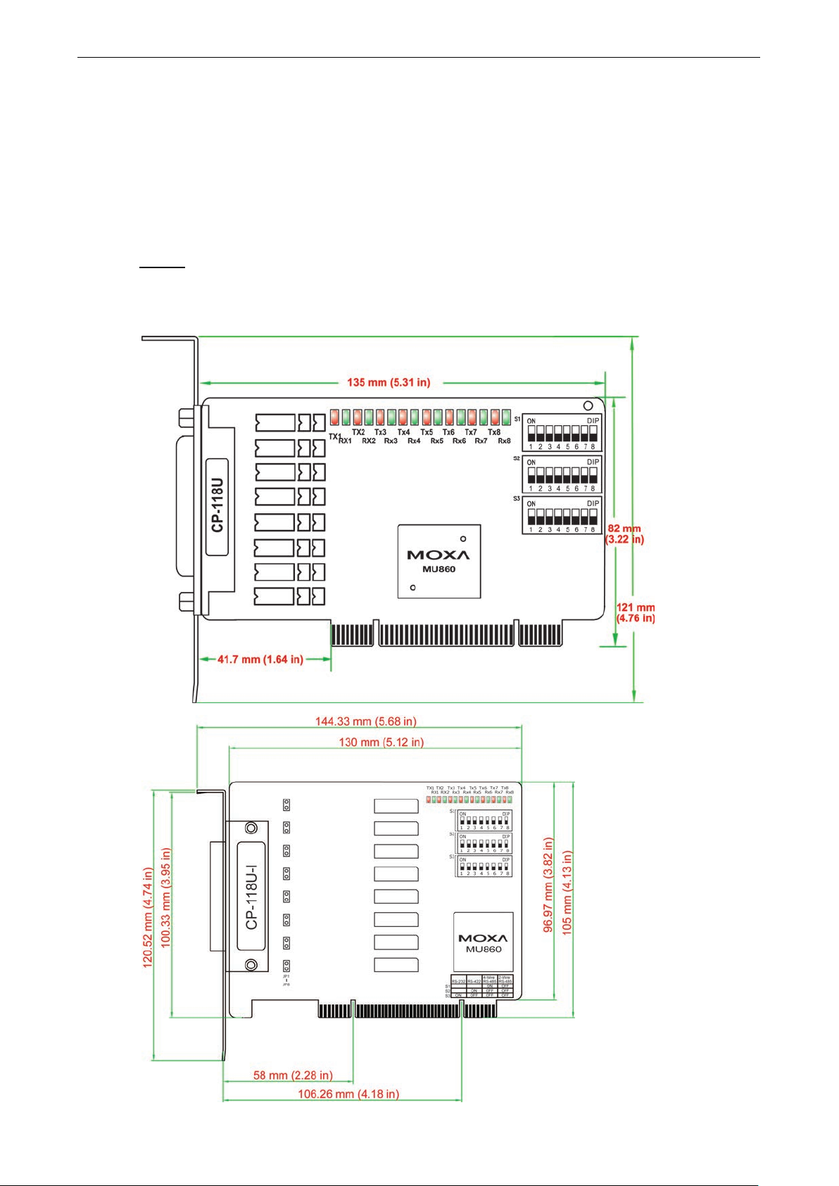
CP-118U/CP-118U-I
Page 14
Universal PCI Board Hardware Installation
2-3
Onboard termination resistors can be activated individually for each serial port using jumpers JP1 through JP8.
For CP-118U-I, JP1/2/3/4/5/6/7/8 corresponds to serial por t 1/2/3/4/5/6/7/8, respectively. For C P-118U,
JP1/2/3/4/5/ 6/7/ 8 co rresp onds to se rial port 8/ 7/6/ 5/4/ 3/2/ 1, respectively. Short the jumper pins to activate
the termination resistor; leave the jumper pins op e n to bypass the term ination resistor.
The onboard DIP switches, S1, S2, and S3, a re used t o select RS-232, RS-422, or RS-485 mode for each serial
port. There are 8 switches on each bank corresponding to the 8 serial ports. S3 selects between RS-232 and
RS-422/485, S2 selects between RS-422 and RS-485, an d S1 selects between 2-wire and 4-wire RS-485, as
follows:
Mode S1 S2 S3
RS-232 --- --- ON
RS-422 --- ON OFF
4-wire RS-485 ON OFF OFF
2-wire RS-485 OFF OFF OFF
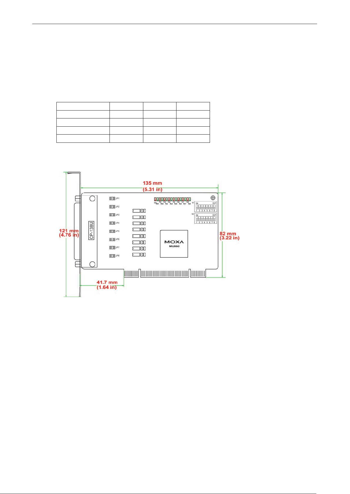
CP-138U/CP-138U-I
Page 15

Universal PCI Board Hardware Installation
2-4
Onboard termination resistors can be activated individually for each serial port using jumpers JP1 through JP8.
For CP-138U-I, JP1/2/3/4/5/6/7/8 corr espo nd s to serial po rt 1/2/3/4/5/6/7/8, respectively. For CP-138U,
JP1/2/3/4/5/6/7/8 corresponds t o seri al po rt 8/7/ 6/5/ 4/3/ 2/1, respectively. Short the jumper pins to activate
the termination resistor; leave the jumper pins op e n to bypass the ter minati o n re s is tor .
The on board DIP switches, S1 and S2, are used to select RS-422 or RS-485 mode for each serial port. There are
8 switches on each bank corresponding to the 8 serial ports. S2 selects between RS-422 and RS-485; S1
selects between 2-wire and 4-wire RS-485, as follows:
Mode S1 S2
RS-422 --- ON
4-wire RS-485 ON OFF
2-wire RS-485 OFF OFF
Page 16
Universal PCI Board Hardware Installation
2-5
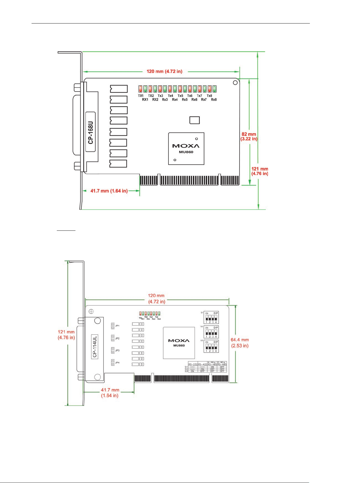
CP-168U
This board does not require configuration.
4 Ports
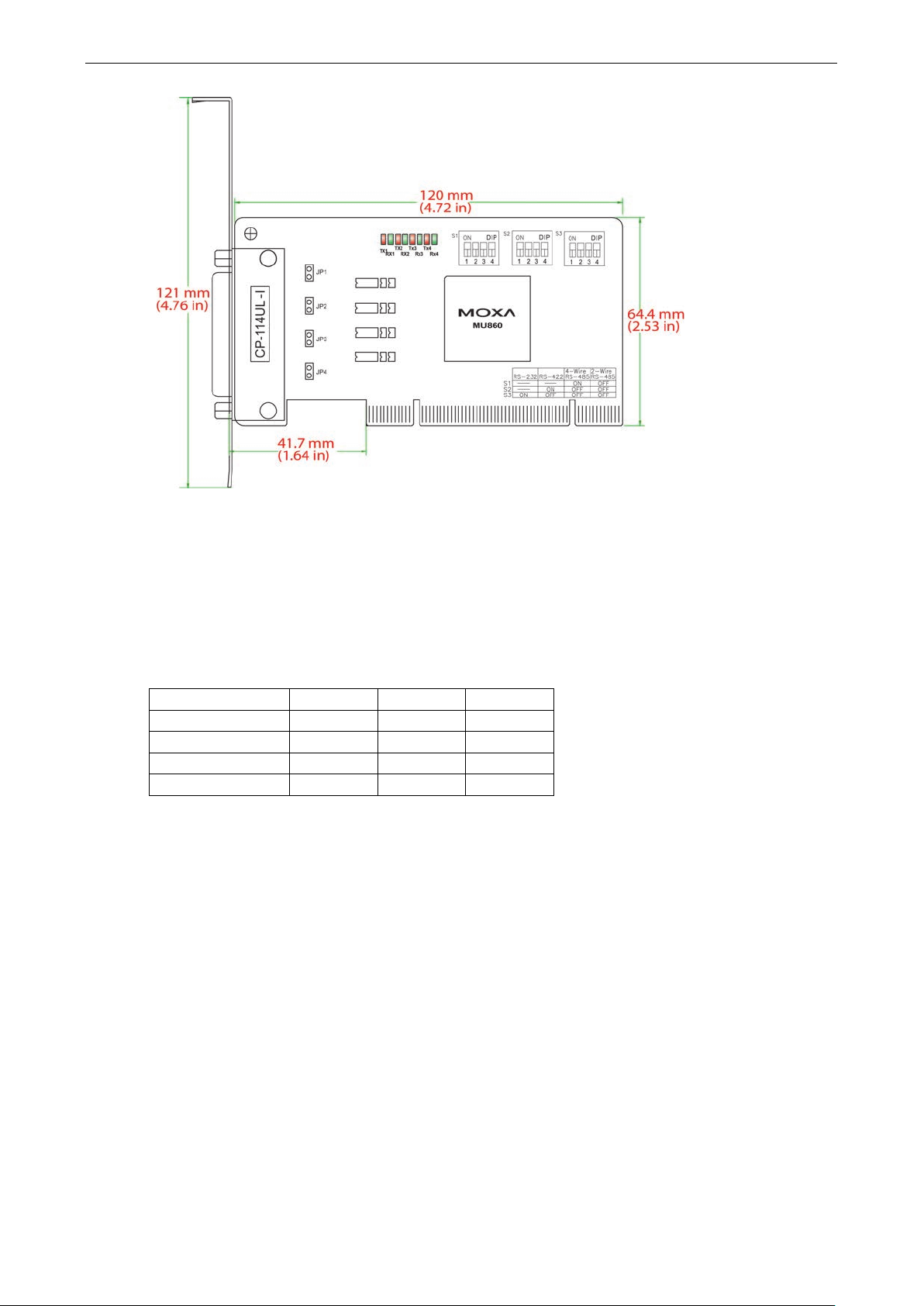
CP-114UL/CP-114UL-I
Page 17
Universal PCI Board Hardware Installation
2-6
Onboard termination resistors can be activated individually for each serial port using jumpers JP1 through JP4.
For CP-114UL, JP1/2/3/4 corresponds to serial port 1/2/3/4, respectively. For CP-114UL-I, JP1/2/3/4
corresponds to serial port 4/3/2/1, respectively. Short the jumper pins to activate the termination resis tor ;
leave the jumper pins open to bypass the termination res is tor.
The onboard DIP switches, S1, S2, and S3, a re used t o select RS-232, RS-422, or RS-485 mode for each serial
port. Switches 1 through 4 on each bank correspond to the 4 serial ports . S3 selects between RS-232 and
RS-422/485, S2 selects between RS-422 and RS-485, an d S1 selects between 2-wire and 4-wire RS-485, as
follows:
Mode S1 S2 S3
RS-232 --- --- ON
RS-422 --- ON OFF
4-wire RS-485 ON OFF OFF
2-wire RS-485 OFF OFF OFF
Page 18
Universal PCI Board Hardware Installation
2-7
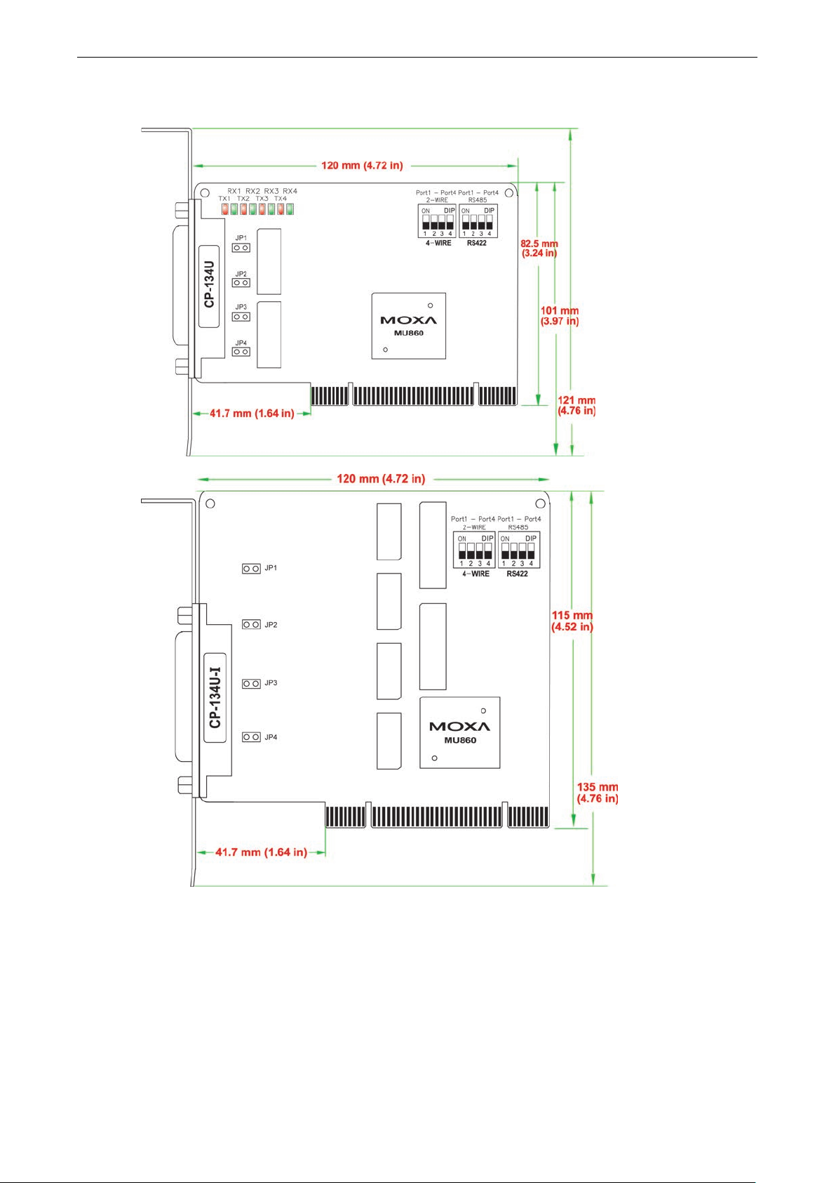
CP-134U/CP-134U-I
Onboard termination resistors can be activated individually for each serial port using jumpers JP1 through JP4.
For CP-134U, JP1/2/3/4 corresponds to serial port 1/2/3/4, respectively. For CP-134U-I, JP1/2/3/4
corresponds to serial port 4/3/2 /1, respectively. Short the jumper pins to activ ate the termination resistor ;
leave the jumper pins open to bypass the termination res is tor .
The on board DIP switches, S1 and S2, ar e used to s elect RS-422 or RS-485 mode for each serial port. Switches
1 through 4 on each bank correspond to the 4 serial ports. S2 selects between RS-422 and RS-485; S1 selects
between 2-wire and 4-wire RS-485. In addition, ports 1 and 2 can be set individually to RS-232 mode using the
on-board 30-pin jumpers, as follows:
Page 19
Universal PCI Board Hardware Installation
2-8
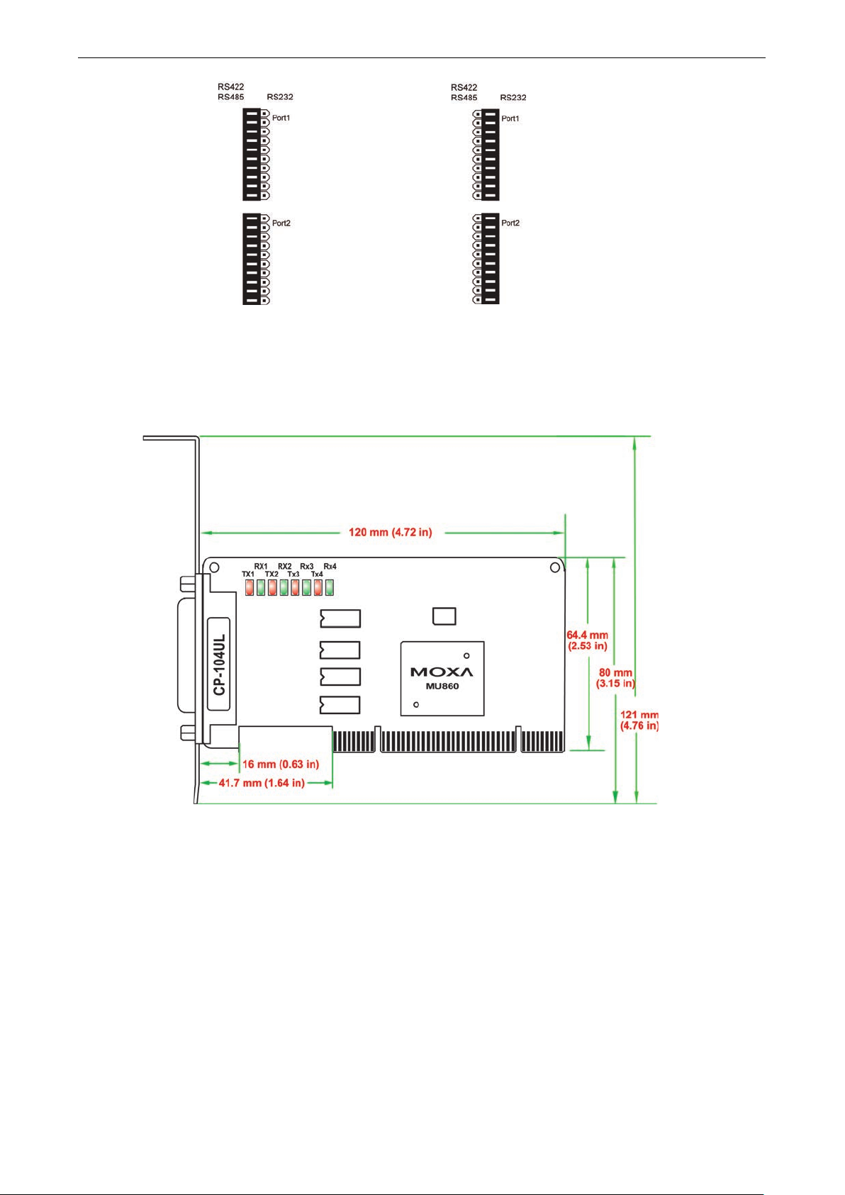
RS
Use the jumper to cover the left
two columns of jumper pins.
RS
Use the jumper to cover the right
two columns of jumper pins.
-422 or RS-485 mode:
CP-104UL
-232 mode:
This board does not require configuration.
Page 20
Universal PCI Board Hardware Installation
2-9
Step
The top row of jumper pins selects the
the bottom row of jumper pins selects the source of 5V
power:
Step
For each serial port, a set of 5 jumper
pins is used
is sent to pin 9.
CP-104JU
This board does not require configuration.
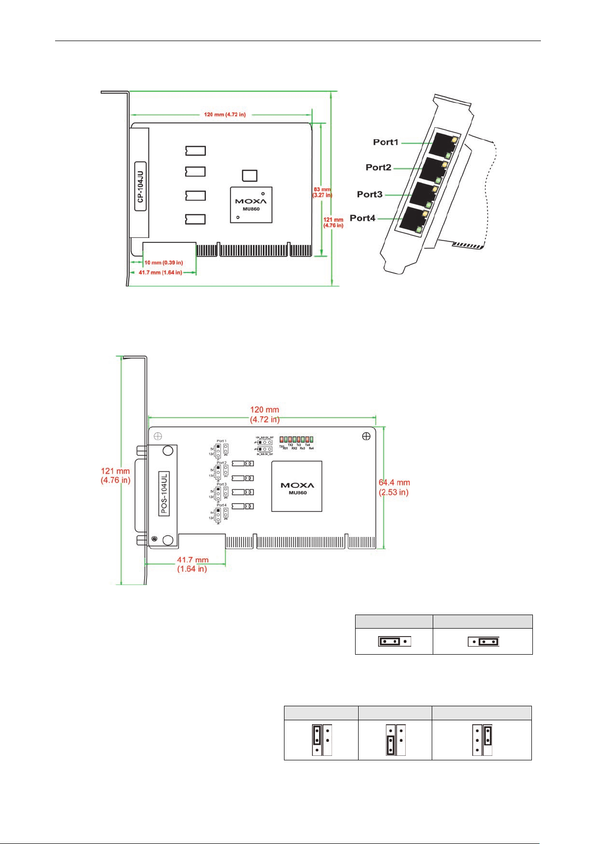
POS-104UL
The onboard jumpers are used to specify the pin 9 power signal for eac h serial po rt.
a
source of 12V power;
Bus power External power
If 5V or 12V external power is enabled, you will need to connect the cable from the back of POS-104UL to the
PC’s power supply. Remove both jumpers to disable all power signals to all ports.
b
select the power signal that
To disable pin 9 power signals for a specific port, remove the j umper.
5V 12V RI signal (input)
Page 21
Universal PCI Board Hardware Installation
2-10
4-Wire RS-485
OFF
OFF
ON
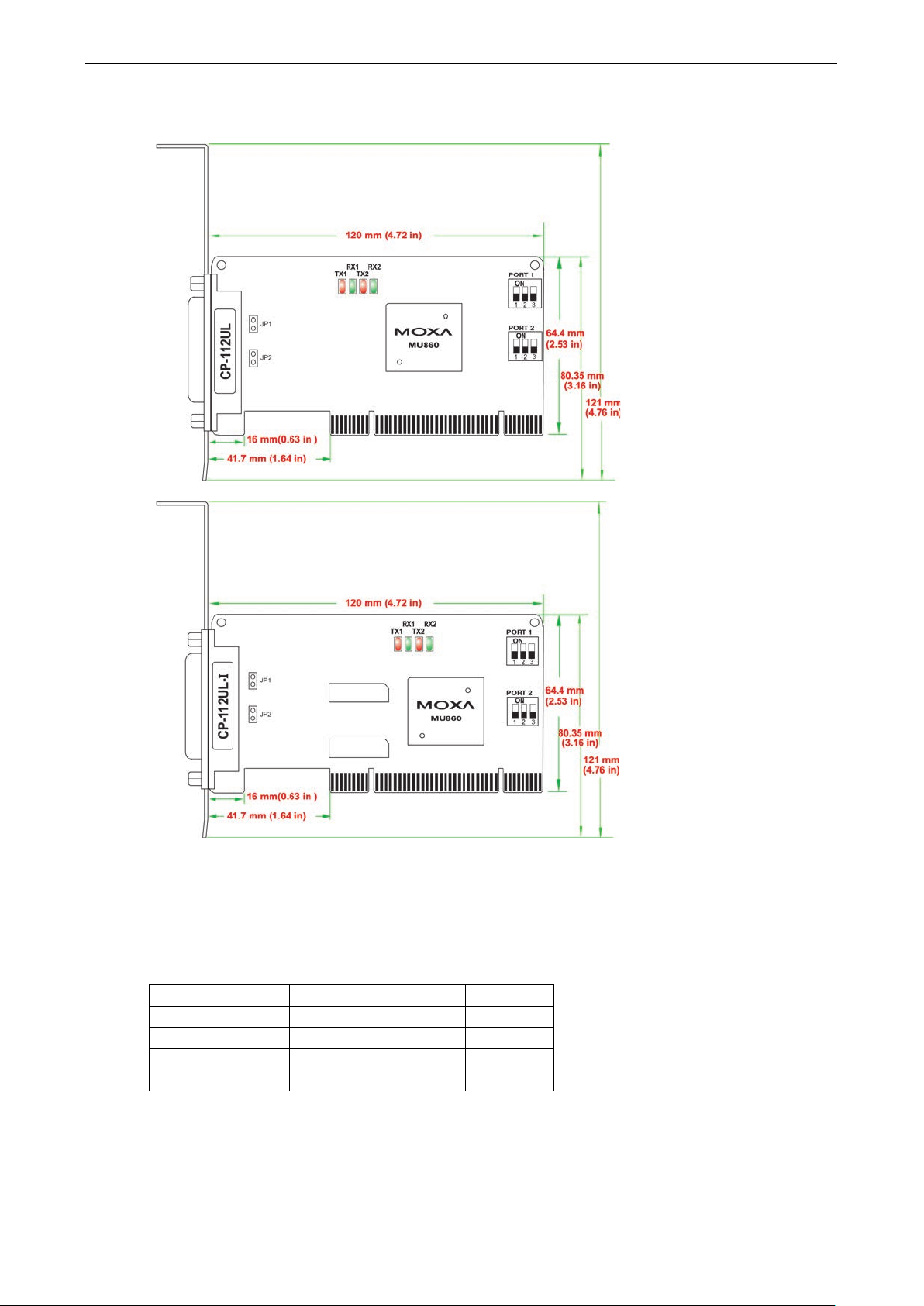
CP-112UL/CP-112UL-I
Onboard termination resistors can be activated individually for each serial port using jumpers JP1 and JP2. JP1
corresponds to serial port 1. Short the jumper pins to activate the termination resistor; leave the jumper pins
open to bypass the termination resistor. The onboard DIP switches, S1, S2, and S3, are used to select RS-232,
RS-422, or RS-485 mode for each serial port. Switch 1 corresponds to port 1 and switch 2 corresponds to port
2. S1 selects between R S-232, S2 selects between RS-422, a nd S3 selects bet ween 2-wire and 4-wire RS-485,
as follows:
Mode S1 S2 S3
RS-232 ON -- --
RS-422 OFF ON --
2-Wire RS-485 OFF OFF OFF
Page 22
Universal PCI Board Hardware Installation
2-11
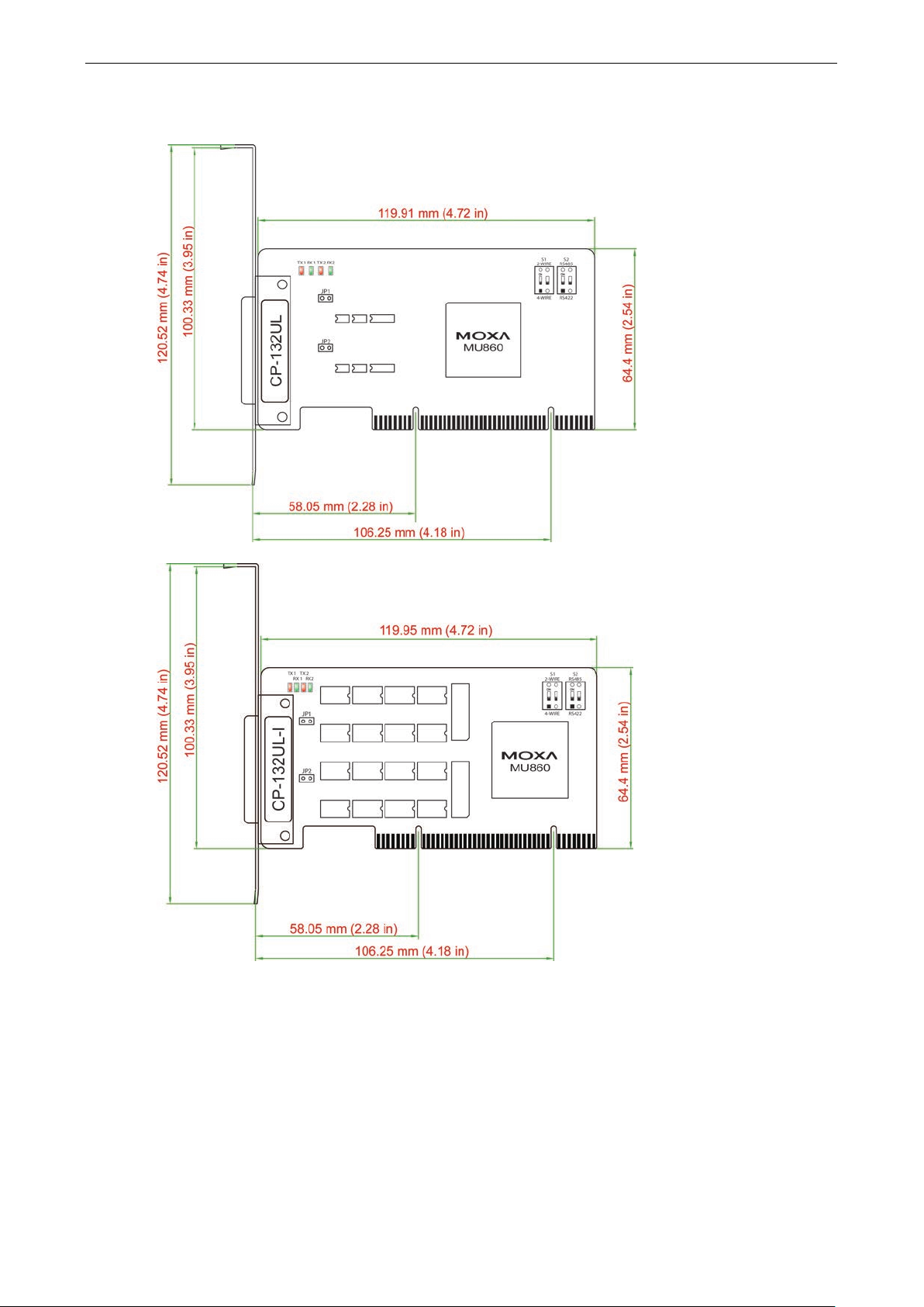
CP-132UL/CP-132UL-I
Onboard termination resistors can be activated individually for each serial port using jumpers JP1 and JP2. JP1
corresponds to serial port 1. Short the jumper pins to activate the termination resistor; leave the jumper pins
open to bypass the termination resistor.
The onboard DIP switches, S1 and S2, are used t o select R S-422 or RS-4 85 mode for each serial port. On each
bank, switch 1 corresponds to port 1 and switch 2 corresponds to por t 2. S2 selects between RS-422 and
RS-485; S1 selects between 2-wire and 4-wire RS-485.
Page 23
Universal PCI Board Hardware Installation
2-12
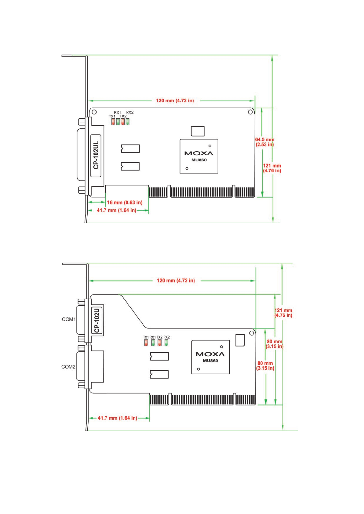
CP-102UL
This board does not require configuration.
CP-102U
This board does not require configuration.
Page 24
Universal PCI Board Hardware Installation
2-13
NOTE
When configuring two or more CP-102UF boards installed in the same computer, please pay attentio n to the
model names of the boards. The two models can be recognized by the type of connector on the board. Model
CP
CP-102UF
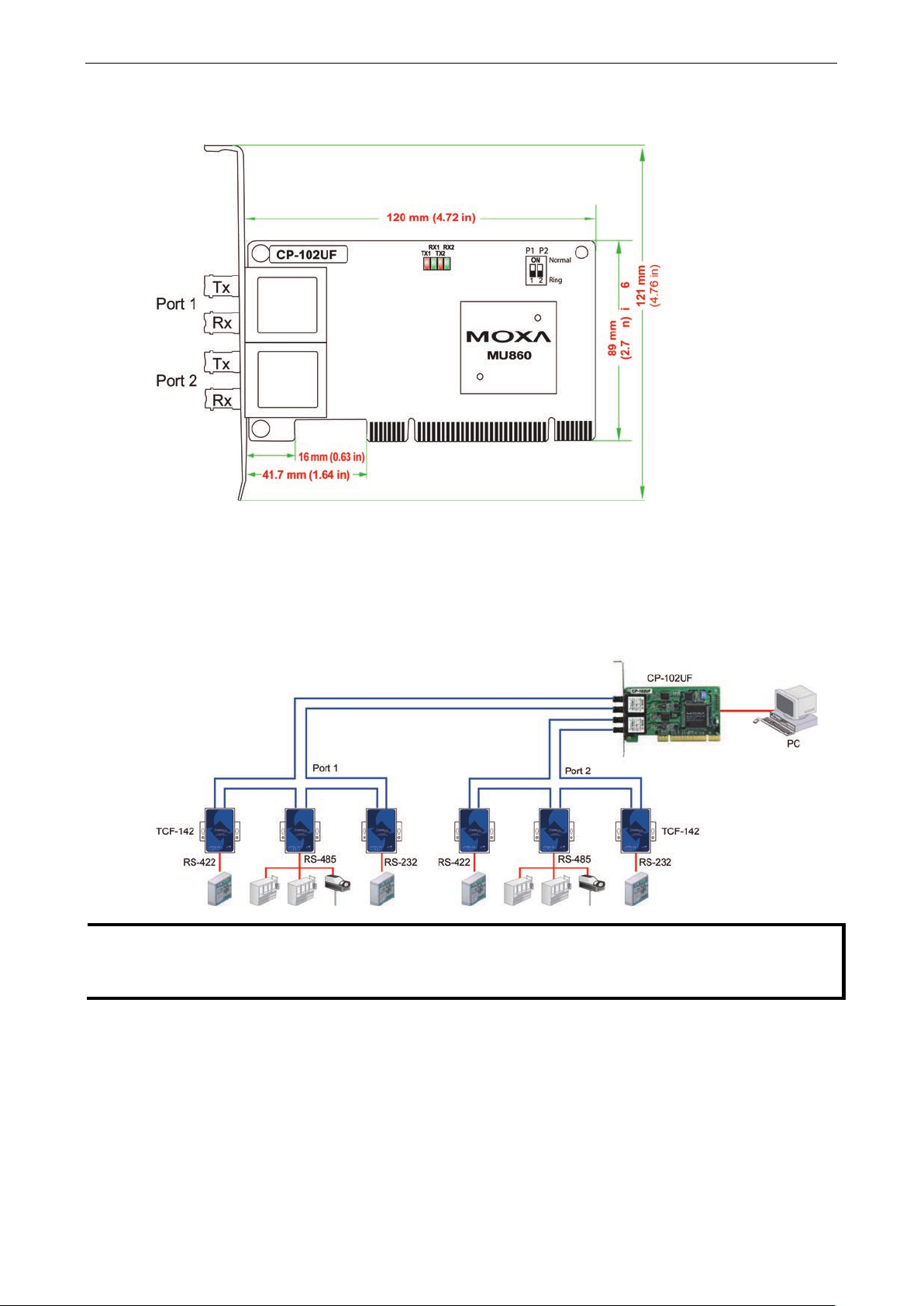
The onboard DIP switches are used to configure the CP-102UF for “Ring mode” or “Nor mal”. Whe n us ing the
CP-102UF board, your PC can be included as one node of a fiber ring formed using Moxa’s own TCF-142
serial-to-fiber converter. Since each TCF-142 has two fiber ports and one serial port, PCs that are part of the
ring will be able to communicate with serial devic es conne cted to the ring. Note that the Tx port of the
CP-102UF connects to a neighboring converter’s Rx port to form the ring. When one node trans mits a signal,
the signal travels around the ring until it returns back to the transmitting unit, w hi c h then blocks the signals .
-102UF-M uses plastic ST connectors, whereas model CP-102UF-S uses metal ST connectors.
Page 25

Universal PCI Board Hardware Installation
2-14
ATTENTION
Safety First!
To avoid damaging your system and board, make sure your PC’s power is tur ned off before ins talli ng y our
Universal PCI Board.
Step 1:
Power off the PC.
Step 2:
Shut off the power to any peripheral devices and remove the PC’ s
Step 3:
Configure the UPCI board’s DIP switches and jump ers as nece s s ary . T his only appl ie s to certa in
models. For additional information, pl e as e ref er to yo ur model in this c hapte r .
Step
Insert the board firmly into a free PCI or PCI
Step 6:
Use a screw to secure the board in place.
Step 7:
Replace the PC’s cover.
Step 8:
Power on the PC. The BIOS will automatically set the IRQ and I/O addr ess .
Step 9:
Install the software. For details, ple ase refe r to the appro pr iate
Plugging the Board into an Expansion Slot
4:
cover.
-X slot on the PC.
chapter for your operating system.
Page 26

3
3. Software Installation
This chapter gives installation, c o nfig uration, and update/removal procedures for the drive r for Windows
Server 2012 (64-bit), Windows 8 (32-bit/64-bit), Windows 7 (32-bit/64-bit), Windows 2003/XP/Vista/2008
(32-bit/64-bit), Windows 2000, WinCE, DOS, Linux (32-bit/64-bit), and SCO. Before proceeding with the
software installation, comp le te the hard w are installa tio n discussed in the previous chapter, “Hardwar e
Installation.”
Refer to the next chapter, “Serial Progr amming Tools,” for information about developing your own serial
programming applications. Note that you can install up to 4 PCI Express boards in one system, provided
sufficient I/O address and IRQ number resources are av aila ble.
You can download the drivers from the Moxa website.
The following topics are covered in this chapter:
Windows Drive r s
Windows 7/8 (32-bit/64-bit)
Wind ows 2008/Vista (32-bit/64-bit)
Wind ows 2003/XP
Wi ndows 2000
Wind ows NT
Wind ows 95/98/ME
Wind ows CE
Non Windows Driver
DOS
Linux (32-bit/64-bit)
SCO
Page 27
Universal PCI Board Software Installation
3-2
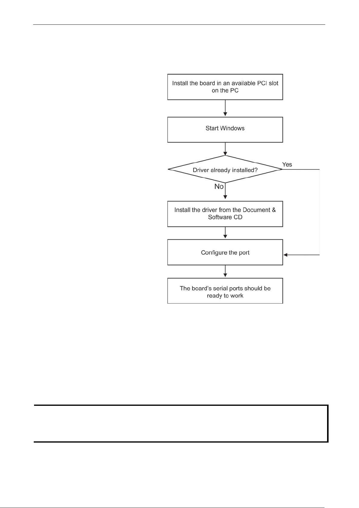
The overall procedure for installing the
drivers is shown on the right. A newly
installed board will be automatically
detect
NOTE
If you have already installed a
additional boards, Windows 8 will automatically detect and install the new board(s) the next time you boot up
the computer. In this case, proceed directly to the next section, “Configuring the Ports,” to configure the ports’
serial transmission parameters.
Windows Drivers
Moxa provides drivers that allow you to use the following serial board products under Windows 7/8, Windows
2008/Vista/2003/XP/2000.
ed by the operating system.
Windows 7/8 (32-bit/64-bit)
The Windows 8 installation procedure s and popup windows are almost the same as Windows 7. Thus, in this
section, we describe the installation proc ed ur e for Windo w s 8 as an example.
Installing the Driver
The following procedure describes how to ins tall the CP-104U driver for the firs t tim e with Windows 8. First,
make sure that you have already plugged the board or boards into the system ’ s PCI or PCI-X slot(s).
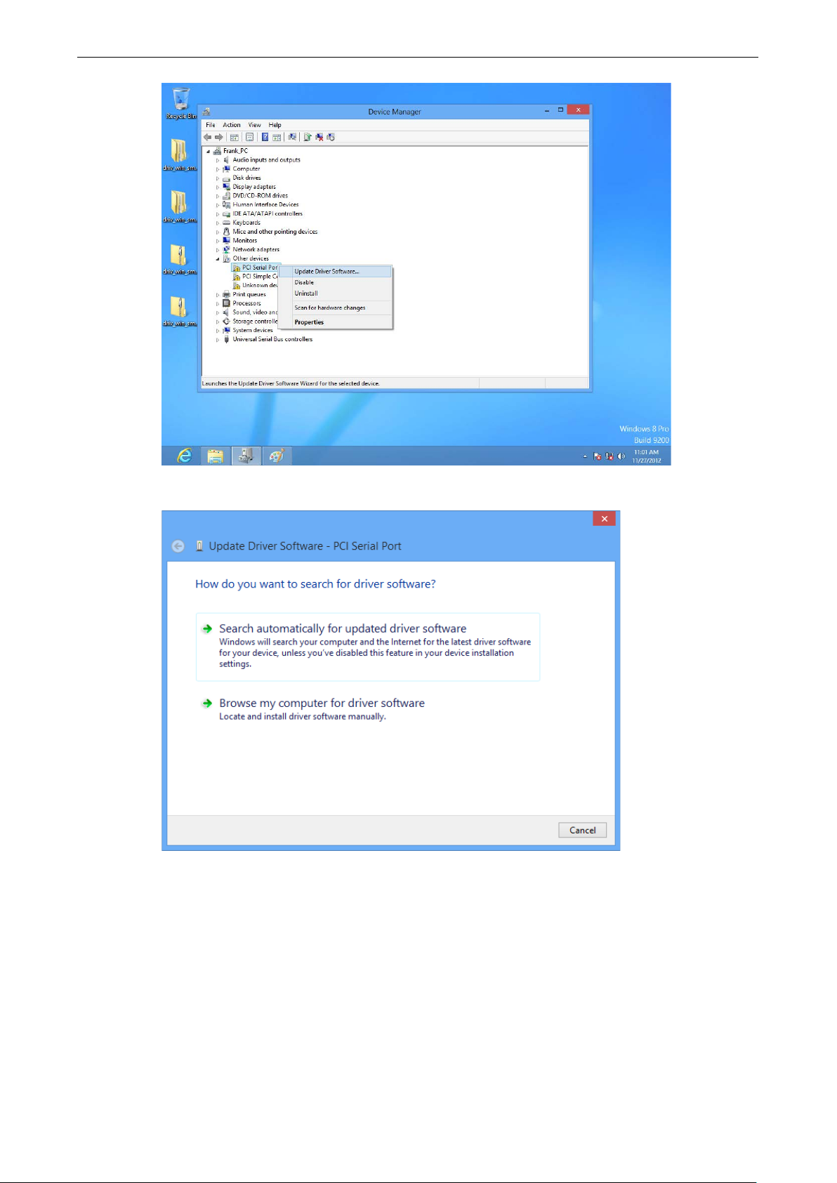
1. Go to Device Manager/Other devices to install the PCI Serial Port driver. Right click on the PCI Serial
port. Windows will offer to connect to the Windows update site to search for a driver. Select Update Driver
Software….
CP-104U or other Moxa UPCI board in your computer, and you are installing
Page 28
Universal PCI Board Software Installation
3-3
2. Select Browse my computer for device software to continue.
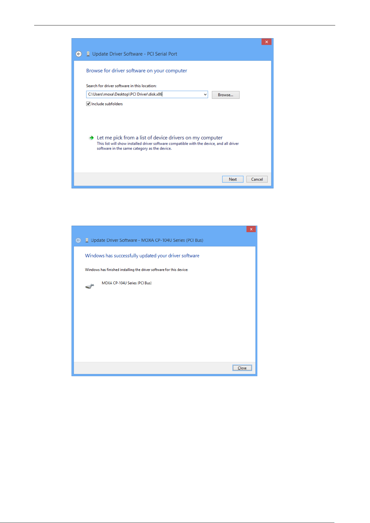
3. Select Search for driver software in this location, select Include subfolde rs, and then click Browse.
If the system is a 32-bit (x86) platform, navigate to the \CP-104U Series\Software\Windows 8\x86
folder on the CD. If the system is a 64-bit (x64) platform, navigate to the \CP-104U
Series\Software\Windows 8\x64 folder on the CD, and then click Next to continue.
The following figure shows the path for x86.
Page 29
Universal PCI Board Software Installation
3-4
4. Wait while the driv er softw are is ins tall e d . The nex t wind ow show s the model nam e of the board, and
indicates that Windows has completed the driver ins tallati o n. Click Close to proceed with the rest of the
installation procedure .
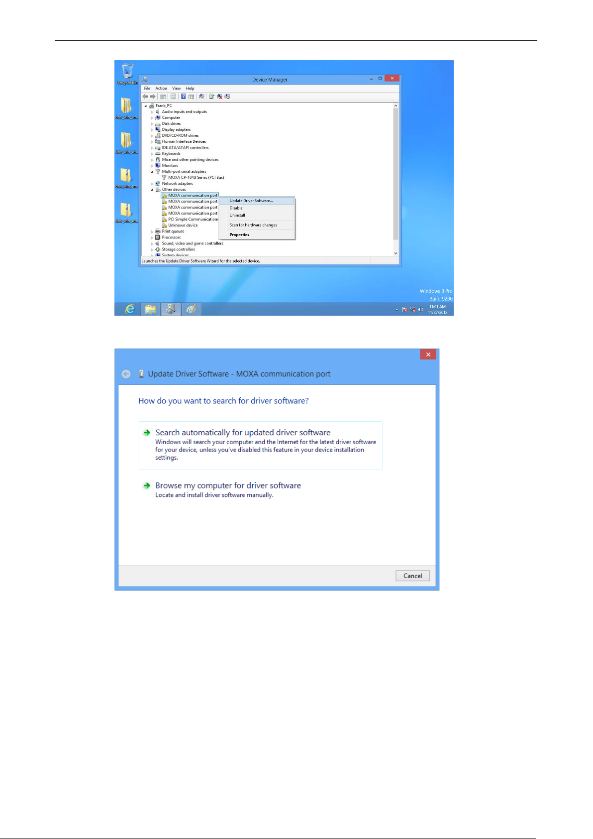
5. After installing the m ultip ort serial adaptors driver, install the Moxa Port diver next. Right click on MOXA
communication port. A popup window will open to help you install the driver for MOXA Por t 0. Select
Update Driver Software…
Page 30
Universal PCI Board Software Installation
3-5
6. Select Browse my computer for device software to continue.
7. Select Search for driver software in this location, select Include subfolde rs, and then click Browse.
If the system is a 32-bit (x86) platform, navigate to the \CP-104U Series\Software\Windows 8\x86
folder on the CD. If the system is a 64-bit (x64) platform, navigate to the \CP-104U
Series\Software\Windows 8\x64 folder on the CD, and then click Next to continue.
The following figure shows the path for x86.
Page 31

Universal PCI Board Software Installation
3-6
8. After all files have been copied to the system, window showing Windows has successfully updated your
driver software will open to indicate that it has finished installing MOXA Port 0. The Port installation
procedure is complete when Port 0 has been set up.
Page 32

Universal PCI Board Software Installation
3-7
Configuring the Ports
After the driver has been installed, use Device Manager to conf igure the CP-104U serial ports.
1. Expand the Multi-port serial adapters tab, right click MOXA CP-104U Series (PCI Bus), and then click
Properties to open the board’s config uration panel.
Page 33

Universal PCI Board Software Installation
3-8
2. Click the port you would like to conf igure to highlight it, and then click Port Setting.
3. Select a COM number for the port from the Port Number pull-dow n li s t. S e le c t the Auto Enumerating
COM Number option to map subsequent por ts autom atic a lly . T he port numbers will b e assigne d in
sequence. For example, if COM 3 is assigned to Port 1, then COM 4 (if not already occupied) will be assigned
to Port 2, etc.
Page 34

Universal PCI Board Software Installation
3-9
Tx FIFO
Rx FIFO
High
128
120
Middle
64
60
Low 1 1
4. Select an Rx FIFO Trigger from the Rx FIFO Level pull-down list. Rx FIFO trigger levels of High, Middle,
and Low are available, with the default set to High (120 bytes). Select Set the change to all ports option
to apply this Rx FIFO Trigger to all ports.
5. Select a Tx FIFO Level from the Tx FIFO Level pull-down list. Tx FIFO Levels of High, Middle, and Low
are available, with the default set to High (128 bytes). Select Set the change to all ports option to apply
the just defined Tx FIFO Size to all ports.
6. Click OK to save the port settings, and then click OK in the Properties window to finish the port settings
procedure.
Removing the Driver
1. Go to Device Manager. Remove port driver fir s t, and then re mov e UPCI driver to prevent occupying the
port number. Expand Ports (COM & LPT) tab, right click MOXA Communication Port 1, and then click
Uninstall to remove port driver. Repeat same procedure until all ports driver are complete removed.
Page 35

Universal PCI Board Software Installation
3-10
2. Expand Multi-port Serial Adapters tab, right click CP-104U Serie s, and then click Uninstall to remove
the UPCI driver.
3. The Device Manager window refreshes automatically, showing that the driver and ports for the CP-104U
Series board have been removed.
Page 36

Universal PCI Board Software Installation
3-11
CP-102UL
CP-104UL
CP-168U
ATTENTION
The following steps will not be necessary if a Moxa UPCI board was alre ady installe d on your
Windows will automatically detect and install any additional board(s) at bootup. In this case, you may proceed
directly to
Windows 2008/Vista (32-bit/64-bit)
In this section, we describe the installation procedure for Windows Vista. The installation proc edure for
Windows 2008 is similar.
2 Ports 4 Ports 8 Ports
CP-112UL/CP-112UL-I CP-114UL/CP-114UL-I CP-118U/CP-118U-I
CP-132UL/CP-132UL-I CP-134U/CP-134U-I CP-138U/CP-138U-I
CP-102U CP-104JU
CP-102UF POS-104UL
Windows 2008 and Windows Vista support up to 256 serial ports from COM1 to COM256. In order to m ake the
best use of Windows 2008/Vista’s multi-process/multi-thread advanced features, 32-bit and 64-bit Windows
2008/Vista device driver s were develope d for Moxa multiport boards. The drivers conform to the Win32 COMM
API standard.
Installing the Driver
The following instructions show how to install the driver for the first time under Windows 2008/Vista. You will
need to plug the board in an available PCI or PCI-X slot first, bef or e installing the driver.
configuring the ports.
Note that these instructions use the CP-118 U as an example. The proc edure for installing all models is the
same.
1. After the board is physically installed and the PC boots up, Windows will automatically detect the new board.
The Found New Hardware Wizard window will open auto matically . S e l e c t Locate and install driver
software (recommended).
computer.
Page 37

Universal PCI Board Software Installation
3-12
Page 38

Universal PCI Board Software Installation
3-13
2. Select I don’t have the disc. Sho w me other options.
3. Select Browse my computer for driver software (advanced).
Page 39

Universal PCI Board Software Installation
3-14
4. Click Browse and select the appropriat e directory on the Document & Software CD for the driver. Drivers
for all operating systems are located under the prod uc t fo lder in the \Software directory (e.g., under
\CP-118U Series \Software).
For 32-bit (x86) platfor ms, select the \Windows 2008_Vista\x86 folder.
For 64-bit (x64) platfor ms, select the \Windows 2008_Vista\x64 folder.
After selecting the folder, click Next to continue.
5. If you receive a warning message stating that the Windows can’t verify the publisher of the software, select
Install this driver software anyway.
Page 40

Universal PCI Board Software Installation
3-15
6. After the drivers have been ins tall e d , c lic k Close to exit the wizard.
Installing the Ports
After the board and drivers have been installed, an installation wizard will guide you through installation of the
newly added serial ports, star ting wi th port 0.
7. When prompted to inser t a disc, se le c t I don’t have the disc. Show me other options.
Page 41

Universal PCI Board Software Installation
3-16
8. Select Browse my computer for driver software (advanced).
9. Click Browse and select the appropriate directory on the Document & Software CD for the driver. Drivers
for all operating systems are located under the prod uc t fo lder in the \Software directory (e.g., under
\CP-118U Series \Software). For 32-bit (x86) platforms, select the \Windows 2008_Vista\x86 folder.
For 64-bit (x64) platforms, select the \Windows 2008_Vista\x64 folder. After selecting the folder, click
Next to continue.
Page 42

Universal PCI Board Software Installation
3-17
10. If you receive a warning message stating that the Windows can’t verify the publisher of the software, select
Install this driver software anyway.
11. After the drivers have been installed, click Close to exit the wizard. The other serial ports will
automatically install in the background.
Page 43

Universal PCI Board Software Installation
3-18
Verifying the Installation
You can use Windows Device Manager to verify proper installation.
1. Under My Computer, click System Properties.
2. In the System window, click Device Manager.
Page 44

Universal PCI Board Software Installation
3-19
3. In the Device Manager window, you should see the UPCI board under Multi-port serial adapters
(CP-118U in this example). You should also see Moxa communication ports under Ports (COM & LPT ).
4. If you see any special marks, such as a question mark or an exclamation mark, next to the Moxa items, the
installation of your module or serial ports was not succe s sful. Examine the Windows event log for details.
Page 45

Universal PCI Board Software Installation
3-20
High
128
120
Configuring the Ports
After the board and serial port drivers are installed, the board’s Properties window will appear. The system will
map the ports automatically. You may be prompted to take care of port configuration if other Mo xa boards have
been installed.
1. On the Ports Configuration tab, select a port to configure and click Port Setting.
2. Under Port Number, select a COM number to assign to the serial por t. Select Auto Enumerating COM
Number to map subsequent ports in numerical order. For example, if COM 3 is assigned to Port 1, then
COM 4 will be automatically assigned to Port 2.
Select an Rx FIFO Trigger and Tx FIFO Size. The default Rx FIFO T ri gger is 120 bytes (high level). The
default Tx FIFO Size is 128 bytes (high level). Select Set the change to all ports to use this setting for all
serial ports on the board.
Tx FIFO Rx FIFO
Middle 64 60
Low 1 1
3. Click OK to approve the settings for th e selected port. Continue in the same way to configure the other ports.
When you have finished setting up the ports, click OK to close the Properties window and apply the new
port settings.
Page 46

Universal PCI Board Software Installation
3-21
Disabling the Board
1. Right-click My Computer and select Properties in the context menu.
2. In the System window, click Devi c e Manager.
3. In Device Mana ger, right-click the UPCI board under Multi-port serial adapters and select Disable in
the context menu. This will disable the board.
Page 47

Universal PCI Board Software Installation
3-22
CP-102UF
POS-104UL
Uninstalling the Board
1. Right-click My Computer and select Properties in the context menu.
2. In the System window, click Devi c e Manager.
3. Right-click the UPCI board under Multi-port serial adapters (CP-118U in this example) and select
Uninstall in the context menu.
4. A confirmation d ialog will ap pea r . Clic k OK to uninstall the device.
Windows 2003/XP
This chapter explains how to install, configure, update, and remove the board drivers for Windows XP/2003.
The following models are supported:
2 Ports 4 Ports 8 Ports
CP-112UL/CP-112UL-I CP-114UL/CP-114UL-I CP-118U/CP-118U-I
CP-132UL/CP-132UL-I CP-134U/CP-134U-I CP-138U/CP-138U-I
CP-102UL CP-104UL CP-168U
CP-102U CP-104JU
Page 48

Universal PCI Board Software Installation
3-23
ATTENTION
The following steps will not be necessary if a Moxa UPCI board was alre ady installe d on your
Windows will automatically detect and install any additional board(s) at bootup. In this case, you may proceed
directly to
Windows XP/2003 supports up to 256 serial ports, from COM1 to COM256. Moxa developed pure 32 and 64-bit
Windows device drivers in order to fully utilize the adv a nc ed multi-process and multi-thread features of
Windows XP/2003. The drive rs co nfo r m to the Win32 CO MM API standard.
Installing the Driver
The following instructions show how to instal l the dri ver fo r the fir s t time under Wind ow s XP. The same
procedure is used for Windows 2003. You will need to plug the board in an availabl e PCI or PCI-X slot first,
before installing the driver.
configuring the ports.
Note that these instructions use the CP-118U as an example. The proc edure for installing all models is the
same.
1. After the board is physically installed and the PC boots up, Windows will automatically detect the new board.
The Found New Hardware Wizard window will open automatically. When prompted to connect to Windows
Update, select. No , not this time and click Next to continue.
computer.
Page 49

Universal PCI Board Software Installation
3-24
2. Select Install from a list or specific location (Advanced) and click Next to continue.
3. Select Search for the best dri ver in these locations and Include this location in the search. Click
Browse and select the appropriate directory on the Document & Software CD for the driver .
Drivers for all operating systems are located under the product folder in the \Software directory (e.g., under
\CP-118U Series \Software). For 32-bit (x86) platforms, select the \Windows XP_2003\x86 folder. For
64-bit (x64) platforms, select the \Windows XP_2003\x64 folder. After selecting the folder, click Next
to continue.
Page 50

Universal PCI Board Software Installation
3-25
4. If you see a warning that the software has not pass ed Wi ndows Logo testing, click Continue Anyway.
5. Windows will instal l the dri v ers. Whe n the ins tallati o n is comple te , c lic k Finish.
Page 51

Universal PCI Board Software Installation
3-26
Installing the Ports
After the board and drivers have been installed, an installation wizard will guide you through installation of the
newly added serial ports, starting wi th port 0.
1. When prompted to connect to Window s Update, s e lect No, not this time and click Next to continue.
Page 52

Universal PCI Board Software Installation
3-27
2. Select Install from a list or specific location (Advanced) and click Next to continue.
3. Select Search for the best driver in these locations and Include this location in the search. Click
Browse and sel ect th e appropriate directory on the Document & Software CD for the driver. Drivers for all
operating systems are located under the product folder in the \Software directory (e.g., under \CP-118U
Series\Software).
For 32-bit (x86) platfor ms, select the \Windows XP_2003\x86 folder.
For 64-bit (x64) platfor ms, select the \Windows XP_2003\x64 folder.
After selecting the folder, click Next to continue.
Page 53

Universal PCI Board Software Installation
3-28
4. If you see a warning that the software has not pass ed Wi ndows Logo testing, click Continue Anyway.
5. After the drivers for the serial port have been installed, click Finish to close the wizard. Repeat this process
for the remaining serial ports.
Page 54

Universal PCI Board Software Installation
3-29
Verifying the Installation
You can use Windows Device Manager to verify proper installation of the board.
1. Right-click My Computer and select Properties in the context menu.
2. In the Hardware tab, click Device Manager.
Page 55

Universal PCI Board Software Installation
3-30
3. In the Device Manager window, you should see your UPCI board under Multi-port serial adapters
(CP-118U in this example). You should also see Moxa communication ports under Ports (COM & LPT).
4. If you see any special marks, such as a question mark or an exclamation mark, next to the Moxa items, the
installation of the board was not successful. Examine the Windows ev e nt log for de tai ls .
Page 56

Universal PCI Board Software Installation
3-31
High
128
120
Configuring the Ports
After the board and serial port drivers are installed, the board’s Properties window will appear. The system will
map the ports automatically. You may be prompted to take care of port configuration if other Mo xa boards have
been installed.
1. On the Ports Configuration tab, select a port to configure and click Port Setting.
2. Under Port Number, select a COM number to assign to the serial por t. Select Auto Enumerating COM
Number to map subsequent ports in numerical order. For example, if COM 3 is assigned to Port 1, then
COM 4 will be automatically assigned to Port 2.
3. Select an Rx FIFO Trigger and Tx FIFO Size . The default Rx FIFO Trigger is 120 bytes (high level). The
default Tx FIFO Size is 128 bytes (high level). Select Set the change to all ports to use this setting for all
serial ports on the board.
Tx FIFO Rx FIFO
Middle 64 60
Low 1 1
4. Click OK to approve the settings fo r the selected port. Continue in the same way to configure the other ports.
When you have finished setting up the ports, click OK to close the Properties window and apply the new
port settings.
Page 57

Universal PCI Board Software Installation
3-32
Using PComm
PComm Diagnostic is a useful program for checking the board’s status. It provides internal and external testing
of IRQ, Tx D/RxD, U ART, CTS/RTS, DTR/DSR, and other items. You can use PComm Diagnostic to verify that the
module and serial ports are working properly.
You may download PComm from the Moxa website.
Using Event Log
You may refer to the Windows event log to verify operatio n of the board. To view the event log, open Event
Viewer, which is located under Administr ative Tools in the Control Panel. Information about the board will be
located under the System category.
Disabling the Board
1. Right-click My Computer and select Properties in the context menu.
2. In the Hardware tab, click Device Manager.
Page 58

Universal PCI Board Software Installation
3-33
3. In Device Mana ger, right-click the UPCI board under Multi-port serial adapters and select Disable in
the context menu. This will disable the board.
Uninstalling the Board
1. Right-click My Computer and select Properties in the context menu.
2. In the Hardware tab, click Device Manager.
Page 59

Universal PCI Board Software Installation
3-34
3. Right-click the UPCI board under Multi-port serial adapters (CP-118U in this example) and select
Uninstall in the context menu.
4. A confirmation d ialog will appear. Click OK to uninstall the de v i ce.
Windows 2000
This chapter explains how to install, configure, update, and remove the board drivers for Windows 2000. The
following models are supported:
2 Ports 4 Ports 8 Ports
CP-112UL/CP-112UL-I CP-114UL/CP-114UL-I CP-118U/CP-118U-I
CP-132UL/CP-132UL-I CP-134U/CP-134U-I CP-138U/CP-138U-I
CP-102UL CP-104UL CP-168U
CP-102U CP-104JU
CP-102UF POS-104UL
Page 60

Universal PCI Board Software Installation
3-35
ATTENTION
The following steps will not
Windows will automatically detect and install any additional board(s) at bootup. In this case, you may proceed
directly to
Windows 2000 supports up to 256 serial ports, from COM1 to COM256. Moxa developed pure 32-bit Windows
device drivers in order to fully utilize the advanced multi-process and multi-thread features of Windows 2000.
The drivers conform to the Win32 COMM API standard.
You can download the drivers from the Moxa website. For information on developing your own serial
programming applications, please refer to Chapter 9.
Before installing the software, be sure to install the hardware first. For details on installing the hardware, please
refer to Chapter 2.
Installing the Driver
The following instructions show how to install the driver for the first time under Windows 2000. You will need
to plug the board in an available PCI or PCI-X slot first, befor e installing the driver.
configuring the ports.
Note that these instructions use the CP-118U as an example. The procedure for installing all models is the
same.
1. After the board is physically installed and the PC boots up, Windows will automatically detect the new board
and the Found New Hardware Wizard window will open automatically. Click Next to continue.
be necessary if a Moxa UPCI board was already installed on your computer.
Page 61

Universal PCI Board Software Installation
3-36
2. Select Search for a suitable driver for my device (recommended) and click Next to continue.
3. Select Specify a location and click Next to continue.
4. Click Browse and select the appropriate directory on the Document & Software CD fo r the driver. Drivers
for all operating systems are located under the prod uc t fo lder in the \Software directory (e.g., under
\CP-118U Series \Software). Select the \Windows 2K folder and click Next to continue.
Page 62

Universal PCI Board Software Installation
3-37
5. After the wizard has loc ated the driv er file s , c lick Next to proceed.
6. If you see a warning that the digital sig nature has not been found, click Yes to proceed.
Page 63

Universal PCI Board Software Installation
3-38
7. Windows will instal l the dri v ers. Whe n the ins tallati o n is comple te , c lic k Finish.
Installing the Ports
After the board and drivers have been installed, an installation wizard will guide you through installation of the
newly added serial ports, starting wi th port 0.
1. When the installation w iza r d ope ns , c li ck Next to proceed.
Page 64

Universal PCI Board Software Installation
3-39
2. Select Search for a suitable driver for my device (recommended) and click Next to continue.
3. Select Specify a location and click Next to continue.
4. Click Browse and select the appropriate directory on the Document & Software CD for the driver. Drivers
for all operating systems are located under the prod uc t fo lder in the \Software directory (e.g., under
\CP-118U Series \Software). Select the \Windows 2K folder and click Next to continue.
Page 65

Universal PCI Board Software Installation
3-40
5. After the wizard has loc ated the driver files, click Next to proceed.
6. After the drivers have been installed, click Finish to exit the wizard. The other serial ports will automatically
install in the background.
Verifying the Installation
You can use Windows Device Manager to verify proper installation of the board.
1. Right-click My Computer and select Properties in the context menu.
Page 66

Universal PCI Board Software Installation
3-41
2. In the Hardware tab, click Device Manager.
3. In the Device Manager window, you should see your UPCI board under Multi-port serial adapters
(CP-118U in this example). You should also see Moxa communication ports under Ports (COM & LPT).
4. If you see any special marks, such as a question mark or an exclamation mark, next to the Moxa items, the
installation of the board was not successful. Examine the Windows ev e nt log for de tai ls .
Page 67

Universal PCI Board Software Installation
3-42
Configuring the Ports
After the board and serial port drivers are installed, the board’s Properties window will appear. The system will
map the ports automatically. You may be prompted to take care of port configuration if other Mo xa boards have
been installed.
1. On the Ports Configuration tab, select a port to configure and click Port Setting.
2. Under Port Number, select a COM number to assign to the serial por t. Select Auto Enumerating COM
Number to map subsequent ports in numerical order. For example, if COM 3 is assigned to Port 1, then
COM 4 will be automatically assigned to Port 2.
3. Select an Rx FIFO Trigger and Tx FIFO Size . The default Rx FIFO Trigger is 120 bytes (high level). The
default Tx FIFO Size is 128 bytes (high level). Select Set the change to all ports to use this setting for all
serial ports on the board.
Tx FIFO Rx FIFO
High 128 120
Middle 64 60
Low 1 1
4. Click OK to approve the settings fo r the selected port. Continue in the same way to configure the other ports.
When you have finished setting up the ports, click OK to close the Properties window and apply the new
port settings.
Page 68

Universal PCI Board Software Installation
3-43
Using PComm
PComm Diagnostic is a useful program for checking the board’s status. It provides internal and external testing
of IRQ, TxD/RxD, UART, CTS/RTS, DTR/DSR, and other items. You can use PComm Diagnostic to verify that the
module and serial ports are working properly.
You may download PComm from the Moxa website.
Using Event Log
You may refer to the Windows event log to verify operation of the board. To view the event log, open Event
Viewer, which is located under Administr ative Tools in the Control Panel. Information about the board will be
located under the System category.
Disabling the Board
1. Right-click My Computer and select Properties in the context menu.
2. In the Hardware tab, click Device Manager.
Page 69

Universal PCI Board Software Installation
3-44
3. In Device Mana ger, right-click the UPCI board under Multi-port serial adapters and select Disable in
the context menu. This will disable the board.
Uninstalling the Board
1. Right-click My Computer and select Properties in the context menu.
2. In the Hardware tab, click Device Manager.
Page 70

Universal PCI Board Software Installation
3-45
CP-102UF
POS-104UL
3. Right-click the UPCI board under Multi-port serial adapters (CP-118U in this example) and select
Uninstall in the context menu.
4. At the warning prompt, click OK to uninstall the devic e .
Windows NT
This chapter explains how to install, configure, update, and remove the board drivers for Windows NT. The
following models are supported:
2 Ports 4 Ports 8 Ports
CP-112UL/CP-112UL-I CP-114UL/CP-114UL-I CP-118U/CP-118U-I
CP-132UL/CP-132UL-I CP-134U/CP-134U-I CP-138U/CP-138U-I
CP-102UL CP-104UL CP-168U
CP-102U CP-104JU
Page 71

Universal PCI Board Software Installation
3-46
Windows NT supports up to 256 serial ports, from COM1 to COM256. Moxa developed pure 32-bit Windows
device drivers in order to fully utilize the advanced multi-process and multi-thread features of Windows NT. The
drivers conform to the Win32 COMM API standard.
You can download the drivers from the Moxa website. For information on developing your own serial
programming applications, please refer to Chapter 9.
Before installing the software, be sure to install the hardware first. For details on installing the hardware, please
refer to Chapter 2.
Installing the Driver
You will need to plug the board in an available PCI or PCI-X slot first, before installing the driver. Note that these
instructions use the CP-168U as an example. The procedure for installing all mo de ls is the same.
1. Log into Windows NT as Administrato r.
Locate the appropriate folder for your board’s drivers on the Document & Software CD. The NT drivers will
be located under the product folder in the \Software\WinNT directory (e.g., under \CP-118U
Series\Sof tw a re). Co py this folde r to the PC’s hard disk and remember its location.
In the Control Panel, open Network applet. On the Adapters tab, click Add. When prompted to select a
product, click Have Disk…
You will be prompted to enter the path to the driver. Enter the location of the drivers that you copied from
the Document & Software CD (C:\Windows.nt in this example) and then click OK.
2. When prompted, select your board model (Smartio/Indust io Fa mil y mu lt iport board in this example)
and click OK.
Page 72

Universal PCI Board Software Installation
3-47
3. After the files have been ins talled , a configuration panel will open. This is where boards are install e d ,
configured, and removed. If another board has already been installed on the system, it will already be listed.
Windows NT does not automatically detec t Moxa UPCI board s , so yo u will need to click Add for a newly
installed board.
4. Under Board Type, select the UPCI board that is being installed. The window will show the COM settings for
the serial ports on the board. You can modify the COM settings for any port at this time by selecting a port
and clicking Port Setting. If you are satisfied with the COM settings, click OK to return to t he configuration
panel.
Page 73

Universal PCI Board Software Installation
3-48
ATTENTION
The driver configuration will NOT take ef fec t until you re s tart the PC .
Double check that all CP
system and the driver can start up successfully.
5. The board will now appear in the config uration panel (CP-168U Series in this example). Click OK to
return to the Network applet. After that, click OK again to exit the Network applet
6. Restart the PC. After yo u have logg ed back into Windo ws NT, yo u may check the event log is s ued by the
Moxa driver to see if the board’s ports have been initialized successfully. In the Administrative group,
open Event Viewer and select Log and System. For each newly installed or configured Moxa UPCI board,
check for a message stating that the board has been enabled (e.g., “Moxa CP-168U board, with first serial
port COM3, has been enabled”).
-168U board components are connected and fastened tightly to ensur e that the
Configuring the Ports
1. In Windows Control Panel, open the Network applet. In the Adapters tab, UPCI boards will appear as a
type of Moxa adapter (Moxa Sm artio /I nd us tio Fa mil y Adap ter in this example). Select the Moxa
adapter and click Properties…
Page 74

Universal PCI Board Software Installation
3-49
2. The configur ation panel will open with a list of installed boards. Select your board and click Property. Up
to 4 Moxa UPCI boards can be installed at a time.
Page 75

Universal PCI Board Software Installation
3-50
3. Select a port to configure and click Port Setting.
4. Under Port Number, select a COM number to assign to the serial por t. Select Auto Enumerating COM
Number to map subsequent ports in numerical order. For example, if COM 3 is assigned to Port 1, then
COM 4 will be automatically assigned to Port 2.
Select an Rx FIFO Trigger and Tx FIFO Size. The default Rx FIFO Trigger is 120 bytes (high level). The
default Tx FIFO Size is 128 bytes (high level). Select Set the change to all ports to use this setting for all
serial ports on the board.
Tx FIFO Rx FIFO
High 128 120
Middle 64 60
Low 1 1
Page 76

Universal PCI Board Software Installation
3-51
5. Click OK to approve the settings fo r the selected port. Continue in the same way to configure the other ports.
When you have finished setting up the ports, click OK to close the Properties window and apply the new
port settings. Click OK again to exit the Network applet.
Removing the Board
To remove a board, shut of your PC and physically remove the board from the PCI slot. The next time you start
up the PC, Windows NT will automatically remove the co nfigur ati o n. You do not need to go through the
Windows control panel.
Updating the Driver
1. In Windows Control Panel, open the Network applet. In the Adapters tab, UPCI boards will appear as a
type of Moxa adapter (Moxa Sm artio /I nd us tio Fa mil y Adap ter in this example). Select the Moxa
adapter and click Remove.
2. Restart the system. Go through the process of installing the drivers using the new driv ers.
Page 77

Universal PCI Board Software Installation
3-52
Removing the Driver
1. In Windows Control Panel, open the Network applet. In the Adapters tab, UPCI boards will appear as a
type of Moxa adapter (Moxa Sm artio /I nd us tio Fa mil y Adap ter in this example). Select the Moxa
adapter and click Remove.
2. Click OK to exit the Network app le t and restart the system.
Windows 95/98/ME
This chapter explains how to install, configure, update, and remove the board drivers for Windows 95/98/ME.
The following models are supported:
2 Ports 4 Ports 8 Ports
CP-112UL/CP-112UL-I CP-114UL/CP-114UL-I CP-118U/CP-118U-I
CP-132UL/CP-132UL-I CP-134U/CP-134U-I CP-138U/CP-138U-I
CP-102UL CP-104UL CP-168U
CP-102U CP-104JU
CP-102UF POS-104UL
Windows 95/98/ME supports up to 128 serial ports, from COM1 to COM128. In order to fully utilize the
advanced multi-process and multi-thread features of Windows 95/98/ME, Moxa developed pure 32-bit virtual
device port drivers (VxD) that are compliant with communication drivers (VCOMM). The drivers conform to the
Win32 COMM API standard.
You can download the drivers from the Moxa website. For information on developing your own serial
programming applications, please refer to Chapter 9.
Before installing the software, be sure to install the hardware first. For details on installing the hardware, please
refer to Chapter 2.
Installing the Driver
The following instructions show how to instal l the dri ver fo r the fir s t time under Wind ow s 95/98/ME. You will
need to plug the board in an available PCI or PCI-X slot first, before installing the driv er .
Page 78

Universal PCI Board Software Installation
3-53
ATTENTION
The following steps will not be necessary if a Moxa UPCI board was alre ady installe d on your
Windows will
install any additional board(s) at bootup. In this case, you may proceed
directly to
automatically detect and
configuring the ports.
computer.
Windows 95
1. After the board is physically installed and the PC boots up, Windows will automatically detect the new board
and the Found New Hardware Wizard window will open. Click Next to continue .
2. Select Other Locations…
Page 79

Universal PCI Board Software Installation
3-54
3. Click Browse and select the appropriate directory on the Document & Software CD for the driver. Drivers
for all operating systems are located under the prod uc t fo lder in the \Software directory (e.g., under
\CP-168U \Software). Select the \Win9x folder and click OK to continue .
4. After Windows finds the driv ers, cl ic k Finish.
5. You may begin configuring and using the new COM ports right away witho ut re s tarting Windows.
Windows 98 and ME
1. After the board is physically installed and the PC boots up, Windows will automatically detect the new board
and the Found New Hardware Wizard window will open. Click Next to continue.
Page 80

Universal PCI Board Software Installation
3-55
2. Select Display a list... and click Next.
3. Select Other Devices and click Next.
4. Select Have Disk…
Page 81

Universal PCI Board Software Installation
3-56
5. Click Browse and select the appropriate directory on the Document & Software CD for the driver. Drivers
for all operating systems are located under the prod uc t fo lder in the \Software directory (e.g., under
\CP-168U \Software). Select the \Win9x folder and click OK to continue .
6. After Windows installs the dr ive rs, c lic k Finish.
Page 82

Universal PCI Board Software Installation
3-57
Configuring the Ports
You may configure the COM ports after the board and drivers have been installed .
1. In the Windows Control Panel, open the System applet.
2. In the Device Manager tab, expand the Moxa Smar tio/I ndusti o mu ltiport boar d category by clicking
the “+” sign next to it. Select the desired board (CP-168U in this ex ample ) and cli ck Properties.
Page 83

Universal PCI Board Software Installation
3-58
3. On the Ports Configuration tab, select a port to configure and click Port Setti n g.
4. Under Port Number, select a COM number to assign to the serial por t. Select Auto Enumerating COM
Number to map subsequent ports in numerical order. For example, if COM 3 is assigned to Port 1, then
COM 4 will be automatically assigned to Port 2.
Select an Rx FIFO Trigger and Tx FIFO Size. The default Rx FIFO Trigger is 120 bytes (high level). The
default Tx FIFO Size is 128 bytes (high level). Select Set the change to all ports to use this setting for all
serial ports on the board.
Tx FIFO Rx FIFO
High 128 120
Middle 64 60
Low 1 1
5. Click OK to approve the settings fo r the selected port. Continue in the same way to configure the other ports.
When you have finished setting up the ports, click OK to close the Properties window and apply the new
port settings. Click OK a g ain to c lose the Device Manager and restart the system.
Page 84

Universal PCI Board Software Installation
3-59
Updating the Driver
You may configure the COM ports after the board and drivers have been installed .
1. In the Windows Control Panel, open the System applet.
2. In the Device Manager tab, expand the Moxa Smar tio/I ndusti o mu ltiport boar d category by clicking
the “+” sign next to it. Select the desired board (CP-168U in this ex ample ) and cli ck Properties.
Page 85

Universal PCI Board Software Installation
3-60
3. In the Driver tab, click Update Driver....
4. Select the appropria te mod e l (CP-168U in this example ) and click Have Disk...
5. When prompted, select the appropriate directory on the Document & Software CD for the driver. Drivers for
all operating systems are located under the produc t fo lde r in the \Software dire c tory (e .g., unde r
\CP-118U Series \Software). Select the \Win9x folder and click OK to continue.
6. You will be prompted to res tart the syste m. T he new driv er s will b e in effec t the nex t time you re s tart.
Page 86

Universal PCI Board Software Installation
3-61
Removing the Driver
1. In the Windows Contro l Pane l, open the Add/Remove Programs applet. On the Install/Uninstall tab,
select Moxa Smartio/Industio Driver and click Add/Remove.
2. When prompted, click Yes to confirm that you want to remove the driver.
3. After the driver has been remov ed , c lick OK to return to the Add/Remove Programs applet.
Windows CE
Windows CE 5.0
In this section, we explain how to install Moxa Univers al PCI bo ards under WinC E 5.0. These instructions are
intended for users who are familiar with the Windows CE Platform Builder 5.0 Toolkit, and would like to install
one or more Moxa Tech products. Here, we only give the step-by-step installation instr uctio ns fo r the
development environment. You will need to dow nlo ad the imag e file to the targ e t host your s e lf.
The CP-104UL board is used to illustrate the installation procedure.
Page 87

Universal PCI Board Software Installation
3-62
Installing the Driver
The following procedure explains how to install the C P-10 4 UL multip ort serial module driver under WinCE.
Obtain a copy of Moxa Tech WinCE 5.0 driver package and extract it to your computer. Double click the Install
package to copy the Mxser folder to %WINCEROOT%\PLATFORM\ automatically, and import the supported
Moxa Tech products into the Folder.
1. Start WinCE Platform Builder, select File, and open New Platform.
2. Enter a Name for Workspace and press Next.
3. When you see Board Support Packages, Design Template, Applications & Media, Networking &
Communications, OBEX Server, select what you need to build your own environment. The Completing
the New Platform Wi zard window will open to indicate that it has finished creating a new platform. Click
Finish to complete the setup.
Page 88

Universal PCI Board Software Installation
3-63
Page 89

Universal PCI Board Software Installation
3-64
NOTE
You can only select either
4. Open Manage Catalog Items (File
5. Prefix COM supports up to 10 ports, from COM0 to COM9. Prefix MXU supports more than 10 ports, so it is
Manage Catalog Items). In the Catalog (View Catalog), browse
to \Third Party\Device Drivers\ MOXA Smartio/Industio-PCI, PC/104-Plus. Right-click on the
driver Prefix COM or Prefix MXU you would lik e to include and choose Add to OS Design.
Prefix COM or Prefix MXU, but not both.
better for you to select Prefix MXU if you are not sure how many ports the device has. Otherwise, you will
only be allowed to use one multiport serial board on the target host.
Page 90

Universal PCI Board Software Installation
3-65
NOTE
If you would like to use “Terminal Emulator” tool, ple ase modif y mxser c e5 .r eg and keyboard like be low (This
is only just for “one” “COM” port). You have to notice number of ports, COM, MXU and enter the corre c t
information.
[HKEY_LOCAL_MACHINE
“Port”=”COM2:”
“DeviceType”=dword:1
“FriendlyName”=”Hayes Compatible o n COM2:”
6. After adding Moxa Tech drivers into your OS Design, a new project is automatically added t o your
workspace. The project name is mxserce5. The project can be accessed from File View (View
View). The mxserce5 project contains a number of files used to configure the drivers included in your OS
Design.
File
\ExtModems\HayesCompat1]
7. Finally, open Build OS, select Build and Sysgen, and be sure to click Copy Files to Release Directory
After Build and Make Run-Time Image After Build.
Page 91

Universal PCI Board Software Installation
3-66
NOTE
If you have created a Windows CE Platform Builder in the development environment, you can skip steps 2, 3,
and 4.
8. Finally, copy your image file to the target Host.
Windows CE 6.0
The following procedure explains how to install the C P-10 2 U multip ort serial board driver under WinCE 6.0.
1. Obtain a copy of Moxa’s WinCE 6.0 driver and extract it to your computer. Double click the install package
to automatically install Mxser.
2. Create a new project in Visua l Studio 2005.
In Visual Studio 2005, click File
Design” template and then c lic k OK.
New Project and select “Platform Builder for CE 6.0.” Choose “OS
Page 92

Universal PCI Board Software Installation
3-67
3. The CE 6.0 OS Design Wizard will start. Click “Next” to get the Board Support Packages pa ge and sele ct
CEPC: x86. Click “Next” to continue.
Page 93

Universal PCI Board Software Installation
3-68
4. On the Design Templates page select your environment, PDA Device for examp le . Click “Next” to
continue.
5. On the Design Template Variants page select your environment, Mobile Handheld for example. Click “Next”
to continue.
Page 94

Universal PCI Board Software Installation
3-69
6. On the Application & Media page select your environment, .NET Compact Framework 2.0, ActiveSync,
and Quarter VGA Resources-Portrait Mode for example. Click “Next” to continue .
7. On the Networking & Communication page select your environment, TCP/IPv6 Support for example. Click
“Next” to continue.
Page 95

Universal PCI Board Software Installation
3-70
8. When the OS Design Project Wizard Complete screen appears, click “Finish.” The catalog notification
will pop up. Click “Acknowledge” to finish the project.
Page 96

Universal PCI Board Software Installation
3-71
9. Open the project you create d . Clic k Project on top of the screen, and select Add Existing Subproject.
Specify the PCI MSB Mxser driver location w ith the subp ro ject file “mxserce6.pbpxml.”
10. After the subproje c t is added, yo u may config ure the “mxserce6.reg” registry file with the loca tio n
[HKEY_LOCAL_MACHINE\Drivers\BuiltIn\PCI\Template\MOXAPCICOM].
Page 97

Universal PCI Board Software Installation
3-72
11. Configuring FIFO and index: Setting the FIFO registry value to 1 enables the FIFO function and 0 disables
it. The index allows you to define the initial COM port number in WinCE, but before using this function; make
sure that the COM port numbers do not conflict.
12. Open Build and select Advanced Build Commands and choose Build Sysgen. This operation will take
you a few minutes.
13. After building sys ge n, se l ect Build and choose Make Run -Time Image to create the WinCE OS image.
Finally, copy your image file to the targe t Host.
Page 98

Universal PCI Board Software Installation
3-73
Non Windows Driver
Drivers are provided for DOS, Linux, and SCO.
DOS
Moxa DOS API-232 is a software package that can help you develop or debug serial communications programs.
This section will show you how to install the package, how to set up the driver, and how to load or unload the
driver. The following models are supported:
2 Ports 4 Ports 8 Ports
CP-112UL/CP-112UL-I CP-114UL/CP-114UL-I CP-118U/CP-118U-I
CP-132UL/CP-132UL-I CP-134U/CP-134U-I CP-138U/CP-138U-I
CP-102UL CP-104UL CP-168U
CP-102U CP-104JU
CP-102UF POS-104UL
Installing the Driver
1. Run the installation p rogram, DOSINST.EXE under \Software\DOS on the Document & Software CD.
Specify the target directory for the API-232 file s (e.g ., C:\MOX A ). Pres s F2 to start the installation.
Page 99

Universal PCI Board Software Installation
3-74
2. After installation is complete, you will be prompted to set up the board and driver initial values. It is strongly
recommended that you set up the board and driver at this time by pressing Y.
Setting up the Driver
The following instructions are not intended to illustrate every function of the setup program. For more detailed
information, please refer to the help file s by press ing F1 in the setup program.
1. Run the setup program, BIN\SETUP.EXE.
Select your board model (CP-134U in this example) and press Enter.
Page 100

Universal PCI Board Software Installation
3-75
2. Press PgDn to v iew a nd modify the setup op tions for the selected board.
3. The settings for each por t will be dis p laye d . Verify the setting s and make any nece ssary chang e s .
 Loading...