

Page 1
— 1 — — 2 — — 3 —
CP-134U V2 Smart Serial Board
Quick Installation Guide
Second Edition, December 2004
1. Overview
Moxa’s CP-134U V2 Series of Smart Multiport Serial Boards provides
Industrial Automation system integrators with long transmission
distance, multi-point, PC-based data acquisition solutions. Powered by
Moxa’s Turbo Serial Engine™ chip that comes with on-chip ADDC™
(Automatic Data Direction Control), sending RS-485 packets is as easy
as using RS-232. The on-chip ADDC™ feature delivers precise timing
control for enabling and disabling the line drivers used for 2-wire
RS-485 communication.
When configured for RS-422/485, each of CP-134U V2’s 4 serial ports
can transmit at up to 921.6 Kbps, and each RS-485 port can support up
to 31 daisy-chained serial devices in a 1.2 km multi-drop environment.
To help prevent equipment damage when using long distance RS-485
communication, choose CP-134U-I V2, which provides isolation
protection against voltage mismatches of up to 2 KV.
2. Package Checklist
Before installing the CP-134U V2 board, verify that the package
contains the following items:
! 1 CP-134U V2 4-port serial board
! Documentation and Software CD, which contains drivers for
Windows 2000/XP/2003, Windows NT, Windows 95/98,
DOS, FreeBSD, and Linux.
! CP-134U V2 Quick Installation Guide
Notify your sales representative if any of the above items is missing or
damaged.
3. Hardware Installation Procedure
The CP-134U V2 board MUST be plugged into the PC before the
driver is installed. Follow these steps to install the board in the PC.
STEP 1: Power off the PC.
STEP 2: Plug the CP-134U V2 control board firmly into an open 32-bit
or 64-bit PCI slot.
STEP 3: Use the on-board jumpers and DIP switches to set the serial
ports for RS-232, RS-422, or 2-/4-wire RS-485.*
STEP 4: Fasten the holding screw to fix the control board in place.
STEP 5: Power on the PC; the BIOS will automatically set the IRQ and
I/O address.
* Use the 30-pin jumper arrays and 2 DIP switches to set ports 1 and 2
to RS-232, RS-422, or RS-485, and use the 2 DIP switches to set ports
3 and 4 to RS-422 or RS-485. Jumper and DIP switch settings are given
in the following table.
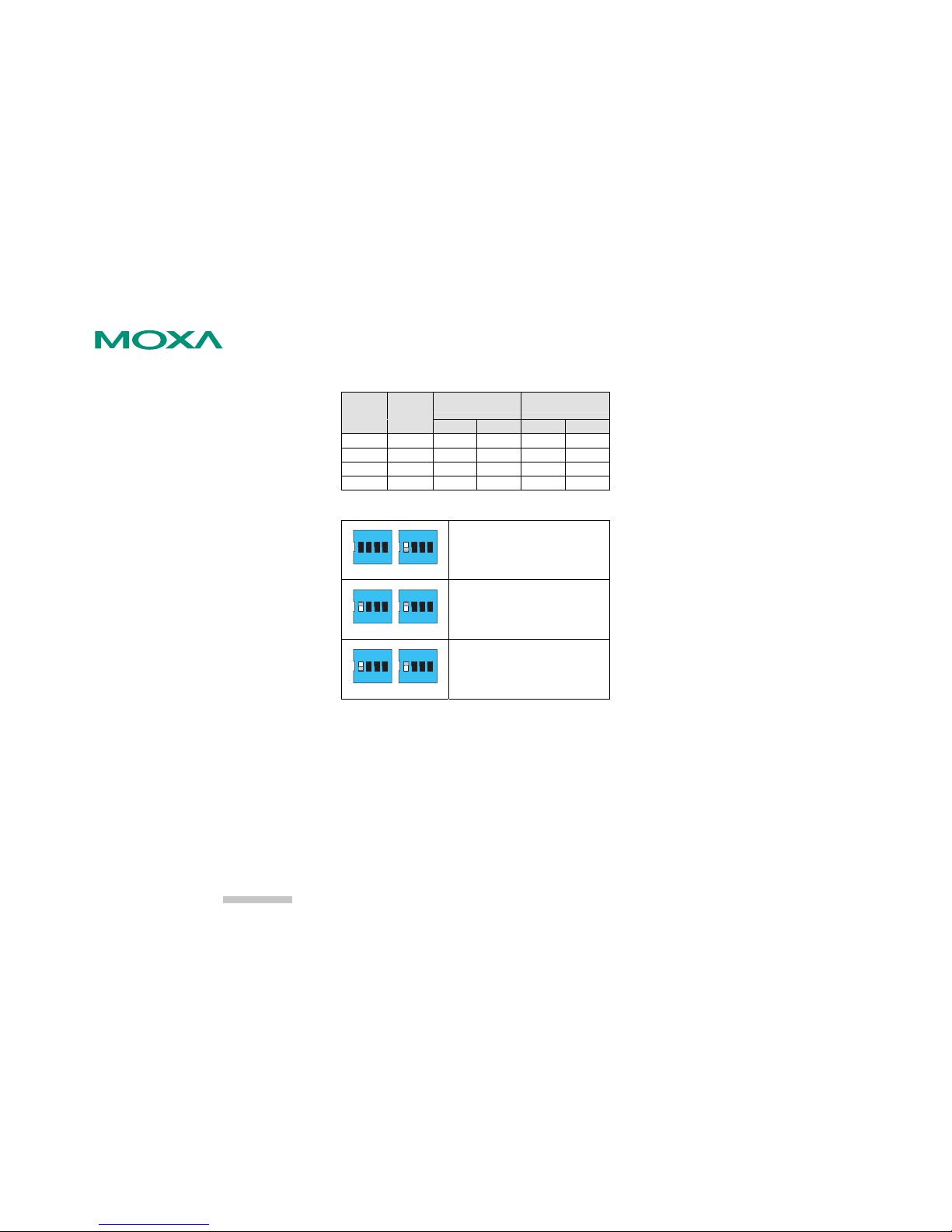
Jumper and DIP Switch Settings
Serial
Interface
Jumper
Placement
Ports 1 and 2 Ports 3 and 4
S1 S2 S1 S2
RS-232 on right N/A N/A --- ---
RS-422 on left N/A OFF N/A OFF
2w RS-485
on left ON ON ON ON
4w RS-485
on left OFF ON OFF ON
NOTE: N/A = Not Active. Ports 3 and 4 do not support RS-232.
The following figures illustrate the DIP switch settings for Port 1.
S2
2-WIRE
4-WIRE
RS485
RS422
S1
21
ON DIP
2143 43
ON DIP
Port 1 set for RS-422 transmission.
S2
2-WIRE
4-WIRE
RS485
RS422
S1
21
ON DIP
2143 43
ON DIP
Port 1 set for 2-wire RS-485 transmission.
S2
2-WIRE
4-WIRE
RS485
RS422
S1
21
ON DIP
2143 43
ON DIP
Port 1 set for 4-wire RS-485 transmission.
4. Software Installation Information
The board MUST be plugged in before installing the driver. See the
previous section for instructions on how to install the board in your PC.
Refer to the CP-134U User’s Manual for detailed instructions on
installing the drivers for this board.
Windows 2003/XP Driver Installation
1. After powering on your PC, Windows 2003/XP will automatically
detect the CP-134U V2 board.
2. Insert the CP-134U V2 software CD in your CD-ROM drive.
3. Select Install fro m a list or specific location (Advanced).
4. After selecting Sea rch for the best driver in these locations, check
the Include this location in the search checkbox, and then use the
browse button to navigate to the CD’s
CP-134U v2\Software\Win2K-XP-2003 folder.
5. Click on Continue Anyw ay in response to any warnings that the
software hasn’t passed Windows Logo testing.
6. After the board has been installed, the installation wiza rd will guide
you through the port installation procedure, starting with port 0.
7. If the board appears to be installed incorrectly, use the Device
Manager to check the installation of the board and ports. Click on the
+ sign next to Hardware, and then check under Multi-port serial
adapters and Ports (COM & LPT). If there are no warning marks,
such as a question mark or exclamation point in front of the board or
port icons, examine the Event Log to determine what the problem is.
Windows 2000 Driver Installation
1. After powering on your PC, Windows 2000 will automatically detect
the CP-134U V2 board.
2. Insert the CP-134U V2 software CD in your CD-ROM drive.
3. Select Search for a suitable driver for my device (recommended).
4. In Optional search location, checkmark specify a location. Navigate
to the \CP-134U V2\Software\Win2K-XP-2003 folder on the
software CD, and then click on OK to continue.
5. Click on Continue Anyw ay in response to any warnings that the
software hasn’t passed Windows Logo testing.
6. After the board has been installed, the installation wiza rd will guide
you through the port installation procedure, starting with port 0.
7. If the board appears to be installed incorrectly, use the Device
Manager to check the installation of the board and ports. Click on the
+ sign next to Hardware, and then check under Multi-port serial
adapters and Ports (COM & LPT). If there are no warning marks,
such as a question mark or exclamation point in front of the board or
port icons, examine the Event Log to determine what the problem is.
Windows 95/98 Driver Installation
1. After powering on your PC, Windows 95/98 will auto matically detect
the CP-134U V2 board.
2. Insert the CP-134U V2 software CD in your CD-ROM drive.
3. There are so me differences between the installation procedures for
Windows 95 and Windows 98. However, in both cases, be sure to
install the driver from the CD’s
CP-134U v2\Software\Win9x\Windows.95 folder.
4. After the board has been installed, the installation wiza rd will open
the port configuration window.
NOTE: If an error message similar to “CP-134U board (BusNo=x,
DevNo=x, Port1=COMx) interrupt number is invalid!” pops up, refer
to the “Troubleshooting” chapter of the User’s Manual for
information on how to handle this error.
P/N: 18020013401
Page 2
— 4 — — 5 — — 6 —
Windows NT Driver Installation
1. After powering on your PC, log into NT as Administrator.
2. Copy the folder CP-134U v2\Software\WinNT\Windows.nt to your
hard drive.
3. Open the Control Panel, click on the Netw ork icon, and select the
Adaptors tab.
4. Click the Add button, and then Have Disk… in the Select Network
Adapter window.
5. Specify the exact path to the f older created in Step 2 above.
6. Select MO XA Smartio/Industio Family multiport board in the
Select OEM Option window, and then click on OK to start installing
the driver.
7. When the Moxa Smartio/Industio Configuration Panel dialog box
appears, click on Add to open the Property window to modify port
settings and advanced FIFO configuration done automatically by the
system.
Linux Driver Installation
1. Execute the following commands from the Linux prompt:
#mount /dev/cdrom /mnt/cdrom
#cd /
#mkdir moxa
#cd moxa
#cp /mnt/cdrom/<driver directory>/mxser.tgz .
#tar xvfz mxser.tgz
2. #cd mxser
#make clean; make install
3. #cd /moxa/mxser/driver
#./msmknod
4. #modprobe mxser
5. Use the Moxa diag nostic utility to verify the driver status:
#cd /moxa/mxser/utility/diag
#./msdiag
6. Use the Moxa terminal utilit y to test the tty ports:
#cd /moxa/mxser/utility/term
#./msterm
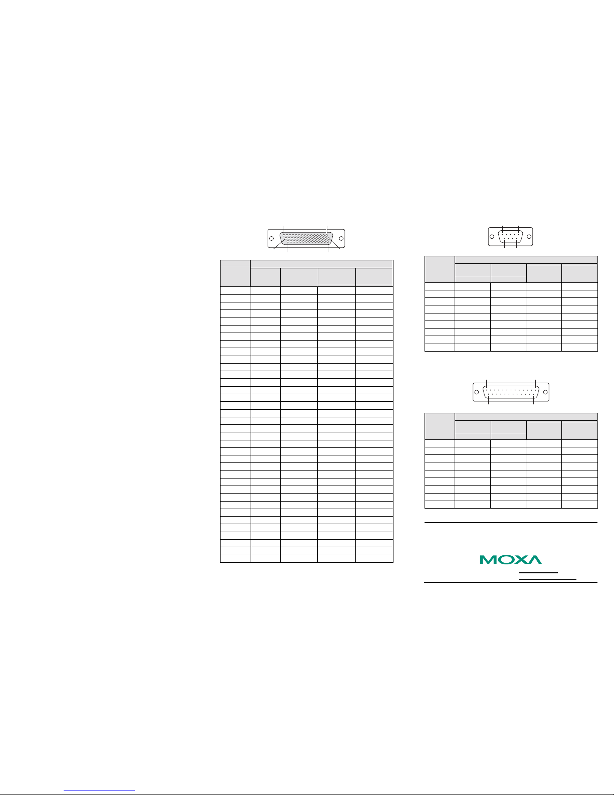
5. Pin Assignments
The CP-134U V2 boards have a female DB44 connector on the board.
In this section, we give the on-board connector’s pin assignments to
facilitate making your own connection cable, and the male DB9 and
male DB25 device-side pin assignments for the optional
CBL-M44M9x4-50 and CBL-M44M25x4-50 cables.
Female DB44 Connector: Board-side Pin Assignments
115
44 31
1630
Pin
Number
Transmission Signals
RS-232 RS-422
4-wire
RS-485
2-wire
RS-485
1 P4: RxD+(B) P4: RxD+(B) P4: Data+(B)
2 P4: TxD+(B) P4: TxD+(B)
3 P4: RTS+(B)
5 P3: RxD+(B) P3: RxD+(B) P3: Data+(B)
6 P3: TxD+(B) P3: TxD+(B)
7 P3: RTS+(B)
9 P2: TxD P2: RxD+(B) P2: RxD+(B) P2: Data+(B)
10 P2: RxD P2: TxD+(B) P2: TxD+(B)
11 P2: RTS P2: RTS+(B)
13 P1: TxD P1: RxD+(B) P1: RxD+(B) P1: Data+(B)
14 P1: RxD P1: TxD+(B) P1: TxD+(B)
15 P1: RTS P1: RTS+(B)
16 P4: CTS+(B)
17 P4: RxD-(A) P4: RxD-(A) P4: Data-(A)
18 P4: RTS-(A)
20 P3: CTS+(B)
21 P3: RxD-(A) P3: RxD-(A) P4: Data-(A)
22 P3: RTS-(A)
24 P2: CTS P2: CTS+(B)
25 P2: DTR P2: RxD-(A) P2: RxD-(A) P4: Data-(A)
26 P2: DSR P2: RTS-(A)
28 P1: CTS P1: CTS+(B)
29 P1: DTR P1: RxD-(A) P1: RxD-(A) P4: Data-(A)
30 P1: DSR P1: RTS-(A)
31 P4: TxD-(A) P4: TxD-(A)
32 P4: CTS-(A)
33 P4: GND P4: GND
35 P3: TxD-(A) P3: TxD-(A)
36 P3: CTS-(A)
37 P3: GND P3: GND
39 P2: DCD P2: TxD-(A) P2: TxD-(A)
40 P2: CTS-(A)
41 P2: GND P2: GND P2: GND
42 P1: DCD P1: TxD-(A) P1: TxD-(A)
43 P1: CTS-(A)
44 P1: GND P1: GND P1: GND
Male DB9 Connector: Device-side Pin Assignments
15
69
Pin
Number
Transmission Signals
RS-232 RS-422
4-wire
RS-485
2-wire
RS-485
1 DCD TxD-(A) TxD-(A) --2 RxD TxD+(B) TxD+(B) --3 TxD RxD+(B) RxD+(B) Data+(B)
4 DTR RxD-(A) RxD-(A) Data-(A)
5 GND GND GND GND
6 DSR RTS-(A) --- --7 RTS RTS+(B) --- --8 CTS CTS+(B) --- --9 --- CTS-(A) --- ---
Male DB25 Connector: Device-side Pin Assignments
1 13
14 25
Pin
Number
Transmission Signals
RS-232 RS-422
4-wire
RS-485
2-wire
RS-485
2 TxD TxD+(B) TxD+(B) --3 RxD RxD+(B) RxD+(B) Data+(B)
4 RTS RTS+(B) --- --5 CTS CTS+(B) --- --6 DSR RTS-(A) --- --7 GND GND GND GND
8 DCD RxD-(A) RxD-(A) Data-(A)
20 DTR TxD-(A) TxD-(A ) --22 --- CTS-(A) --- ---
Copyright 2004
Moxa Technologies Co., Ltd.
All rights reserved.
Reproduction without permission is prohibited.
Tel: +886-2-8919-1230 www.moxa.com
Fax: +886-2-8919-1231 support@moxa.com.tw
Page 3

— 4 — — 5 — — 6 —
 Loading...