

Page 1

Industio CP-134U Series
User’s Manual
Industrial 4-Port RS-422/485 Serial Board for PCI Bus
www.moxa.com/product
Fifth Edition, January 2004
This manual is also available on CD-ROM and at Moxa’s Website
Moxa Technologies Co., Ltd.
Tel: +886-2-8919-1230
Fax: +886-2-8919-1231
www.moxa.com
support@moxa.com.tw (Worldwide)
support@moxa.com (The Americas)
Page 2

Industio CP-134U Series User’s Manual
The software described in this manual is furnished under a license agreement and may be used only in
accordance with the terms of that agreement.
Copyright Notice
Copyright 2004 Moxa Technologies Co., Ltd.
All rights reserved.
Reproduction without permission is prohibited.
Trademarks
MOXA is a registered trademark of Moxa Technologies Co., Ltd.
All other trademarks or registered marks in this manual belong to their respective manufacturers.
Disclaimer
Information in this document is subject to change without notice and does not represent a commitment on
the part of Moxa.
Moxa provides this document “as is,” without warranty of any kind, either expressed or implied,
including, but not limited to, its particular purpose. Moxa reserves the right to make improvements and/or
changes to this manual, or to the products and/or the programs described in this manual, at any time.
Information provided in this manual is intended to be accurate and reliable. However, Moxa Technologies
assumes no responsibility for its use, or for any infringements on the rights of third parties that may result
from its use.
This product might include unintentional technical or typographical errors. Changes are periodically
made to the information herein to correct such errors, and these changes are incorporated into new
editions of the publication.
Page 3

MOXA Internet Services
Customer satisfaction is our number one concern, and to ensure that customers receive the
full benefit of our products, Moxa Internet Services has been set up to provide technical
support, driver updates, product information, and user’s manual updates.
The following services are provided
E-mail for technical support................................support@moxa.com.tw
World Wide Web (WWW) Site for product information:
.............................http://www.moxa.com
.............................http://www.moxa.com.tw
or
Page 4

Table of Contents
1 Introduction ........................................................................... 1-1
Overview .......................................................................................................1-2
Features .........................................................................................................1-4
Package Checklist .........................................................................................1-4
2 Hardware Installation ............................................................ 2-1
CP-134U Series Block Diagrams .................................................................. 2-2
Installing the Industio CP-134U Series Board.............................................. 2-7
3 Software Installation ............................................................. 3-1
Windows NT ................................................................................................. 3-2
Windows 95/98............................................................................................3-10
Windows 2000/XP.......................................................................................3-25
Linux ...........................................................................................................3-37
4 Serial Programming Tools.................................................... 4-1
PComm Installation .........................................................................................4-2
PComm Programming Library ........................................................................ 4-2
RS-485 Programming.................................................................................... 4-2
5 Connection Cables and Cable Wiring.................................. 5-1
Pinouts and Cable Wiring..............................................................................5-1
Impedance Matching and Termination Resistors .......................................... 5-9
6 Troubleshooting .................................................................... 6-1
General Troubleshooting............................................................................... 6-1
Windows NT ................................................................................................. 6-3
Windows 95/98..............................................................................................6-4
A Technical Reference .............................................................A-1
Specifications ............................................................................................... A-1
PCI................................................................................................................ A-2
Return Procedure.......................................................................................... A-3
Revision History........................................................................................... A-4
Page 5

1
1
1 Introduction
Welcome to the MOXA CP-134U Series of industrial 4-port RS-422/485 serial boards for
the PCI bus.
The following topics are covered in this chapter:
Overview
Features
Package Checklist
Page 6

Overview
Industio—The Industrial Multiport Async Solution
Moxa Industio products are smart, multiport serial I/O solutions for industrial applications.
The Industio CP-134U Series boards, including CP134-UI and CP-134UL, are designed
for a 32-bit PCI bus with the Plug and Play and Universal PCI feature. The ports for these
boards can be configured independently, with ports 1 and 2 set to the RS-232, RS-422, or
RS-485 interface, and ports 3 and 4 set to the RS-422 or RS-485 interface. Industio
products provide a reliable communication link over a longer distance (up to 4000 ft for
ports set to the RS-422/485 interface), and are suitable for industrial environments.
Connections with point-to-point full-duplex (RS-422 or 4-wire RS-485)or multidrop
half-duplex (2-wire RS-485) are available to meet user’s various needs. And each RS-485
port can control up to 32 devices in a multidrop environment.
ADDC™ (Automatic Data Direction Control) for RS-485
To make it easier to manage 2-wire RS-485 half-duplex connections, ADDC™ (Automatic
Data Direction Control) intelligence is built into each CP-134U series board, eliminating
the need for software interference. This means that Windows applications can manage
RS-485 ports without needing to write extra code for controlling the half-duplex protocol.
With their well-designed and fine-tuned device driver, Industio CP-134U boards make full
use of the 64 byte Tx/Rx FIFO and on-chip H/W flow control, so that they can transfer data
without loss even at speeds as high as 230.4 Kbps, providing a reliable, high performance
solution for serial multiport communications.
Termination Resistors Ready for RS-422/485
Termination Resistors are already installed on the Industio CP-134U series boards,
eliminating the headaches involved in determining the proper impedance for the resistors.
For more details, refer to the “Connection Cable and Cable Wiring” chapter.
Surge/Isolation Protection
To prevent boards from being damaged by lightning or high potential voltage, TVSS
(Transient Voltage Surge Suppressor) technology is included in some models to protect the
board. An optical isolation option (2000V), and embedded surge protection (max. ESD of
16 KV, max. EFT of 2 KV) are also available in this series. Both of these features provide
protection when the boards are used in critical or harsh factory-type environments.
PCI Solution
The board complies with PCI Spec. 2.1 and does not require either switches or jumpers.
The hardware configuration for the IRQ and I/O address is automatically assigned by the
1-2
Industio CP-134U Series User’s Manual
Page 7

Introduction
PCI BIOS. This means that the board MUST be plugged into the computer first before
installing the driver software. For more PCI information, refer to the Technical Reference
Appendix.
Universal PCI
The 32/64-bit PCI local bus specification specifies both 3.3V and 5V connector types for
the PCI hardware. Moxa’s universal PCI card allows the user to plug into both a 3.3V and
32/64-bit slot.
Operating System Support
The Industio CP-134U series is compatible with most major industrial platforms, including
Windows NT/2000/XP, Windows 95/98, and Linux. MOXA device drivers are provided
for smoother installation, configuration, and performance. In this manual, sections for
MOXA Windows NT, Windows 2000/XP, Windows 95/98, and Linux are included.
MOXA Serial Comm Tools
For application development, MOXA provides an easy-to-use serial communication library
called PComm that runs under Windows NT/2000/XP and Windows 95/98. You can use this
library to develop your own applications using Visual Basic, Visual C++, Borland Delphi,
etc. Utilities, such as Data Scope, Monitor, Terminal Emulator, Diagnostics, etc., are
included for debugging or monitoring the communication status, terminal emulation, or
even file transfer.
Board Applications
The board is suitable for many industrial applications, including:
Multipoint data acquisition
Factory automation
Critical industrial control
Remote serial device control
Industio CP-134U Series User’s Manual
1-3
Page 8

Features
The Industio CP-134U Series includes the following products:
CP-134U 4 RS-422/485 ports, Universal PCI interface with embedded Surge
Protection and Isolation Protection (16 KV ESD, 2 KV Isolation)
CP-134UI 4 RS-422/485 ports, Universal PCI interface with embedded Surge
Protection and Isolation Protection
Below we list the outstanding features of the Industio CP-134U Series boards:
Supports 4 independent serial ports—2 ports for RS-232 or RS-422/485, and 2 ports
Compact board size (half-size)
Jumpers for selecting between RS-232 and RS-422/485
DIP Switches for selecting between RS-422, 4-wire RS-485, and 2-wire RS-485
DIP Switch for RS-485 data control—ADDC™ (Automatic Data Direction Control)
Jumper for Termination Resistor selection—eliminates impedance matching headaches
Reliability—high speed 16C550C compatible Communication Controllers with
PComm Lite—a powerful serial Comm utility.
Embedded Surge Protection (16 KV ESDS) for all signal lines (CP-134UI, CP-134UL)
Supports 64 byte FiFo Driver
Supports drivers for most major industrial platforms—Windows NT/2000/XP,
Supports both 3.3V and 5V connector types
for RS-422/485
on-chip hardware flow control to guarantee no data loss
Windows 95/98, and Linux
Package Checklist
You should find the following items in the Industio CP-134U Series package:
Industio CP-134U Series 4-port serial board
MOXA software CD-ROM, which includes:
Drivers for MOXA Multiport Async Products
User’s Manual (PDF format)
1-4
Industio CP-134U Series User’s Manual
Page 9

2
2
2 Hardware Installation
You will need to install both hardware and software for Industio CP-134U Series boards.
The hardware installation procedure is given in this chapter, and the next chapter deals with
software installation for various operating systems. The following topics are covered in this
chapter:
CP-134 Series Block Diagram
Installing the Industio CP-134U Series Board
Page 10
CP-134U Series Block Diagrams
Industio CP-134U Series boards’ hardware configuration for IRQ number and I/O address
is automatically assigned by the PCI BIOS. This means that the board MUST be plugged in
first before installing the driver software.
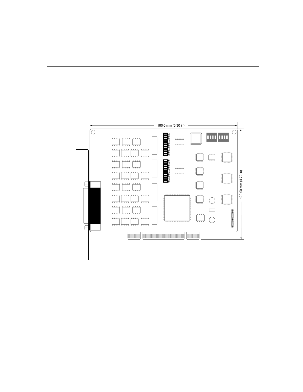
CP-134UI
2-2
Industio CP-134U Series User’s Manual
Page 11
Hardware Installation
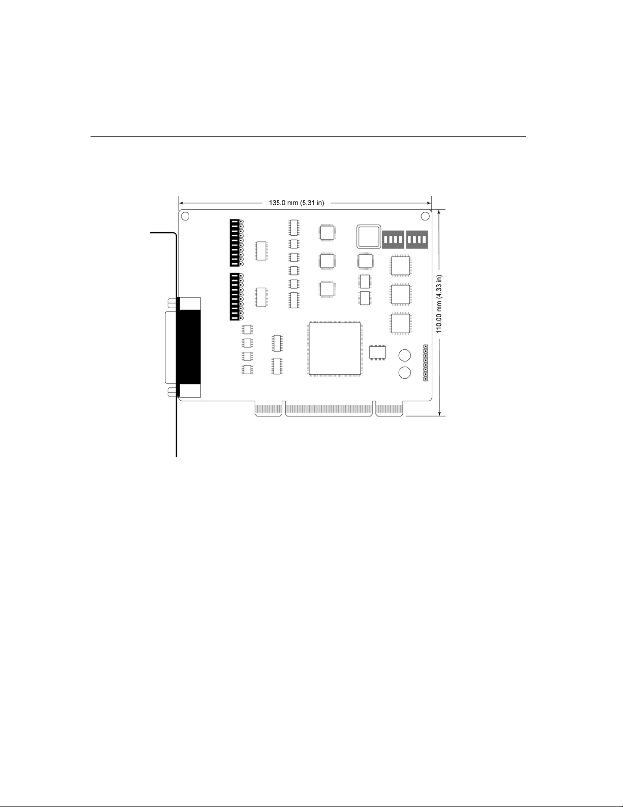
CP-134U
The Industio CP-134U Series has two 30-pin jumpers and two sets of four DIP Switches
on the board that allow the user to set the serial interface for each of the board’s four ports.
Ports 1 and 2 can be set to RS-232, RS-422, RS-485 (2-wire), or RS-485 (4-wire). Ports 3
and 4 can be set to RS-422, RS-485 (2-wire), or RS-485 (4-wire). Refer to the following
information to determine the proper settings for your board.
Industio CP-134U Series User’s Manual
2-3
Page 12
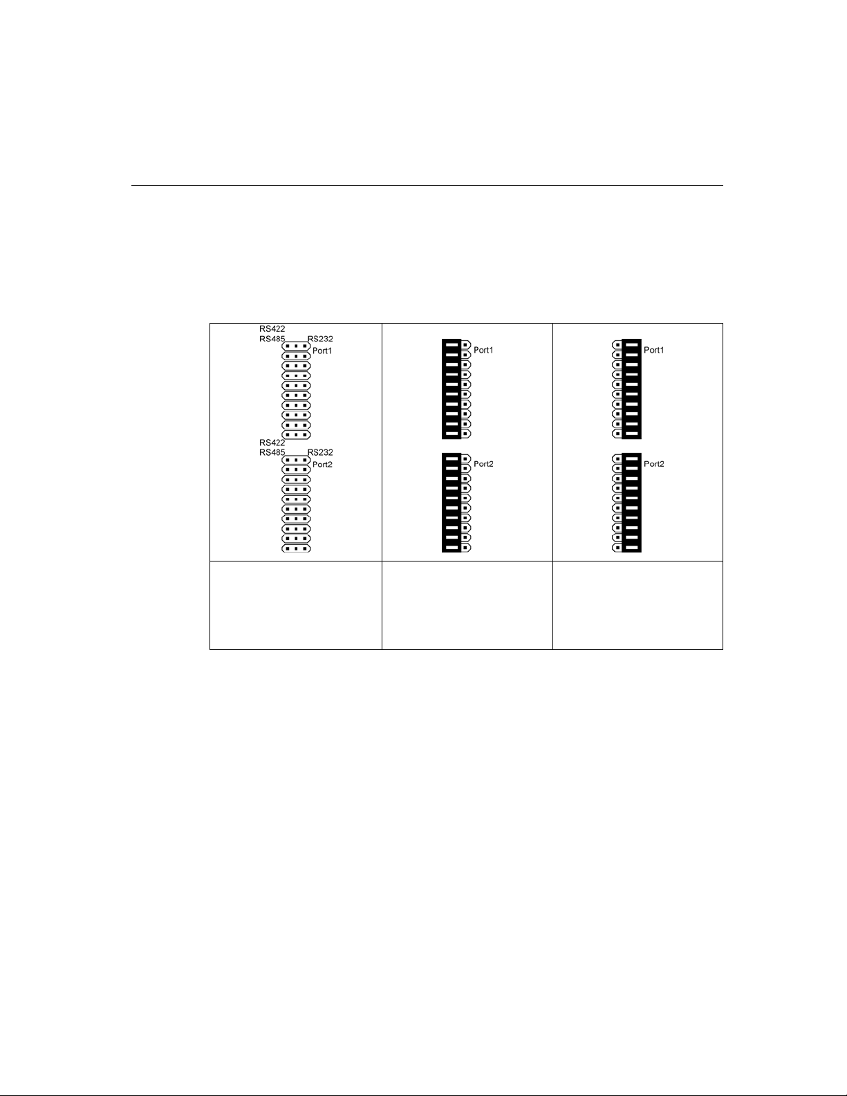
Jumper Settings
The two on-board 30-pin jumpers are used to select between the RS-232 and RS-422/485
serial interfaces. If you select RS-422/485, then you will also need to set the DIP Switches
to select between RS-422, RS-485 (4-wire), and RS-485 (2-wire). Note that the two ports
can be configured independently.
Jumper pins:
Top for Port 1,
Bottom for Port 2
RS-422/485:
Cover the left two
columns of pins with the
jumper to select the
RS-422/485 option.
RS-232:
Cover the right two
columns of pins with the
jumper to select the RS-232
option.
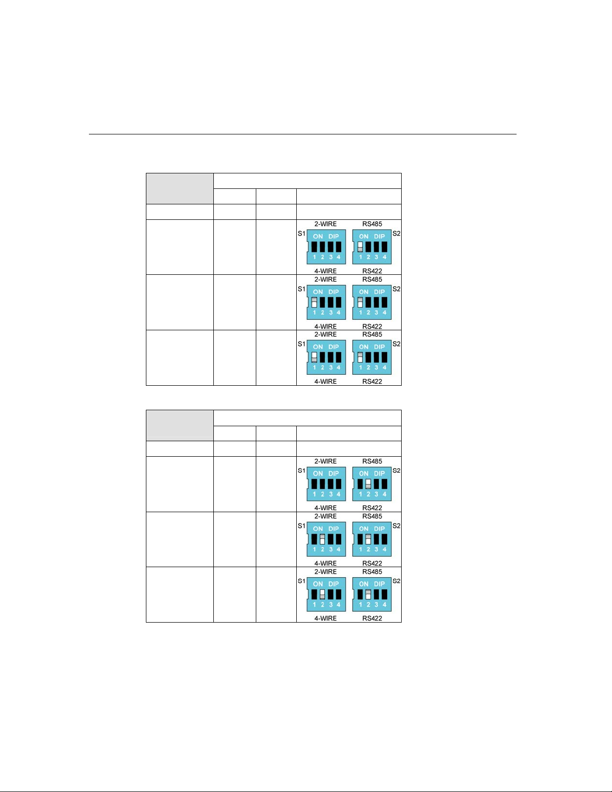
DIP Switch Settings
Refer to the figures on the following two pages to see how to select between RS-422,
RS-485 (2-wire), and RS-485 (4-wire).
2-4
Industio CP-134U Series User’s Manual
Page 13
Hardware Installation
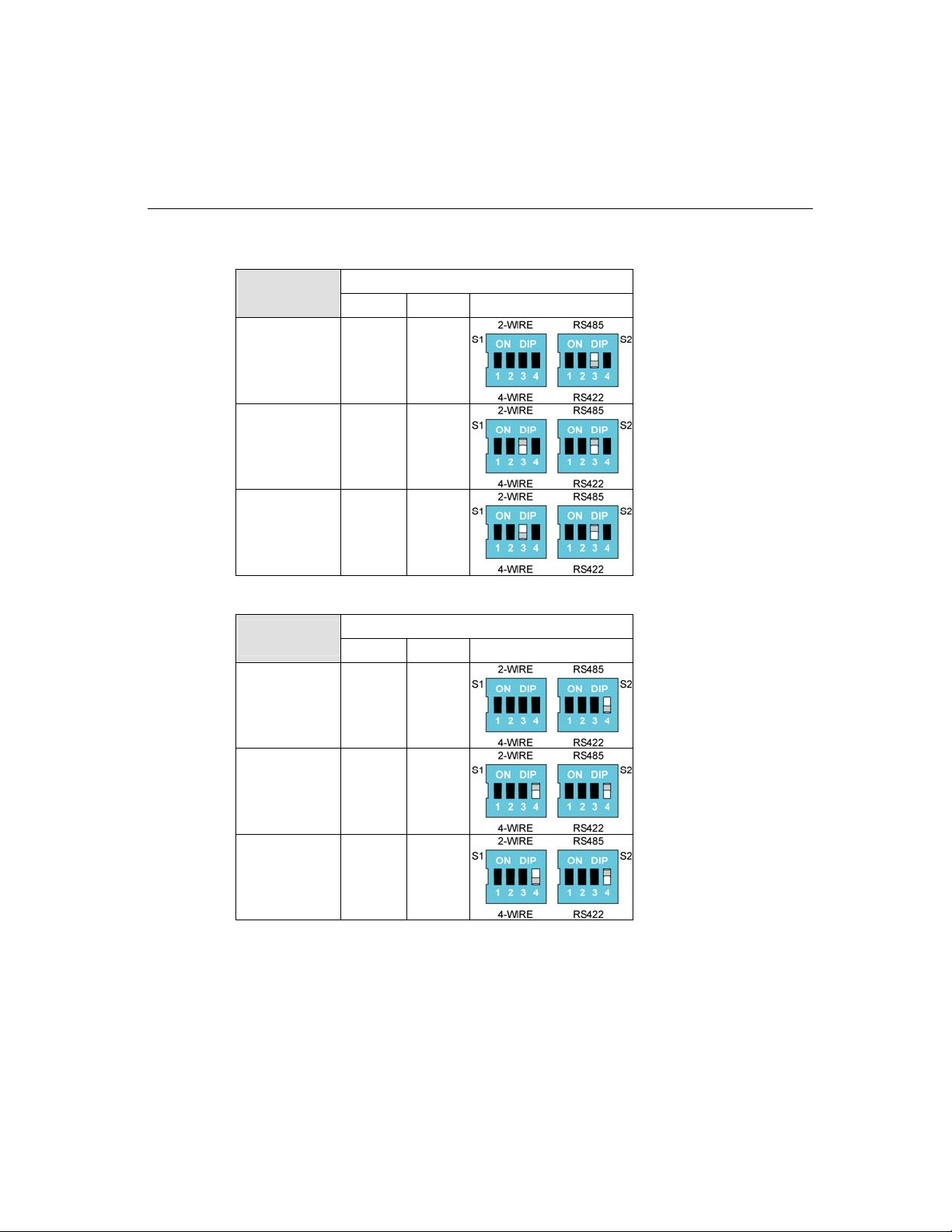
DIP Switch
Settings
RS-232 — —
RS-422 — OFF
S1-1 S2-1
Port 1
RS-485
(2-wire)
RS-485
(4-wire)
ON ON
OFF ON
DIP Switch
Settings
RS-232 — —
RS-422 — OFF
RS-485
(2-wire)
S1-2 S2-2
ON ON
Port 2
RS-485
(4-wire)
OFF ON
Industio CP-134U Series User’s Manual
2-5
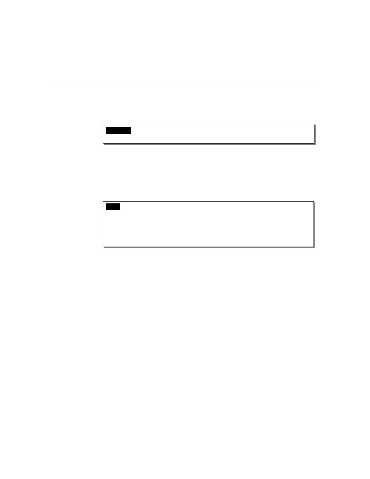
Page 14
DIP Switch
Settings
RS-422 — OFF
S1-3 S2-3
Port 3
RS-485
(2-wire)
RS-485
(4-wire)
ON ON
OFF ON
DIP Switch
Settings
RS-422 — OFF
RS-485
(2-wire)
RS-485
(4-wire)
S1-4 S2-4
ON ON
OFF ON
Port 4
2-6
Industio CP-134U Series User’s Manual
Page 15
Hardware Installation
Installing the Industio CP-134U Series Board
Step 1 : Power off the PC.
Warnin g! To avoid damaging your system and board, make sure your computer is
turned off before installing any board.
Step 2: Remove the PC’s cover.
Step 3: Remove the slot cover bracket if there is one.
Step 4: Plug the Industio CP-134U Series control board firmly into a free 32-bit PCI slot,
or the CP-134U Series board into both a 32-bit/64-bit slot.
Step 5: Fasten the holding screw to fix the control board in place.
Step 6: Replace the system cover.
Step 7: Power on the PC. The BIOS will automatically set the IRQ and I/O address.
Note! Each board must occupy one unique IRQ and two 8-byte I/O addresses,
which are assigned automatically by the PCI BIOS. However, you can
select a free IRQ number manually via the PC’s BIOS setup for the PCI slot,
but normally this method is not available for the I/O address. The possible
IRQ numbers are 2, 3, 4, 5, 7, 10, 11, 12, and 15. The possible I/O addresses
are from 0x0000 to 0xFFFF.
Step 8: Proceed with the software installation discussed in the next chapter, “Software
Installation.”
Industio CP-134U Series User’s Manual
2-7
Page 16

Page 17

3
3
3 Software Installation
In this chapter, the software driver installation, configuration, and driver update/removal
procedures are described for various operating systems, including Windows NT, Windows
95/98, Windows 2000/XP, and Linux. Before proceeding with the software installation,
complete the hardware installation, discussed in the previous chapter, “Hardware
Installation.”
If you need to develop your own applications, refer to the next chapter, “Serial
Programming Tools,” for programming issues.
The following topics are covered in this chapter:
Windows NT
Windows 95/98
Windows 2000/XP
Linux
Page 18

Windows NT
Windows NT supports up to 256 serial ports, from COM1 to COM256. To fully integrate
the advanced features of Windows NT, Moxa has developed multi-process and multi-thread,
pure 32-bit Windows NT device drivers for the Industio CP-134U Series multiport boards.
The driver conforms to the Win32 COMM API standard.
To install the driver for the first time, go directly to the next section, “Installing the
Driver.”
If the driver is already installed, and you want to re-configure the board and port(s),
add more boards, or delete boards, refer to the section “Configuring the Board and
Ports.”
To update or remove the driver, refer to either, “Updating the Driver” or “Removing
the Driver.”
3-2
Industio CP-134U Series User’s Manual
Page 19
Installing the Driver
The following procedure is for installing the Industio CP-134U Series driver for the first
time under Windows NT 4.0. Before taking these steps, make sure the board(s) have
already been plugged into the system’s PCI slot(s).
1. Log into NT as Administrator.
2. Open the [Control Panel], click on the [Network] icon, and select the [Adapters] tab.
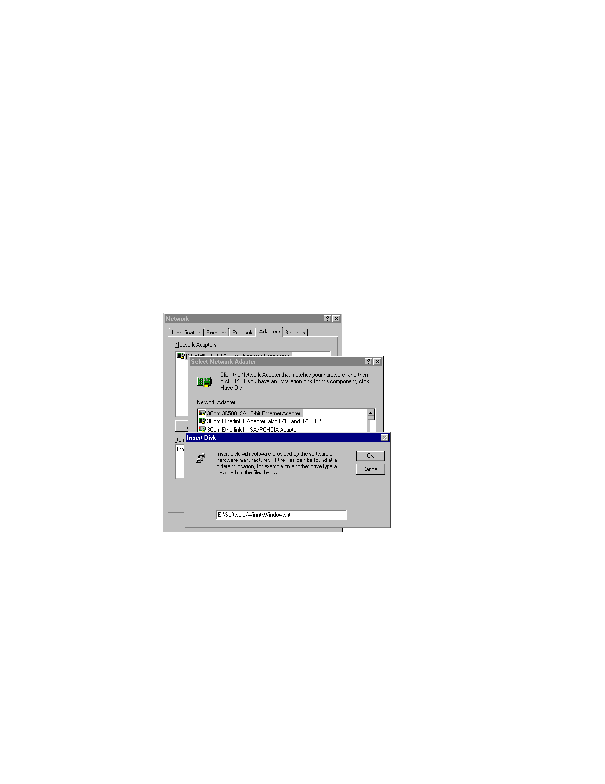
3. Click on the [Add] button, then the [Have Disk...] button in the “Select Network
Adapter” dialog box.
4. Specify the exact path of the driver diskette, E:\Software\Winnt\Windows.nt for the
example shown here, and then click [OK].
Software Installation
Industio CP-134U Series User’s Manual
3-3
Page 20
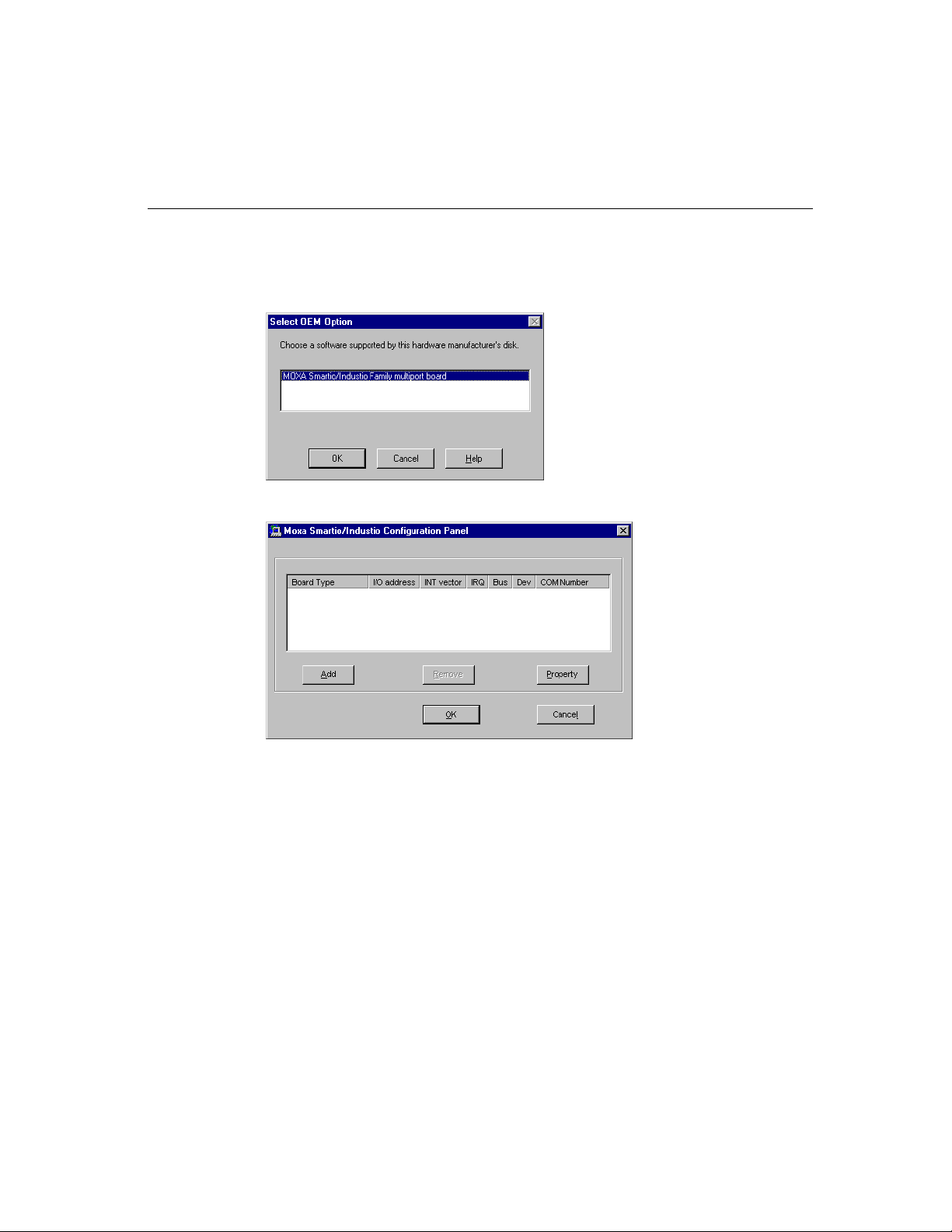
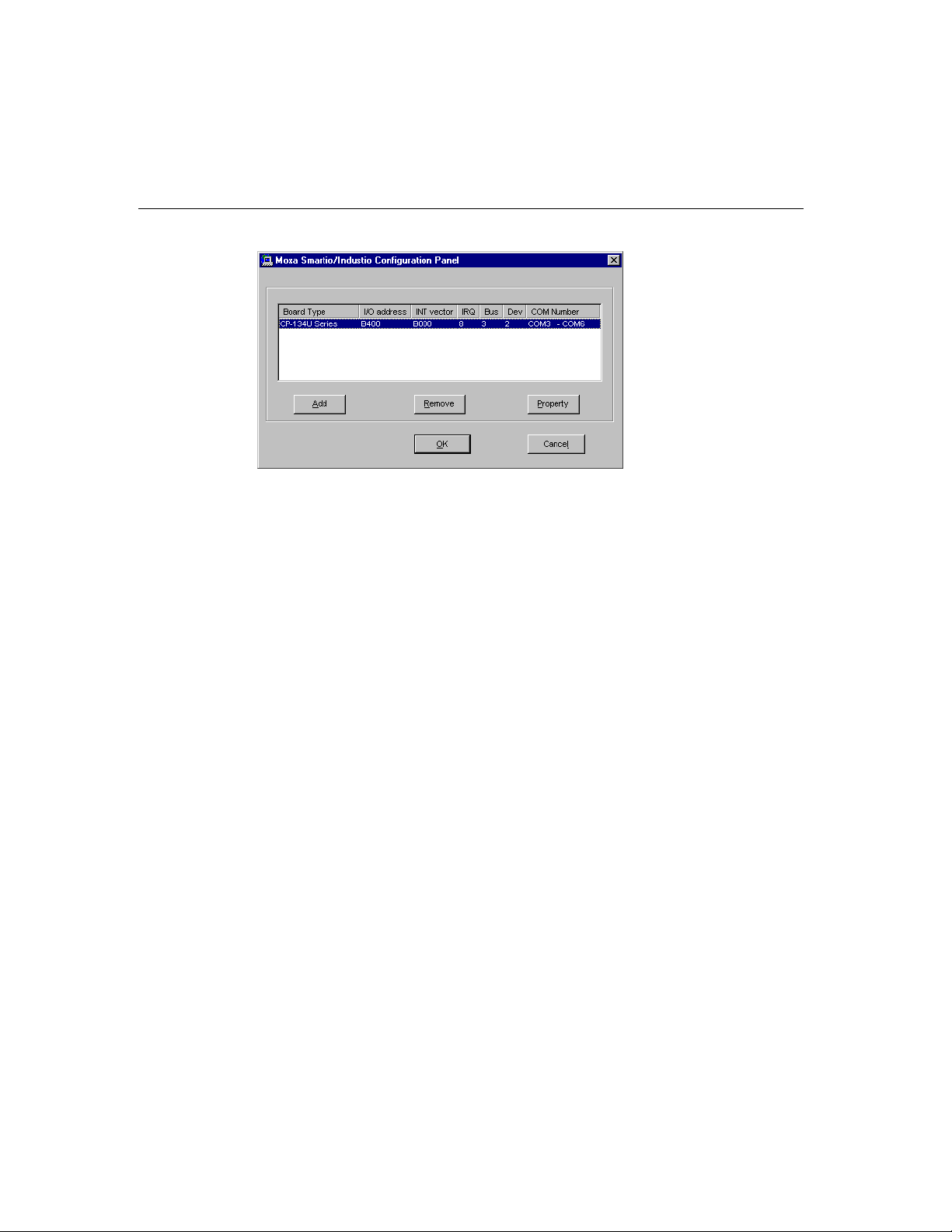
5. Select “MOXA Smartio/Industio Family multiport board” from the “Select OEM
Option” dialog box, and then click [OK] to enter the “MOXA Smartio/Industio
Configuration Panel” dialog box to start the installation.
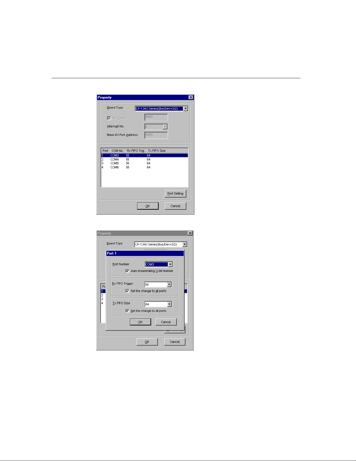
6. Click the [Add] button to open the Property dialog box to change port settings and
advanced FIFO configurations done automatically by the system.
3-4
7. In the “Property” dialog box, select the newly plugged Industio CP-134U Series
board from the Board Type pull down list. Next, click on one of the ports to highlight
it, and then click on [Port Setting] to open the port’s configuration window.
Industio CP-134U Series User’s Manual
Page 21
Software Installation
8. The [Port #] window will open to allow you to change settings, as described below, for
that particular port.
Port Number
You must set up all of the board’s ports with the desired “COM number,” which
Industio CP-134U Series User’s Manual
3-5
Page 22
should not conflict with other COM numbers in use. In this “Individual Port Setting”
dialog box, there are two ways to map physical ports to COM numbers, depending on
whether you check the “Auto Enumerating COM Number” box.
If “Auto Enumerating COM Number” is checked, and the COM number of the first
port is specified, then subsequent ports are mapped to the next available COM number.
For instance, if the first port is mapped to COM3, then the second port is mapped to
COM4.
If “Auto Enumerating COM Number” is not checked, specify the COM number for
each port separately. For example, the second port could be mapped to COM10, and
the first port mapped to COM3.
Rx FIFO Trigger
You may choose from Rx FIFO trigger levels of from 1 to 62 bytes, with the default
value set at 56 bytes.
Tx FIFO Size
You may choose a Tx FIFO size from between 1 and 64 bytes with the default value
set at 64 bytes.
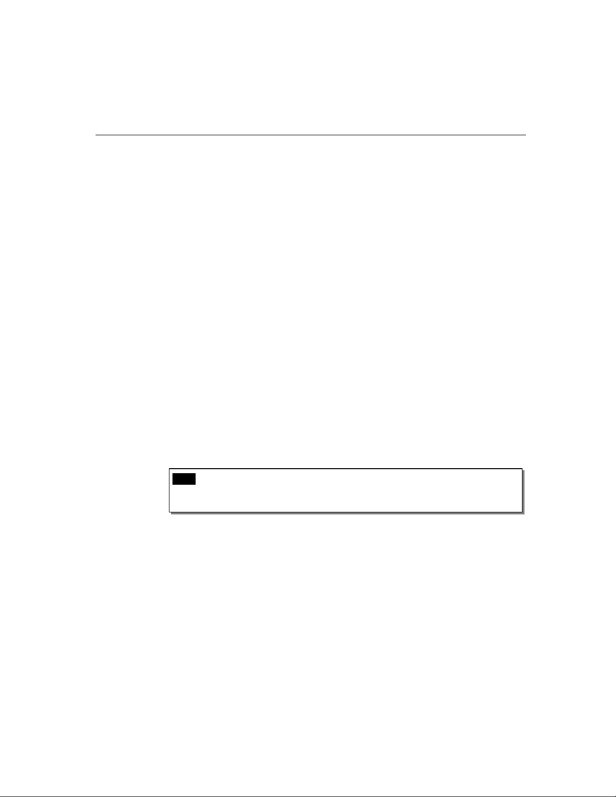
9. Click [OK] in the “Port #” and “Property” dialog boxes to go back to the “MOXA
Smartio/Industio Configuration Panel” dialog box.
3-6
Note ! If you need to install more than one board, click [Add] and repeat steps 6
to 8 to configure the additional board. Up to four Industio CP-134U Series boards
can be installed in one NT system.
Click [OK] to finish the configuration.
Industio CP-134U Series User’s Manual
Page 23
Software Installation
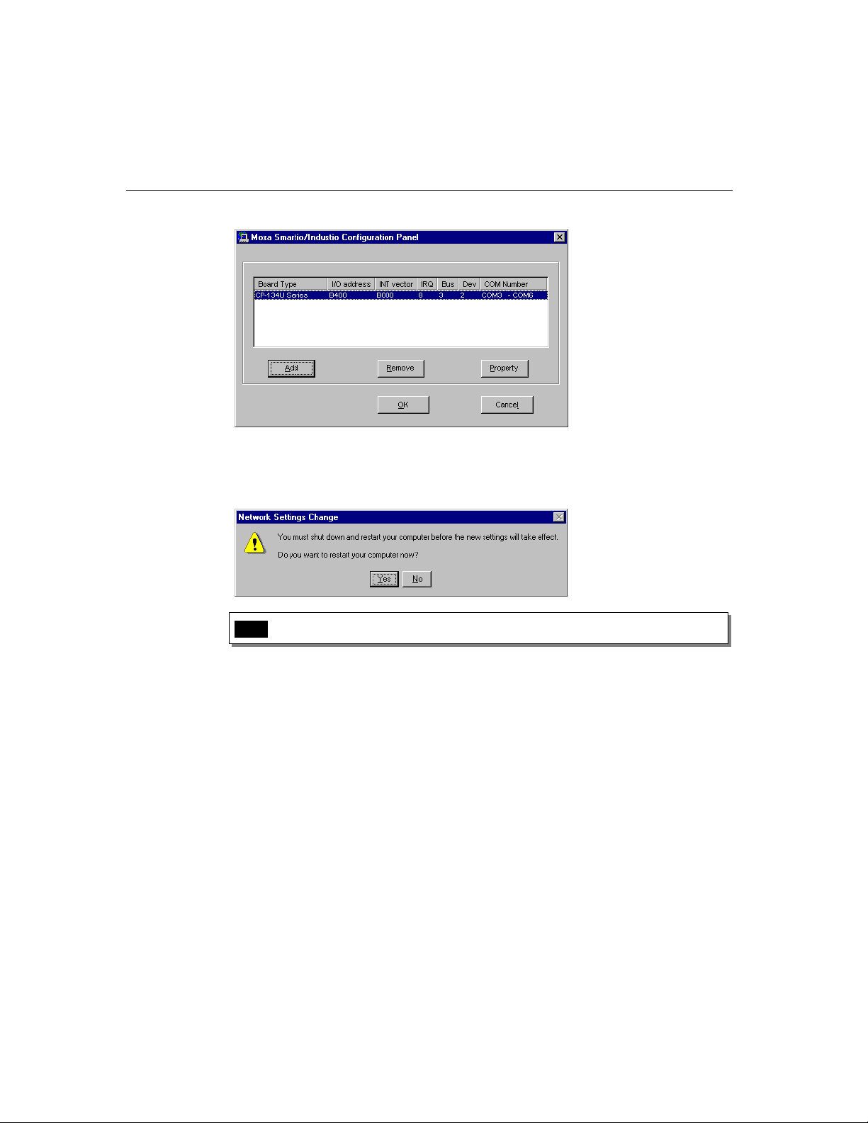
10. When you have finished the configuration, click on the [Close] button in the “Network
Settings” dialog box.
11. Restart the Windows NT system. The new configuration will take effect when the
system restarts.
Note ! The latest configuration will not take effect unless the system restarts.
12. Once the system restarts, you may check the event log issued by the MOXA driver to
see if the board’s ports have been initialized successfully.
Enter the [Administrative] group, click on the [Event Viewer] icon and select
[System Event Log] to check a message similar to “MOXA CP-134U, with first
serial port COM3, has been enabled” for each configured board.
If an error message similar to “Cannot find any configured MOXA CP-134U
board!” appears, refer to the “Troubleshooting” chapter for solutions.
Industio CP-134U Series User’s Manual
3-7
Page 24
Note ! Once the board and the driver are installed and the driver restarts
successfully, you can start to develop applications with the PComm library (see the
“Serial Programming Tools” chapter) or the Microsoft Win32 API. You can also
execute ready-made applications, such as PComm utility Terminal emulator (see
“Serial Programming Tools” chapter) or HyperTerminal to transmit/receive data, as
well as Remote Access Service to provide dial-up networking capabilities.
Configuring the Board and Ports
The following steps explain how to re-configure the board’s ports:
1. In the [Control Panel], click on the [Network] icon and select the [Adapters] tab.
2. Select “MOXA Smartio/Industio Family Adapter” in “Network Adapters.”
3-8
3. Click on the [Properties] button to open the “MOXA Smartio/Industio
Configuration Panel” dialog box. See steps 8-9 in the previous section, “Installing the
Driver,” for more details.
Industio CP-134U Series User’s Manual
Page 25
Software Installation
You may use this configuration panel to:
Click on [Property] to enter the “Property” dialog box to configure the selected
board with the correct “COM Number,” “Rx FIFO Trigger,” and “Tx FIFO Size.”
See Steps 8 and 9 in the previous section, “Installing the Driver,” for more details.
Click on [Add] to add one more board that has not yet been configured for the
system. See Steps 6 to 9 in the previous section, “Installing the Driver,” for more
details.
To automatically remove the configuration, simply unplug the CP-134U Series
board—after you turn off your PC. There is no need to use the remove board
function from the Moxa Smartio/Industio Configuration Panel dialog box.
Click [OK] to confirm the configuration changes that you’ve made.
Click on [Cancel] to close the window without changing the configuration.
Updating the Driver
To update the driver for the Industio CP-134U Series board, simply remove the driver, as
described in the next section, and reinstall it as detailed in the section, “Installing the
Driver.”
Industio CP-134U Series User’s Manual
3-9
Page 26

Removing the Driver
To remove the driver for the Industio CP-134U Series board,
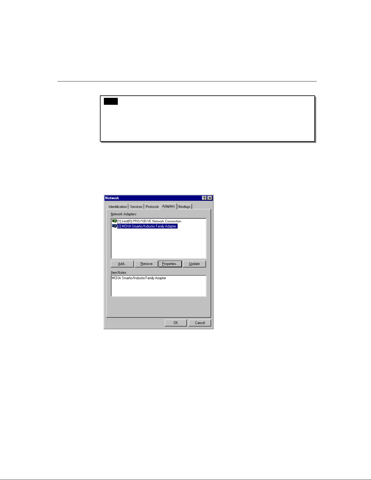
1. Open the [Control Panel], click on the [Network] icon, and select the [Adapters] tab.
2. Select “MOXA Smartio/Industio Family Adapter” from the adapter list, and then
click on the [Remove] button, and then click [OK] to remove the driver.
3. Restart the system to activate the new configuration.
Windows 95/98
Windows 95/98 supports up to 128 serial ports, from COM1 to COM128. To fully
integrate the advanced features of Windows 95/98, Moxa has developed multi-process and
multi-thread, pure 32-bit Windows 95/98 virtual device port drivers (VxD) compliant with
communication drivers (VCOMM), for the Industio CI-134 Series and other MOXA
multiport boards. The drivers conform to the Win32 COMM API standard.
To install the driver for the first time, go directly to the section, “Installing the Driver.”
If you have already installed the driver and want to re-configure the board and ports,
add more boards, or delete boards, refer to the section “Configuring the Board and
Ports.”
To upgrade or remove the driver, go to either the “Updating the Driver” or “Removing the
Driver” sections.
Installing the Driver
Because of Windows 95/98’s Plug and Play capability, you can easily plug in the Industio
CP-134U Series board and get to work right away with very little installation effort.
Windows 95/98 will automatically detect the presence of the newly plugged board and
prompt you to install the driver software from the driver diskette.
At most, 4 Industio CP-134U Series boards can be installed in ONE system, provided I/O
addresses and IRQ number resources are sufficient and available in the system.
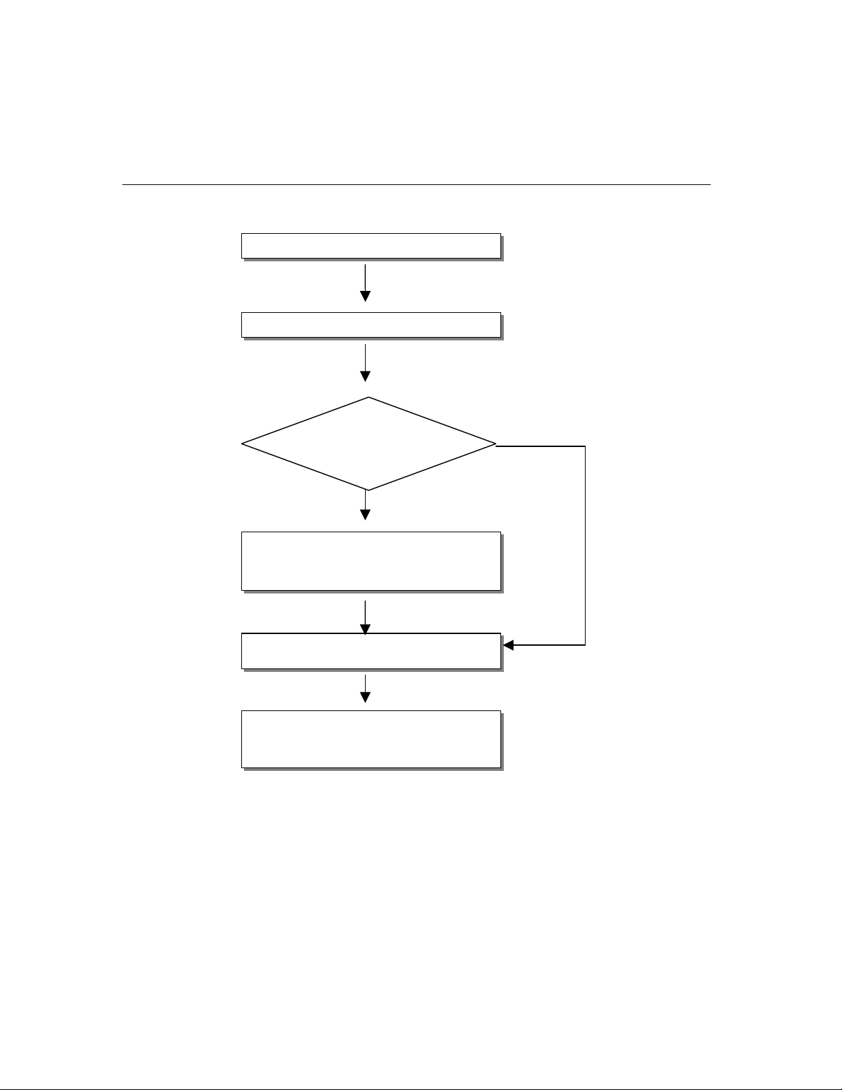
The following flow chart illustrates the driver installation stages of the Industio CP-134U
Series boards. Each stage will be discussed in turn.
3-10
Industio CP-134U Series User’s Manual
Page 27
Software Installation
Install the Smartio PCI board in the system.
Start Windows 95/98 to detect the board.
Driver installed before? Yes
No
Install the driver from the diskette.
See the “First Time Driver
Installation” section.
Configure the port.
See the “Port Configuration” section.
The Industio CP-134U Series ports should
now be ready for use.
See the “Board and Ports Ready” section.
Industio CP-134U Series User’s Manual
3-11
Page 28

First Time Driver Installation Stage
This stage presents the steps for installing the Industio CP-134U Series board driver for the
first time. The installation of the Industio CP-134U Series board for Windows 95 and
Windows 98 are slightly different and will be described in two columns. Follow the steps in
the left column for Windows 95, or the right column for Windows 98, respectively.
If a MOXA CP-134U Series board was already installed, and another MOXA CP-134U
Series board is plugged in, the system will prompt you to take care of Port Configuration
for the new board, and skip this stage.
1. After detecting the first new Industio CP-134U Series board, Windows 95/98 will
automatically display a [New hardware found] message box, and show the following
windows. Click on [Next] to continue.
Windows 95 Windows 98
2. Click on [Other Locations].
3-12
Industio CP-134U Series User’s Manual
2. Select [Display a list...] and then click on
[Next] to continue.
Page 29

Windows 95 Windows 98
3. Type A:\Windows.95 in the Location field, and
then click [OK] in the [Select Other Location]
window. The system will start reading the files
from the diskette.
Software Installation
3. Select Other Devices and then click [Next] to
continue.
4. Click on [Finish].
4. Click on [Have Disk].
Industio CP-134U Series User’s Manual
3-13
Page 30

Windows 95 Windows 98
6. Click on [Next] to continue.
5. Type E:\Software\Win98\Windows.95 and
then click [OK]. The system will start reading
the files from the diskette.
7. Click on [Next] to continue.
3-14
Industio CP-134U Series User’s Manual
Page 31

Port Configuration Stage
This stage presents the steps for configuring the Industio CP-134U Series board’s ports
under Windows 95/98.
After the driver is installed, the CP-134U Series Installation window will appear
automatically, and the port mapping will be done automatically by the system.
If one CP-134U Series board was already installed, and another CP-134U Series board is
plugged in, then the system will prompt you to take care of port configuration, as discussed
in this section.
1. Click on a specific port.
2. Click on the [Port Setting] button to open the Port X window.
Software Installation
3. Select a COM number for the specific port from the Port Number pull-down list.
Note! Step 4 is optional if you want to assign COM numbers to Ports manually.
4. Check the [Auto Enumerating COM Number] check-box to number ports
sequentially. For example, if COM 3 is assigned to Port 1, then COM 4 will be
automatically assigned to Port 2.
Note! You may skip Steps 5 to 8 if the system does not require special
performance tuning.
5. Select an Rx FIFO Trigger from the Rx FIFO Trigger pull-down list.
Rx FIFO trigger levels of from 1 to 62 bytes are available, with the default value set at
56 bytes.
6. Check the [Set the change to all ports] check-box if you want to apply the just
Industio CP-134U Series User’s Manual
3-15
Page 32

defined Rx FIFO Trigger to all ports.
7. Select a Tx FIFO Size from the Tx FIFO Size pull-down list.
Tx FIFO sizes from 1 to 64 bytes are available, with the default value set at 64 bytes.
8. Check the [Set the change to all ports] check-box if you want to apply the just
defined Tx FIFO Size to all ports.
9. Click the [OK] button in the Port X dialog box to confirm the port settings.
10. Click the [OK] button in the Property dialog box to complete the port settings.
3-16
Industio CP-134U Series User’s Manual
Page 33

Board and Port Ready Stage
The Board and Port Ready Stages for Windows 95 and Windows 98 are slightly different.
This last stage completes the driver installation.
Windows 95 Windows 98
After configuring the ports, restart Windows 95
before using the Industio CP-134U Series board’s
COM ports.
Software Installation
After configuring the ports, click the [Finish]
button. You can start using the Industio CP-134U
Series board’s COM ports after restarting Windows
98.
Note! If an error message similar to “CP-134U Series(BusNo=x, DevNo=x,
Port1=COMx) interrupt number is invalid!” pops up, refer to the “Troubleshooting” chapter
for solutions.
If you want to add more boards after the driver has been installed, simply plug in the
Industio CP-134U Series board and Windows 95/98 will automatically detect the new
board, and then skip to the Port Configuration stage to take care of port settings.
At this point, the driver installation of the Industio CP-134U Series is complete (including
board and port configuration). However, if you need to make changes to the board or port
configuration, refer to the next section, “Configuring the Board and Ports,” for more
configuration details.
Once the board and the driver are installed and the driver restarts successfully, you can start
to develop applications with the PComm library (see “Serial Programming Tools”) or the
Microsoft Win32 API. You can also execute any ready-made applications, such as PComm
utility Terminal emulator (see “Serial Programming Tools”) or HyperTerminal to
transmit/receive data, as well as Remote Access Service to provide dial-up networking
capabilities.
Industio CP-134U Series User’s Manual
3-17
Page 34

Configuring the Board and Ports
Follow the procedure given below if you would like to reconfigure the COM numbers of
ports for boards that are already installed under Windows 95/98.
Since this is a PCI board, once the board is added or unplugged, the configuration will be
automatically added or removed by the system.
1. Open the [Control Panel], click on the [System] icon, select the [Device Manager]
tab, and then select Moxa Smartio/Industio multiport board.
3-18
2. Click on the desired CP-134U Series board entry, and then click the [Properties]
button to open the CP-134U Series Properties window.
3. Click on the Ports Configuration tab and then select the port whose COM number
Industio CP-134U Series User’s Manual
Page 35

Software Installation
you would like to change.
4. Click on the Port Setting button to open the Port x window.
Note! Step 5 is optional if you want to assign COM numbers to the Port manually.
5. Check the [Auto Enumerating COM Name] check-box to assign continuous COM
numbers for subsequent ports. For example, if COM 3 is assigned to Port 1, then COM
4 will be automatically assigned to Port 2.
Note! Steps 6 and 7 are optional if the system does not require special
performance tuning.
Industio CP-134U Series User’s Manual
3-19
Page 36

6. Re-assign the Rx FIFO Trigger by selecting a number from the pull-down list. Check
the [Set the change to all ports] check-box if you want to apply this setting to all
ports.
Rx FIFO trigger levels of from 1 to 62 bytes are available, with the default value set at
64 bytes.
7. Re-assign the Tx FIFO Size by selecting a number from the pull-down list. Check the
[Set the change to all ports] check-box if you want to apply this setting to all ports.
Tx FIFO sizes from 1 to 64 bytes are available, with the default value set at 64 bytes.
8. Click the [OK] button in the Port X dialog box.
9. Click the [OK] button in the CP-134U Series Properties dialog box.
10. Click the [OK] button in the Device Manager tab.
11. Restart the system to activate the latest configuration.
3-20
Follow the procedure given below if you would like to reconfigure the transmission
parameters for a particular port.
1. Open the System Properties window, click on the Device Manager tab, and then
click on the Ports item to view all ports currently installed on your computer. Next,
select the port whose parameters you would like to modify, and then click on the
Properties button.
Industio CP-134U Series User’s Manual
Page 37

Software Installation
2. Once the CP-134U Series Port x [COMy] Properties window opens, click on the
Port Settings tab.
3. You may now make modifications to Bits per second, Data bits, Parity, Stop bits, or
Flow control.
Industio CP-134U Series User’s Manual
3-21
Page 38

4. Click OK to accept the changes.
Updating the Driver
This section will discuss how to update the Windows 95/98 driver to enhance the function
of the board.
1. Open the [Control Panel], click the [System] icon, and select the [Device Manager]
tab.
3-22
2. Click on MOXA CP-134U Series and then click on [Properties].
3. Select the [Driver] tab.
Industio CP-134U Series User’s Manual
Page 39

4. Click on the [Update Driver...] button.
Software Installation
5. Click on the [Specify a location] checkbox and either type in the path to the file, or
click on [Browse] to use Windows Explorer to locate the file, and then click on [Next]
to continue.
6. Insert the source diskette in the floppy drive or CD-ROM drive.
7. Click on [OK] in the [Install from Disk] dialog box.
8. The system will automatically prompt you to restart the system. Click on [Ye s ] to
restart the system, or [No] if you want to reboot the system later.
Industio CP-134U Series User’s Manual
3-23
Page 40

Removing the Driver
This section explains how to remove the Industio CP-134U Series board driver.
1. Open the [Control Panel], double click on the [Add/Remove Programs] icon, and
then select the [Install/Uninstall] tab.
2. Click on the MOXA Smartio/Industio Driver option and then click on the
[Add/Remove] button to start the driver removal.
3-24
3. Click the [Ye s ] button in the message box shown below to continue.
4. Click [OK] in the [Add/Remove Programs Properties] dialog box.
Industio CP-134U Series User’s Manual
Page 41

Windows 2000/XP
Windows 2000/XP supports up to 256 serial ports, from COM1 to COM256. To fully
utilize Windows 2000/XP’s multi-process and multi-thread advanced features, pure 32-bit
Windows 2000/XP device drivers were developed for the Industio CP-134U Series and
other MOXA multiport boards. The drivers conform to the Win32 COMM API standard.
Installing the Driver
The following procedure shows how to install the Industio CP-134U Series driver for the
first time under Windows 2000 and Windows XP. First make sure the board(s) have
already been plugged into the system’s PCI slot(s).
Windows 2000 Windows XP
1. Windows 2000 can auto-detect new devices,
and activate the Found New Hardware
function to install a device driver for Plug and
Play devices.
Software Installation
1. Windows XP can auto-detect new devices, and
activate the Found New Hardware function to
install a device driver for Plug and Play
devices.
2. Click on Next to continue.
2. Select Install from a list or specific location
and then click on Next to continue.
Industio CP-134U Series User’s Manual
3-25
Page 42

3. Select Search for a suitable driver… and
then click on Next to continue.
4. Select Specify a location and then click on
Next to continue.
3. Select Search for the best driver… and then
click on Next to continue.
4. Wait while the installation wizard searches.
3-26
Industio CP-134U Series
User’s Manual
Page 43

Software Installation
5. Insert the Moxa Driver CD into the CD-ROM
drive, and then specify the location of the file
as F:/multi_bd/software/win2k as shown
below (change the drive letter if needed).
Click OK to continue.
6. Click Next to copy the driver files to your
system.
5. Wait while the driver software is installed.
6. The next window shows the model number of
the board, and indicates that Windows has
completed the driver installation. Click on
Finish to continue with the rest of the
installation procedure.
Industio CP-134U Series User’s Manual
3-27
Page 44

7. The next window shows the model number of
the board, and indicates that Windows has
completed the driver installation. Click on
Finish to continue with the rest of the
installation procedure.
8. The next Found New Hardware Wizard
window to appear indicates that Windows has
identified the board’s serial ports, and is
starting to install the ports.
9. Click on Next to continue.
7. The next Found New Hardware Wizard
window to appear indicates that Windows has
identified the board’s serial ports, and is
starting to install the ports.
3-28
Industio CP-134U Series User’s Manual
Page 45

Software Installation
8. Select Install the software from a specific
location and then click on Next to continue.
10. Select Search for a suitable driver for my
device [recommended], and then click on
Next to continue.
11. Select Specify a location and then click on
9. Input the location of the driver in the text input
box, or use the Browse button to locate the
appropriate folder.
Industio CP-134U Series User’s Manual
3-29
Page 46

Next to continue.
12. Insert the Moxa Driver CD into the CD-ROM
drive, and then specify the location of the file
as F:/multi_bd/software/win2k as shown
below (change the drive letter, if needed).
Click OK to continue.
10. Wait while the installation wizard searches.
13. Click on Next to continue with the
3-30
Industio CP-134U Series User’s Manual
11. Wait while the wizard installs the software.
Page 47

installation.
14. After all files have been copied to the system,
the Completing the Found New Hardware
Wizard window will open to indicate that it
has finished installing “Port 0.” Click on
Finish to install the board’s second port.
Software Installation
12. After all files have been copied to the system,
the Completing the Found New Hardware
Wizard window will open to indicate that it
has finished installing “Port 0.” Click on
Finish to install the board’s second port.
Industio CP-134U Series User’s Manual
3-31
Page 48

How to Check the Installation
There are three ways to check the installation of the CP-134U Series board.
Device Manager
5. You can check the installation of the board by selecting Start Settings Control Panel
System, and then click on the Device Manager button.
Windows 2000 Windows XP
3-32
Industio CP-134U Series User’s Manual
Page 49

Software Installation
If the driver installation was successful, you will be able to see the model number of the CP-134U board
listed under Multi-port serial adapters.
You may also expand the Ports (COM & LPT) item to check the status of the COM ports. If you see a
question mark on top of the icon, then the installation might have a problem. Check the Event Log to
determine the reason for the problem.
Windows 2000 Windows XP
MOXA PComm Utility
This utility, which comes with MOXA PComm Lite, provides a convenient way to
diagnose problems with Moxa boards, and provides internal and external testing of IRQ,
TxD/RxD, UART, CTS/RTS, DTR/DSR, DTR/DCD, etc. This program can verify the
correct operation of both the H/W and S/W for all Moxa boards and ports.
Event Log
To check the Event Log for MOXA boards, click Start Settings Control Panel
Administrative Tools Event Viewer, to enter the Event Viewer program. You may find
the latest warning message relevant to the Moxa driver in the system category.
Industio CP-134U Series User’s Manual
3-33
Page 50

Removing the Driver
1. You can uninstall the board by selecting Start Settings Control Panel System.
Windows 2000 Windows XP
3-34
Industio CP-134U Series User’s Manual
Page 51

Software Installation
2. Select the Hardware tab, and then click on Device Manager. Use the mouse to place the cursor
over the CP-134U Series board under Multi-port serial adapters, and then click the right mouse
button. Select the Uninstall… option.
Windows 2000 Windows XP
3. Click OK to proceed with the un-installation of the board.
Windows 2000 Windows XP
Industio CP-134U Series User’s Manual
3-35
Page 52

4. The Device Manager window will automatically refresh to show that the driver and ports for the
CP-134U Series board have been removed.
3-36
Industio CP-134U Series User’s Manual
Page 53

Linux
Software Installation
NOTE: This section applies to Linux kernel 2.2.14 or later.
The Moxa Smartio/Industio driver is included in the Linux kernel 2.2.14 or later versions.
However, to use this built-in driver, you need some additional utilities that can be
downloaded from the Moxa website, or software CD-ROM. We suggest that you back up
the built-in driver (/usr/src/linux/drivers/char/mxser.c), and use the driver downloaded from
Moxa or the software CD-ROM.
The installation procedure involves both hardware and software installation.
For instructions on installing the hardware, refer to the “Hardware installation”
section.
To install the software:
1. Extract the Moxa driver (refer to the “Driver files” section).
2. There are two methods that can be used to install the Moxa driver: module & static.
If you want to use the module method, refer to the “Module driver configuration"
section. If you want to use the static method, refer to the “Static driver
configuration" section.
Introduction
The Smartio/Industio family Linux driver supports the following multiport boards.
C134 series, CI-134 series, CP-134U series, CP-134U series, CP-134U series
C104P/H/HS, CI-104J series, C104H/PCI series, CI-134 series,
C168P/H/HS, C168H/PCIi, CP-168U series 8-port multiport boards.
This driver and its installation procedure have been developed for Linux Kernel 2.2.5, and
is compatible with 2.0.3x and 2.4.x. The driver supports the Intel x86 hardware platform. In
order to maintain compatibility, this version has also been properly tested with RedHat,
OpenLinux, TurboLinux and S.u.S.E Linux. However, if experience any compatibility
problems, please contact Moxa at support@moxa.com.tw.
In addition to the device driver, some useful utilities are also provided in this version. They
are:
4-port multiport boards
CP-114 series, CT-114I, CP-104U series,CP-134U series,
4-port multiport boards
Industio CP-134U Series User’s Manual
3-37
Page 54

msdiag Diagnostic program for displaying installed Moxa Smartio/Industio boards.
msmon Monitoring program to observe data count and line status signals.
msterm A simple terminal program which is useful when testing serial ports.
io-irq.exe Configuration program for setting up ISA boards. Please note that this program
can only be executed under DOS.
The source code for all of these drivers and utilities are published under GNU General
Public License. Please refer to the GNU General Public License announcement in each
source code file for more detail.
You may always find the latest Moxa drivers at www.moxa.com or www.moxa.com.tw.
This version of the driver can be installed as a Loadable Module (Module driver) or built
into the 1kernel (Static driver). You may refer to the following installation procedure to
determine which method is suitable for you. Before you install the driver, please refer to the
hardware installation procedure in the User's Manual.
We assume the user is familiar with the following documents.
Serial-HOWTO
Kernel-HOWTO
System Requirements
Hardware platform: Intel x86 machine
Kernel version: 2.0.3x or 2.2.x or 2.4.x
gcc version 2.72 or later
A maximum of 4 boards can be installed in combination
Installation
Hardware Installation
The Smartio/Industio family multiport boards come in two different bus types: ISA and
PCI.
PCI board
You may need to adjust IRQ usage in the BIOS to avoid an IRQ conflict with other ISA
devices. Please refer to the hardware installation procedure in the User's Manual before
3-38
Industio CP-134U Series User’s Manual
Page 55

Software Installation
installing the board.
PCI IRQ Sharing
Each port on the same multiport board will share the same IRQ. Up to 4 Moxa
Smartio/Industio PCI Family multiport boards can be installed together on the same system,
and it’s quite possible that they will all share the same IRQ. However, since the IRQ is
assigned automatically by the system, the user does not need to worry about which IRQ is
used for which board.
Obtaining Driver Files
The driver file may be obtained from ftp, CD-ROM, or floppy disk. In any case, the first
step is to copy the driver file "mxser.tgz" to a specific directory, such as /moxa. Execute the
commands given below to carry out this procedure:
# cd /
# mkdir moxa
# cd /moxa
# tar xvf /dev/fd0
or
# cd /
# mkdir moxa
# cd /moxa
# cp /mnt/cdrom/<driver directory>/mxser.tgz .
# tar xvfz mxser.tgz
Device naming convention
You may find all driver and utility files under /moxa/mxser. The installation procedure
described below depends on the model you'd like to use to run the driver. If you prefer a
module driver, refer to Section 3.4. If a static driver is required, refer to Section 3.5 & 3.6.
Dialin and callout port
This driver remains traditional serial device properties. There are two special file name for
each serial port. One is dial-in port which is named "ttyMxx". For callout port, the naming
convention is "cumxx".
Device naming when more than 2 boards are installed.
The naming convention for each Smartio/Industio multiport board is pre-defined, as shown
below:
Board Num. Dial-in Port Callout port
1st board ttyM0 - ttyM7 cum0 - cum7
Industio CP-134U Series User’s Manual
3-39
Page 56

2nd board ttyM8 - ttyM15 cum8 - cum15
3rd board ttyM16 - ttyM23 cum16 - cum23
4th board ttyM24 - ttym31 cum24 - cum31
Board sequence
This driver will activate ISA boards according to the parameter set in the driver. After all
specified ISA boards have been activated, PCI board will be installed in the system
automatically driven. This means that the board number is sorted by the ISA boards’ CAP
address. PCI boards will be assigned in sequence after ISA boards, with C168H/PCI given
higher priority than C104H/PCI boards.
Module driver configuration
The easiest way to proceed is to install a module driver. You may skip this paragraph if you
prefer static driver installation.
------------- Preparing to use the MOXA driver--------------------
1. Create a tty device that has the correct major number.
Before using the MOXA driver, your system must have tty devices which were created
with the driver's major number. To simplify the procedure, we provide the shell script
"msmknod." This step only needs to be executed once. But you will need to repeat the
procedure when:
You change the driver's major number (refer to Section 3.7).
The total number of installed MOXA boards number changes (e.g., when you add
or delete a MOXA board).
You want to change the tty name. In this case, you will need to modify the shell
script "msmknod."
The procedure is:
3-40
# cd /moxa/mxser/driver
# ./msmknod
To create a tty device, the shell script will need the major number for a dial-in device
and callout device. You will also need to specify the total number of installed MOXA
boards. Default major numbers for a dial-in device and callout device are 30 and 35,
respectively. If you need to change the numbers, refer to Section 3.7 to see the detailed
procedure.
Msmknod will delete any special files occupying the same device naming.
2. Build the MOXA driver and utilities.
Before using the MOXA driver and utilities, you need to compile all of the source code.
This step only needs to be executed once. But of course you will need to re-compile
Industio CP-134U Series User’s Manual
Page 57

Software Installation
the source code if you modify the source code. For example, if you change the driver's
major number (see Section 3.7), then you will need to redo this step.
Find "Makefile" in /moxa/mxser, and then run
# make clean; make install
The driver files "mxser.o" and utilities will be properly compiled and copied to system
directories, respectively.
3. Load the MOXA driver
# insmod mxser <argument>
will activate the module driver. You may run "lsmod" to check if "mxser.o" is
activated. If the MOXA board is an ISA board, the <argument> is needed. Please refer
to section "3.4.5" for more information.
Based on the above description, you may manually execute "insmod mxser" to activate
this driver and run "rmmod mxser" to remove it. However, it's better to have a boot
time configuration to eliminate the need for manual operation. a boot time
configuration can be achieved with an rc file. We offer one "rc.mxser" file to simplify
the procedure under "moxa/mxser/driver".
But if you are using an ISA board, you must modify the "insmod ..." command to add
the argument (see Section 3.4.5). After modifying the rc.mxser, try executing
"/moxa/mxser/driver/rc.mxser" manually to make sure the modification is okay. If any
errors are encountered, try modifying again. Once the modification is complete, follow
the steps given below.
Run the following command for setting rc files.
# cd /moxa/mxser/driver
# cp ./rc.mxser /etc/rc.d
# cd /etc/rc.d
Check if the file "rc.serial" exists. If "rc.serial" does not exist, create the file using vi
editor. Run "chmod 755 rc.serial" to change the permission. Add "/etc/rc.d/rc.mxser"
in last line,
Reboot and check if moxa.o activated by "lsmod" command.
Static driver configuration
(for Linux kernel 2.2.14 or above, including 2.4.x)
Note: To use the static driver, you must install the Linux kernel source package.
1. Back up the built-in driver in the kernel.
# cd /usr/src/linux/drivers/char
Industio CP-134U Series User’s Manual
3-41
Page 58

# mv mxser.c mxser.c.old
For Red Hat 7.x users, you must create a link:
# cd /usr/src
# ln -s linux-2.4 linux
2. Create link
# cd /usr/src/linux/drivers/char
# ln -s /moxa/mxser/driver/mxser.c mxser.c
3. Configure the kernel:
# cd /usr/src/linux
# make menuconfig
You will go into a menu-driven system. Please select [Character
devices][Non-standard serial port support], enable the [Moxa SmartIO support] driver
with "[*]" for built-in (not "[M]"), then select [Exit] to exit this program.
4. Rebuild kernel
The following instructions explain how to rebuild the Linux kernel, and are included
here for your reference (for more details, refer to the Linux documentation in directory
cd/usr/src/linux).
3-42
make clean /* takes a few minutes */
make dep /* takes a few minutes */
make bzImage /* takes about 10-20 minutes */
make install /* copies boot image to the correct position */
Make sure the boot kernel (vmlinuz) is in the correct position.
If you use the 'lilo' utility, you should check the /etc/lilo.conf 'image' item
specified in the 'vmlinuz' path, or you will load the wrong (or old) boot kernel
image (vmlinuz). After checking /etc/lilo.conf, run "lilo".
Note that if the result of "make bzImage" is ERROR, then you must go back to the
Linux configuration setup. Type "make menuconfig" from directory /usr/src/linux.
5. Make tty device and special file
# cd /moxa/mxser/driver
# ./msmknod
6. Make utility
# cd /moxa/mxser/utility
Industio CP-134U Series User’s Manual
Page 59

# make clean; make install
7. Reboot
Static driver configuration
(for Linux kernel 2.0.3x, and 2.2.14 or earlier)
1. Create link
# cd /usr/src/linux/drivers/char
# ln -s /moxa/mxser/driver/mxser.c mxser.c
2. Modify tty_io.c
# cd /usr/src/linux/drivers/char/
# vi tty_io.c
Find pty_init(), insert "mxser_init()" as
pty_init();
mxser_init();
3. Modify tty.h
# cd /usr/src/linux/include/linux
# vi tty.h
Find extern int tty_init(void), insert "mxser_init()" as
extern int tty_init(void);
extern int mxser_init(void);
Software Installation
4. Modify Makefile
# cd /usr/src/linux/drivers/char
# vi Makefile
Find L_OBJS := tty_io.o ...... random.o, add
"mxser.o" at last of this line as
L_OBJS := tty_io.o ....... mxser.o
5. Rebuild the kernel
The following instructions explain how to rebuild the Linux kernel, and are included
here for your reference (For more details, refer to the Linux documentation in directory
cd /usr/src/linux).
make clean /* takes a few minutes */
make dep /* takes a few minutes */
make bzImage /* takes about 10-20 minutes */
Make sure the boot kernel (vmlinuz) is in the correct position.
Industio CP-134U Series User’s Manual
3-43
Page 60

If you use the 'lilo' utility, you should check the /etc/lilo.conf 'image' item
specified in the 'vmlinuz' path, or you will load the wrong (or old) boot kernel
image (vmlinuz). After checking /etc/lilo.conf, run "lilo".
Note that if the result of "make bzImage" is ERROR, then you must go back to the
Linux configuration setup. Type "make menuconfig" in directory /usr/src/linux.
6. Make tty device and special file
# cd /moxa/mxser/driver
# ./msmknod
7. Make utility
# cd /moxa/mxser/utility
# make clean; make install
8. Reboot
Custom configuration
Although this driver already provides you with a default configuration, you can still change
the device name and major number. The instructions for changing these parameters are
given below.
3-44
Change Device name
If you'd like to use other device names instead of default naming conventions, all you need
to do is modify the internal code within the shell script "msmknod". First, you have to open
"msmknod" with vi. Locate all lines that contain "ttyM" and "cum" and change them to the
device name of your choice. "msmknod" creates the device names that will be used the next
time executed.
Change Major number
If the major numbers 30 and 35 are already being used, you will need to select 2 free major
numbers for this driver. There are 3 steps required to change major numbers.
1. Find free major numbers
Look in /proc/devices to find all major numbers used by the system. Select 2 major
numbers that are available: e.g., 40, 45.
2. Create special files
Run /moxa/mxser/driver/msmknod to create special files with the specified major
numbers.
Industio CP-134U Series User’s Manual
Page 61

3. Insert the new major numbers into the driver’s source code.
Run vi to open /moxa/mxser/driver/mxser.c. Locate the line that contains
"MXSERMAJOR", and change the content as below:
#define MXSERMAJOR 40
#define MXSERCUMAJOR 45
4. Run "make clean; make install" from /moxa/mxser/driver.
Verifying driver installation
You may refer to /var/log/messages to check the latest status log reported by this driver
whenever it's activated.
Utilities
There are 3 utilities contained in this driver. They are msdiag, msmon, and msterm. These 3
utilities are released in the form of source code. They should be compiled, and then the
executable files should be copied to the /usr/bin directory.
Before using these utilities, please load the driver (refer to Sections 3.4, 3.5, and 3.6) and
make sure you have run the "msmknod" utility.
Software Installation
msdiag - Diagnostic
This utility is used to display which Moxa Smartio/Industio boards in the system can be
found by the driver.
msmon - Port Monitoring
This utility gives the user a quick view of all MOXA port activity. You can easily see each
port's total received/transmitted (Rx/Tx) character count from the time the monitoring was
started. Rx/Tx throughputs per second are reported on an interval basis (e.g., the last 5
seconds), and on an average basis (since the time the monitoring was started). You can
reset all ports' count by <HOME> key. <+> <-> (plus/minus) keys to change the displaying
time interval. Press <ENTER> on the port, that cursor stay, to view the port's
communication parameters, signal status, and input/output queue.
msterm - Terminal Emulation
This utility provides the ability to send and receive data through all tty ports (especially for
MOXA ports). It is very useful for testing simple applications, such as sending AT
commands to a modem connected to the port, or as a terminal for login purposes. Note that
this is a dumb terminal emulation that does not handle full screen operations.
Industio CP-134U Series User’s Manual
3-45
Page 62

Setserial
Supported Setserial parameters are listed as below.
uart set UART type (16450-->disable FIFO, 16550A-->enable FIFO)
close_delay set the amount of time(in 1/100 of a second) that DTR
should be kept low while being closed.
closing_wait set the amount of time (in 1/100 of a second) that the serial port should wait
for data to be drained while being closed, before the receiver is disabled.
spd_hi Use 57.6kb when the application requests 38.4kb.
spd_vhi Use 115.2kb when the application requests 38.4kb.
spd_normal Use 38.4kb when the application requests 38.4kb.
Troubleshooting
The boot time error messages and solutions are stated as clearly as possible. If you exhaust
all possible solutions without solving the problem, please contact our technical support
team for more help.
Error msg:
More than 4 Moxa Smartio/Industio family boards found. Fifth board and after are ignored.
3-46
Solution:
To avoid this problem, unplug the 5th, 6th, etc., boards. The Moxa driver supports a
maximum of 4 boards.
Error msg:
Request_irq fail, IRQ address may conflict with another device.
Solution:
Other PCI or ISA devices are using the assigned IRQ. If you are not sure which device is
causing the problem, check /proc/interrupts to find a free IRQ that can be assigned to the
Moxa board.
Error msg:
Board #: C1xx Series(CAP=xxx) interrupt number invalid.
Solution:
Each port within the same multiport board shares the same IRQ. Set one IRQ (IRQ not
Industio CP-134U Series User’s Manual
Page 63

Software Installation
equal to zero) for one Moxa board.
Error msg:
No interrupt vector can be set for the Moxa ISA board (CAP=xxx).
Solution:
Moxa ISA boards need an interrupt vector. Refer to the "Hardware Installation" chapter
from the user's manual to set an interrupt vector.
Error msg:
Couldn't install the MOXA Smartio/Industio family driver!
Solution:
If loading the Moxa driver failed, the major number may conflict with other devices. Refer
to Section 3.7 to see how to edit the Moxa driver with a free major number.
Error msg:
Couldn't install MOXA Smartio family callout driver!
Solution:
If loading the Moxa callout driver failed, the callout device major number may conflict
with other devices. Refer to Section 3.7 to see how to edit the Moxa driver with a free
callout device major number.
Industio CP-134U Series User’s Manual
3-47
Page 64

Page 65

4
4
4 Serial Programming Tools
Moxa supports an easy to use yet powerful serial programming library and communication
troubleshooting utilities under Windows NT, Windows 95/98, Windows 2000/XP, and
DOS. You will save a lot of development time by using MOXA’s Serial Programming
Tools.
The following sections detail the installation, the library, and the utilities for various
platforms.
PComm is a professional serial comm tool for use on a PC. This software package works
under Windows NT, Windows 95/98, and Windows 2000/XP, and consists of a powerful
serial communication library for easy programming in most popular programming
languages. It also comes with several useful utilities such as diagnostic, monitor, and
terminal emulator, and illustrative example programs and comprehensive on-line
documentation.
The serial communication library is useful for developing a system for data communication,
remote access, data acquisition, or industrial control in the Windows NT, Windows 95/98,
and Windows 2000/XP environment, and offers an easier solution compared with the more
complex Windows Win32 COMM API. The following topics are discussed:
PComm Installation
PComm Programming Library
Page 66

PComm Installation
To install PComm, run \Setup.exe from the diskette. Note that the PComm diagnostic and
monitor utilities are for MOXA boards only. MOXA Windows NT, Windows 95/98, or
Windows 2000/XP device drivers, as well as MOXA boards are required. The drivers are
installed separately, with details given in the “Software Installation” chapter.
PComm Programming Library
The serial communication library helps you develop programs for serial communications
for any COM port complying with the Microsoft Win32 API. It facilitates the
implementation of multi-process and multi-thread serial communication programs, and
consequently greatly reduces developing time.
For a complete library function description and sample programs for Visual C++, Visual
Basic, and Delphi, check the help file and the sample programs in the PComm directory.
RS-485 Programming
If you intend to use your Industio CP-134U Series board for RS-485 applications, you can
refer to the RS-485 programming guide below, and also see the chapter, “Connection
Cables and Cable Wiring,” for more details about RS-485 operation.
The Industio CP-134U Series supports only 2-wire half-duplex RS-485 communication. In
this case, the data+/- pins are used for both data transmitting and receiving, depending on
the mode selected. The modes available are ADDC™ (Automatic Data Direction Control),
or By RTS.
ADDC™ (Automatic Data Direction Control)
The ADDC™ scheme is the best solution for RS-485 applications. To use ADDC™ mode,
set the mode switch to the ON position.
Under this mode, no extra code is required to control data transfer (both data transmitting
and receiving), since it is automatically managed with the board’s built-in intelligent
hardware mechanism. This means that RS-485 programming using ADDC™ mode is
just as simple and straightforward as RS-232 or RS-422 programming.
4-2
Industio CP-134U Series User’s Manual
Page 67

Serial Programming Tools
How to transmit and receive data for Windows NT, and 95/98
In order to acquire precise timing control for RS-485 2-wire transmission, we recommend
that you configure your Industio CP-134U Series ports as described below.
There are 2 solutions to control RS-485 2-wire transmission.
Solution 1
The following method is commonly used for RS-485 2-wire transmission:
sio_SetWriteTimeouts(port, 0); /* Set sio_write() into block mode if for Windows
NT and Windows 95/98 */
sio_RTS(port, 1); /* Turn on RTS signal. The RS-485 port is ready for
transmitting data. */
sio_write(port, buff, 10); /* Write 10 byte characters in "buff". The function
blocks until the last character is transmitted */
sio_RTS(port, 0); /* Turn off RTS signal. The RS-485 port is ready for
receiving data. */
sio_read(port, buff, 10); /* Read 10 bytes */
Solution 2
PComm includes a dedicated RS-485 function that integrates the functions described in
solution 1 above into one function:
sio_putb_x(port, buff, tick ); /* 1. Turn on RTS and ready for transmitting data.
2. Send data.
3. Wait for tick time.
4. Turn off RTS and ready for receiving data. */
For more information on these functions, refer to the PComm library’s on-line Help file for
Windows NT and Windows 95/98.
Industio CP-134U Series User’s Manual
4-3
Page 68

Page 69

5 Connection Cables and
Pinouts and Cable Wiring
The CP-134U Series boards have one DB44 female port on the board that sends signals to
four independent serial ports. The DB44 (Male) to 4 x DB9 (Male) cable (Model
CBL-M44M9x4) or DB44 (Male) to 4 x DB25 (Male) (Model CBL-M44M25x4), both of
which are available from Moxa, can be used to separate the signals coming from the board
into the signals for the four different ports.
5
5
Cable Wiring
Model CBL-M44M9x4 Model CBL-M44M25x4
In the following subsections, we include detailed pinout diagrams for all of the serial
interfaces supported by the CP134U series boards.
Page 70

RS-232 Interface
When ports 1 and/or 2 are configured for the RS-232 interface, the pinouts are as shown
below.
Port 1 Port 2
13 TxD 9 TxD
14 RxD 10 RxD
15 RTS 11 RTS
28 CTS 24 CTS
29 DTR 25 DTR
30 DSR 26 DSR
42 DCD 39 DCD
44 GND 41 GND
RS-422 Interface
CP-134U (RS-232)
The RS-422 standard uses a balanced voltage digital interface to allow 10 Mbps
communication over cables of up to 4000 feet in length. Ten receivers can be connected to
any one driver for broadcasting systems.
CP-134U (RS-422)
Port 1 Port 2 Port 3 Port 4
13 RxD+(B) 9 RxD+(B) 5 RxD+(B)
14 TxD+(B) 10 TxD+(B) 6 TxD+(B)
15 RTS+(B) 11 RTS+(B) 7 RTS+(B) 3 RTS+(B)
28 CTS+(B) 24 CTS+(B) 20 CTS+(B) 16 CTS+(B)
29 RxD-(A) 25 RxD-(A) 21 RxD-(A) 17 RxD-(A)
30 RTS-(A) 26 RTS-(A) 22 RTS-(A) 18 RTS-(A)
42 TxD-(A) 39 TxD-(A) 35 TxD-(A) 31 TxD-(A)
43 CTS-(A) 40 CTS-(A) 36 CTS-(A) 32 CTS-(A)
44 GND 41 GND 37 GND 33 GND
5-2
Industio CP-134U Series User’s Manual
1RxD+(B)
2TxD+(B)
Page 71

Connection Cables and Cable Wiring
RS-485 Interface
The RS-485 standard is an enhanced version of the RS-422 balanced line standard. It
allows multiple drivers and receivers to work on a multidrop network. A maximum of 32
drivers and 32 receivers can be set up on a multidrop network.
The CP-134U Series supports both 2-wire half-duplex and 4-wire full-duplex RS-485
communications. In 2-wire RS-485, Data+/- pins are used for both data transmitting and
receiving, depending on the RTS signal.
CP-134U (4-wire RS-485)
Port 1 Port 2 Port 3 Port 4
13 RxD+(B) 9 RxD+(B) 5 RxD+(B)
14 TxD+(B) 10 TxD+(B) 6 TxD+(B)
29 RxD-(A) 25 RxD-(A) 21 RxD-(A) 17 RxD-(A)
42 TxD-(A) 39 TxD-(A) 35 TxD-(A) 31 TxD-(A)
44 GND 41 GND 37 GND 33 GND
1RxD+(B)
2TxD+(B)
Industio CP-134U Series User’s Manual
5-3
Page 72

CP-134U (2-wire RS-485)
Port 1 Port 2 Port 3 Port 4
13 Data+(B) 9 Data+(B) 5 Data+(B)
29 Data-(A) 25 Data-(A) 21 Data-(A)
Individual Port Pinouts
In this subsection we give the pinouts for individual ports. Refer to the DB9 pinout
diagrams if you are using the Model M44M9x4 cable, and refer to the DB25 pinout
diagrams if you are using the Model M44M25x4 cable.
1Data+(B)
17 Data-(A)
RS-232
DB9 DB25
Pin No. Signal Pin No. Signal
1 DCD 2 TxD
2 RxD 3 RxD
3 TxD 4 RTS
4 DTR 5 CTS
5 GND 6 DSR
6 DSR 7 GND
7 RTS 8 DCD
8 CTS 20 DTR
5-4
Industio CP-134U Series User’s Manual
Page 73

Connection Cables and Cable Wiring
RS-422
DB9 DB25
Pin No. Signal
1 TxD-(A) 3 RxD+(B)
2 TxD+(B) 2 TxD+(B)
3 RxD+(B) 4 RTS+(B)
4 RxD-(A) 5 CTS+(B)
Pin No. Signal
5 GND 7 GND
6 RTS-(A) 22 CTS-(A)
7 RTS+(B) 8 RxD-(A)
8 CTS+(B) 20 TxD-(A)
9 CTS-(A)
DB9 DB25
Pin No. Signal
1 TxD-(A) 3 RxD+(B)
2 TxD+(B) 2 TxD+(B)
3 RxD+(B) 7 GND
4 RxD-(A) 8 RxD-(A)
5 GND 20 TxD-(A)
6 RTS-(A)
RS-485 (4-wire)
Pin No. Signal
Industio CP-134U Series User’s Manual
5-5
Page 74

RS-485 (2-wire)
DB9 DB25
Pin No. Signal
4 Data-(A) 2 Data+(B)
3 Data+(B) 7 GND
5 GND 20 Data-(A)
Pin No. Signal
5-6
Industio CP-134U Series User’s Manual
Page 75

Connection Cables and Cable Wiring
Cable Wiring—DB9
RS-422 Point-to-point RS-422 Broadcasting
CP-134U RS-422 Device CP-134U RS-422 Device 1
RS-422 Device N
RxD+(B)
TxD+(B)
RxD-(A)
CP-134U – RS-422 with Handshaking
CP-134U RS-422 Device
CP-134U – 2-wire RS-485
CP-134U RS-485 Device
2 TxD+(B) RxD+(B) 2 TxD+(B) RxD+(B)
1 TxD-(A) RxD-(A) 3 RxD+(B) TxD+(B)
3 RxD+(B) TxD+(B) 1 TxD-(A) RxD-(A)
4 RxD-(A) TxD-(A) 4 RxD-(A) TxD-(A)
5 GND GND 5 GND GND
TxD-(A)
GND
2 TxD+(B) RxD+(B)
1 TxD-(A) RxD-(A)
3 RxD+(B) TxD+(B)
4 RxD-(A) TxD-(A)
5 GND GND
7 RTS+(B) CTS+(B)
6 RTS-(A) CTS-(A)
8 CTS+(B) RTS+(B)
9 CTS-(A) RTS-(A)
3 Data+(B) Data+(B)
4 Data-(A) Data-(A)
5 GND GND
Industio CP-134U Series User’s Manual
5-7
Page 76

RS-485 Device N
Slave
Data+
Data GND
RS-485 Device N
Slave
RxD+(B)
RxD-(A)
TxD+(B)
TxD-(A)
GND
Multidrop 2-wire RS-485 (half-duplex)
CP-134U RS-485 Device 1
Master Slave
3 Data+ Data+
4 Data- Data5 GND GND
Multidrop 4-wire RS-485 (full-duplex)
CP-134U RS-485 Device 1
Master Slave
2 TxD+(B) RxD+(B)
1 TxD-(A) RxD-(A)
3 RxD+(B) TxD+(B)
4 RxD-(A) TxD-(A)
5 GND GND
See the section “RS-485 Programming” in the “Serial Programming Tools” chapter for
more details on RS-485 programming.
5-8
Industio CP-134U Series User’s Manual
Page 77

Connection Cables and Cable Wiring
Impedance Matching and Termination Resistors
When using RS-422/485 serial communications, an electrical signal that travels through
two different resistance junctions in a transmission line will sometimes give rise to signal
reflection due to the impedance mismatch. Signal reflection causes signal distortion, which
in turn contributes to communication errors. The solution to this problem is to establish the
same impedance at the ends of the transmission line, as in the line itself, by terminating the
ends of the line with resistors.
Industio CP-134U Series User’s Manual
5-9
Page 78

Page 79

Common Industio CP-134U Series problems and possible solutions are listed below. If you
still have problems, contact your dealer or Moxa for help, or use the Problem Report
Form at the end of this manual to report problems to your dealer.
General Troubleshooting
1. The MOXA PCI board cannot be detected by the MOXA driver while installing
the driver.
Hardware causes and solutions:
a. The board is not installed in the computer. Please install it.
b. The board is not properly plugged into the system. If this is the case, re-plug the
board in a 32-bit PCI. It is also possible that a slot has malfunctioned. In this case,
try other slots until you find one that works.
c. The motherboard does not have an available IRQ for the CP-134U Series board. In
this case, enter the BIOS and make sure there is an availalbe IRQ under PCI/PnP
settings.
6
6
6 Troubleshooting
Page 80

2. The MOXA board and driver are activated but cannot transfer (transmit/receive)
data.
Hardware Causes and Solutions:
a. Make sure the cable wiring is connected correctly. Refer to the “Connection Cable
and Cable Wiring” chapter for correct cable connections.
b. The cable or the board are probably defective. Try other ports, cables, or boards to
verify this, or use the PComm Diagnostic utility to test the MOXA board’s and port
conditions. If Diagnostic reports an error, replace the faulty components.
Software Causes and Solutions:
a. Industio CP-134U Series boards will check the line status (CTS) before
transmitting data if the RTS/CTS flow control feature is set to Enable in the
configuration or application program. Refer to the Connection Cables and Cable
Wiring chapter for proper wiring diagrams, and check the line status of the
suspected port using the diagnostic LED indicators on the mini tester.
b. The board controlling application might not be correctly written according to the
corresponding API of the operating system. To check this problem, run another
existing and known good application or use the utilities provided by Moxa (such
as Pcomm Terminal emulator or HyperTerminal under Windows NT and Windows
95/98).
6-2
Industio CP-134U Series User’s Manual
Page 81

Windows NT
This section is specific for troubleshooting under Windows NT. For general problems and
solutions, see the previous section, “General Troubleshooting.”
1. After the system reboots, the error message “Another driver in the system, which
did not report its resources, has already claimed the interrupt used by xxx.”
appears in the Event Log.
This indicates the MOXA board was found, but the IRQ is conflicting with another
adapter. Please check the PCI BIOS IRQ settings first and then select an IRQ that is
available.
2. After the system reboots, the error message “Cannot find any configured MOXA
Smartio/Industio Series board!” appears in the Event Log.
Make sure the PCI board is seated firmly in the expansion slot.
3. The COM number of the Industio CP-134U Series conflicts with others.
The COM numbers of different boards happen to be the same. Try changing the COM
number mappings.
4. Windows NT system panic (blue screen).
The possible reason is an IRQ or memory conflict with other ISA Bus adapters, like
LAN and SCSI boards, or the system BIOS. Refer to the corresponding problem in the
previous section, “General Troubleshooting,” for possible solutions.
Troubleshooting
Industio CP-134U Series User’s Manual
6-3
Page 82

Windows 95/98
This section is specific for troubleshooting under Windows 95/98. For general problems
and solutions, see the previous section, “General Troubleshooting.”
1. The system fails to find the Industio CP-134U Series board!
The board(s) is(are) not plugged properly.
The slot the boards are plugged into is defective. Try another slot until you find
one that works.
The board might be defective.
2. After the system reboots, the error message “CP-134U Series (BusNo=x,
DevNo=x, Port1=COMx) interrupt number is invalid!” appears.
This indicates that the MOXA board was found, but the IRQ conflicts with another
adapter. Make sure the MOXA board’s IRQ does not conflict with other adapters’ IRQ.
Check the PCI BIOS IRQ settings and select an available IRQ for MOXA boards.
6-4
Industio CP-134U Series User’s Manual
Page 83

Specifications
Bus interface 32-bit PCI
Number of ports 4
Max. No. of boards 4
I/O address Assigned by PCI BIOS
IRQ Assigned by PCI BIOS
Comm. controller 16C550C or compatible
Transmission speed 50 bps – 230.4 Kbps
Data bits 5, 6, 7, 8
Stop bits 1, 1.5, 2
Parity none, even, odd, space, mark
Data signals RS-422 TxD+(B)/-(A), RxD+(B)/-(A),
RS-485 Data+(B)/-(A), GND
Connectors 1 DB44 female port
Optical isolation Max. 2000V (CP-134UI, CP-134UI, CP-134IS)
Surge protection ESD max. 25000V, EFT max. 2000V (CP-134S, CP-134IS)
Termination Resistor 120 Ω
Operating temperature 0 – 55°C
A
A
A Technical Reference
230.4 Kbps (CP-134UI, CP-134UL)
RTS+(B)/-(A), CTS+(B)/-(A), GND
ESD max. 16000V (CP-134UI, CP-134UL)
Page 84

PCI
Power requirement CP-134U 420 mA max. (+5V)
CP-134UI 700 mA max. (+5V)
CP-134IS 710 mA max. (+5V)
Dimensions CP-134U 120 × 80 mm (W × D)
CP-134UI 120 × 110 mm (W × D)
CP-134S 120 × 80 mm (W × D)
CP-134IS 120 × 110 mm (W × D)
Operating Systems Windows 95/98/NT/2000/XP, Linux
The 32-bit Industio CP-134U Series board complies with PCI Specifications 2.1. The IRQ
and I/O address hardware configuration is automatically assigned by the PCI BIOS. This
means that you must first plug in the board before installing the driver software.
As opposed to ISA slots, different PCI slots in the same PC may have different bus
numbers and device numbers with respect to the PCI specifications. The same PCI board
will have different system configurations if switched to a different PCI slot; this is called
slot-sensitive or slot-dependent. This may also apply to PCI slots in a PC with a different
motherboard, which may use different device number sets. For example, some use 17, 18,
19, and 20 for identifying the respective PCI slots, but some use 11, 12, 13 and 14.
A-2
Due to slot-dependency, it is necessary to re-configure the driver software once the
board is plugged into different PCI slots.
Up to 4 Industio CP-134U Series boards are allowed in one system. When installing more
than one board, please remember the order the boards are installed to distinguish the
installed boards from each other.
Industio CP-134U Series User’s Manual
Page 85

Return Procedure
For product repair, exchange, or refund, the customer must:
Provide evidence of original purchase.
Obtain a Product Return Agreement (PRA) from the sales representative or dealer.
Fill out the Problem Report Form (PRF). Include as much detail as possible for a
shorter product repair time.
Carefully pack the product in an anti-static package, and send it, pre-paid, to the dealer.
The PRA should be visible on the outside of the package, and include a description of
the problem, along with the return address and telephone number of a technical contact.
Service Information
Industio CP-134U Series User’s Manual
A-3
Page 86

Revision History
Document Edition Revision Date Revision Details
3rd August 8, 2003 1. p. 5-2:
Changed RxD-(A) of Port 2
from 21 to 25, RTS-(A) of
Port 2 from 22 to 9,
TxD-(A) of Port 2 from 35
to 39, CTS-(A) of Port 2
from 36 to 40, GND of Port
2 from 37 to 41 in RS-422
Interface.
2. p. 5-5:
Changed pin assignments of
DB25 for RS-422.
Changed pin assignments of
DB25 for RS-485 (4-wire).
3. Updated the edition of this
manual on the title page.
A-4
4. Updated the Moxa phone
number on the title page.
4th October 29, 2003 1. Added Moxa product index
web page’s website address
on the title page.
2. Updated the edition of this
manual on the title page.
3. Updated the technical
support e-mail addresses on
the title page.
4. p. 5-6
Changed RS-485 (2-wire)
DB25 male connector’s pin
number for Data-(A) from
14 to 20.
Industio CP-134U Series User’s Manual
Page 87

Service Information
5. p. 5-7
Changed RS-422 Device to
RS-485 Device of the
wiring table of 2-wire
RS-485 under Cable
Wiring-DB9.
5th January 27, 2004 1. Update the edition of this
manual on the title page.
2. Change the contact phone
number on the title page.
3. p. 5-2
Under RS-422 Interface
section:
Change Port 2’s pin 20 to
pin 24, pin 9 to pin 26.
Industio CP-134U Series User’s Manual
A-5
 Loading...