

Moxa Technologies CP-118E-A-I, CP-138E-A-I, CP-134EL-A-I, CP-116E-A Quick Installation Manual
– 1 – – 2 – – 3 –
P/N: 1802001182040
PCI Express-A Intelligent RS-485
Quick Installation Guide
First Edition, February 2014
Overview
Moxa’s CP-118E-A-I, CP-138E-A-I, CP- 134EL-A-I, and CP-116E-A
multiport serial boards are designed for use by industrial
automation system manufacturers and system integrators. The
boards are compatible with all popular operating systems, and
each board supports data rates up to 921.6 kbps and provides full
modem control signals, ensuring compatibility with a wide range of
serial peripherals. In addition, since the boards work with PCI
Express ×1, they can be installed in any available PCI Express slot
(including ×1, ×2, ×4, ×8, ×16, ×32).
Package Checklist
Before installing the PCI Express board, verify that the package
contains the following items:
• 1 PCI Express serial board
• 1 low profile bracket (CP-134EL-A-I only)
• Documentation and software CD
• Quick installation guide
Note: Notify your sales representative if any of the above items are
missing or damaged.
Hardware Installation Procedure
The PCI Express board MUST be plugged into the PC before the
driver is installed. Follow these steps to install the board in the PC.
1. Power off the PC and then plug the board firmly into any open
PCI Express slot.
2. Fasten the holding screw to fix the board in place.
3. Plug the connection cable into the board’s connector.
4. Power on the PC. The BIOS will automatically set the IRQ and
I/O address.
Software Installation Information
The board MUST be plugged in before installing the driver. See the
previous section for instructions on how to install the board in your
PC. Refer to the PCI Express board’s user’s manual for detailed
instructions on installing the drivers for this board.
NOTE
The following procedure describes how to install the driver
for the CP
-118E-A-
I. The procedure for installing drivers for
the other boards is similar
Windows 7/8/8.1 (32/64-bit) Driver Installation
1. After powering on your PC, Windows 7/8/8.1 will automatically
detect the PCIe board.
2. Insert the PCIe software CD in your CD-ROM drive.
3. Windows 7/8/8.1 will automatically detect the new board, and
a popup window that states “Device driver software was not
successfully installed” will appear in the lower right corner of
your computer screen.
4. Go to Device Manager Other devices to install the PCI
serial port driver. Right click on the PCI serial port. Windows
will offer to connect to the Windows update site to search for a
driver. Select Update Driver Software….
5. Select Browse my computer to search for device software.
6. Select Search for driver software in this location, select
Include subfolders, and then click Browse. If the system is
a 32-bit (x86) platform, navigate to the
\CP-118E-A-I\Software\Windows 7\x86 folder on the CD. If
the system is a 64-bit (x64) platform, navigate to the
\CP-118E-A-I\Software\Windows 7\x64 folder on the CD, and
then click Next to continue.
7. Wait while the driver software is installed. The next window
shows the model name of the board, and indicates that
Windows has completed the driver installation. Click Close to
proceed with the rest of the installation procedure.
8. After installing the multiport serial adapter driver, install the
Moxa Port driver next. Right click on MOXA communication
port. A popup window will open to help you install the driver
for MOXA Port 0. Select Update Driver Software…
9. Select Browse my computer for device software to
continue.
10. Select Search for driver software in this location, select
Include subfolders, and then click Browse. If the system is
a 32-bit (x86) platform, navigate to
\CP-118E-A-I\Software\Windows 7\x86 folder on the CD. If
the system is a 64-bit (x64) platform, navigate to
\CP-118E-A-I\Software\Windows 7\x64 folder on the CD, and
then click Next to continue.
11. After all files have been copied to the system, a window
showing that Windows has successfully updated your driver
software will open to indicate that it has finished installing
MOXA Port 0. The Port installation procedure is complete when
Port 0 has been set up.
12. Repeat Step 8 through Step 11 for each of the remaining three
ports. The last port to be installed will be Moxa Port 7.
13. In Windows 7, a message stating Your device is ready to use
will appear to inform you that the hardware was installed
successfully. (The popup message will not appear in Windows
8.)
Intelligent RS-485 Settings
After the driver is installed and the RS-485 topology is set, use
Device Manager to configure the CP-118E-A-I’s serial ports. We
provide Diagnosis and Auto Tuning functions for 2-wire RS-485.
1. Expand the Multi-port serial adapters tab, right click MOXA
CP-118E-A-I Series (PCI Express Bus), and then click
Properties to open the board’s configuration panel.
2. Select a COM number for the port from the Port Number
drop-down list. Select the Auto Enumerating COM Number
option to map subsequent ports automatically. The port
numbers will be assigned in sequence. Select Interface
(RS-232, RS-422, RS-485-2W, or RS-485-4W) to
configure. An Auto Tuning function is provided with 2-wire
RS-485. Click OK to apply the setting.
3. Test if the communication is OK. If not, proceed with Step 4.
4. Click on the COM number, and then click Auto Tuning and click
OK. The PCIe board will automatically detect the RS-485
environment and suggest the correct Bias Resistor and
Termination Resistor. Click OK to save the setting. To apply
the setting, you also need to click OK on the Ports
Configuration page.
5. Test if the communication is OK. If not, proceed with Step 6.
6. Go to the properties screen. Choose the COM Port that needs
to be diagnosed and then click Start Diagnosis. When the
CAUTION message appears, click OK. Adjust “non-MOXA”
devices according to the Status.
Status Cause
Adjust Pull-High
/Low Resistor
Adjust Terminator
Resistor
Waveform
Distortion
Too many devices
–
Receive Reflect
Signal
Long distance –
Data Error
Too many device
& long distance
Note: The Diagnosis tool is extremely sensitive, and consequently
could indicate errors even if the communication status okay. In
this case, you can decide whether or not to make the suggested
configuration changes.
7. Repeat from Step 4 until communication is OK.
Windows 2008/Vista/2003/XP/2000 Driver Installation
Please refer to the PCI Express user’s manual.
Linux Driver Installation
1. Execute the following commands from the Linux prompt:
#mount /dev/cdrom /mnt/cdrom
#cd /
#mkdir moxa
#cd moxa
#cp/mnt/cdrom/<driver directory>/mxser.tgz .
#tar xvfz mxser.tgz
#cd mxser
#./mxinstall
– 4 – – 5 – – 6 –
www.moxa.com/support
The Americas:
+1-714-528-6777 (toll-free: 1-888-669-2872)
Europe:
+49-89-3 70 03 99-0
Asia-Pacific:
+886-2-8919-1230
China:
+86-21-5258-9955 (toll-free: 800-820-5036)
2014 Moxa Inc. All rights reserved.
2. Use the Moxa diagnostic utility to verify the driver status:
#cd /moxa/mxser/utility/diag
#./msdiag
3. Use the Moxa terminal utility to test the tty ports:
#cd /moxa/mxser/utility/term
#./msterm
Intelligent RS-485 Settings under Linux
Take the following steps to configure the Intelligent RS-485
function.
1. Use the following command to do the configuration:
#./muestty -g /dev/ttyMUE1
2. Test if the communication works. If it’s OK, nothing further
needs to be done. If it’s not OK, proceed to Step 3.
3. Use the following command to do the Auto-Tuning process.
Enter “Y” to make the value effective immediately.
#./muestty -a (baud rate value) /dev/ttyMUE1
4. Test if the communication works. If it’s OK, nothing further
needs to be done. If it’s not OK, proceed to Step 5.
5. 5. Use the following command to run diagnosis
#./muestty -d (baud rate value) /dev/ttyMUE1
6. Adjust non-MOXA devices according to the Status
Status Cause
Adjust Pull-
High
/Low Resistor
Adjust Terminator
Resistor
Waveform
Distortion
Too many devices
–
Receive Reflect
Signal
Long distance –
Data Error
Too many device
& long distance
Note: The Diagnosis tool is extremely sensitive, and consequently
could indicate errors even if the communication status okay. In
this case, you can decide whether or not to make the suggested
configuration changes.
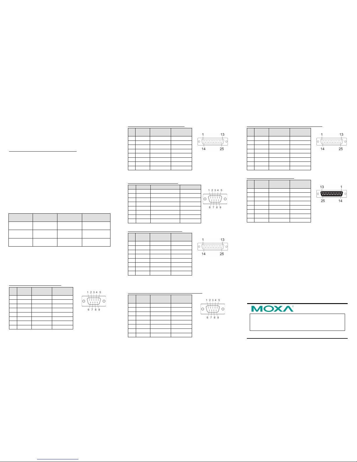
Pin Assignments
CP-118E-A-I / CP-138E-A-I
Male DB9 (CBL-M78M9x8-100)
Pin
RS-232
RS-422/
RS-485-4W
RS-485-2W
1
DCD
TxD-(A)
–
2
RxD
TxD+(B)
–
3
TxD
RxD+(B)
Data+(B)
4
DTR
RxD-(A)
Data-(A)
5
GND
GND
GND
6
DSR – – 7 RTS – –
8
CTS – –
DB9 male
Male DB25 (CBL-M78M25x8-100)
Pin
RS-232
RS-422/
RS-485-4W
RS-485-2W
2
TxD
RxD+(B)
Data+(B)
3
RxD
TxD+(B)
– 4 RTS – –
5
CTS – –
6
DSR – – 7 GND
GND
GND
8
DCD
TxD-(A)
–
20
DTR
RxD-(A)
Data-(A)
DB25 male
CP-134EL-A-I
Male DB9 (CBL-M44M9x4-50)
Pin
RS-232
RS-422/485-4W
RS-485-2W
1
DCD
TxD-(A)
–
2
RxD
TxD+(B)
–
3
TxD
RxD+(B)
Data+(B)
4
DTR
RxD-(A)
Data-(A)
5
GND
GND
GND
6
DSR – – 7 RTS – –
8
CTS – –
DB9 male
Male DB25 (CBL-M44M25x4-50)
Pin
RS-232
RS-422/
RS-485-4W
RS-485-2W
2
TxD
RxD+(B)
Data+(B)
3
RxD
TxD+(B)
–
4
RTS – – 5 CTS – –
6
DSR – –
7
GND
GND
GND 8 DCD
TxD-(A)
–
20
DTR
RxD-(A)
Data-(A)
DB25 male
CP-116E-A
Male DB9 (OPT8-M9+ / CBL-M68M9x8-100)
Pin
RS-232
RS-422/
RS-485-4W
RS-485-2W
1
DCD
TxD-(A)
– 2 RxD
TxD+(B)
–
3
TxD
RxD+(B)
Data+(B)
4
DTR
RxD-(A)
Data-(A)
5
GND
GND
GND
6
DSR – –
7
RTS – – 8 CTS – –
DB9 male
Male DB25 ( OPT8B+ / CBL-M68M25x8-100)
Pin
RS-232
RS-422/
RS-485-4W
RS-485-2W
2
TxD
RxD+(B)
Data+(B)
3
RxD
TxD+(B)
– 4 RTS – –
5
CTS – –
6
DSR – – 7 GND
GND
GND
8
DCD
TxD-(A)
–
20
DTR
RxD-(A)
Data-(A)
DB25 male
Female DB25 (OPT8A+/S+)
Pin
RS-232
RS-422/
RS-485-4W
RS-485-2W
2
RxD
TxD+(B)
–
3
TxD
RxD+(B)
Data+(B)
4
CTS – –
5
RTS – –
6
DTR
RxD-(A)
Data-(A)
7
GND
GND
GND
8
DCD
TxD-(A)
–
20
DSR – –
DB25 female
 Loading...