

Moxa Technologies CN2650-8, CN2610-8-2AC, CN2650-8-2AC-T, CN2650-8-2AC, CN2650-16 Quick Installation Manual
...
– 1 – – 2 – – 3 –
P/N: 1802026000214
CN2600 Series
Quick Installation Guide
Fourth Edition, Septemb er 2014
Overview
The Moxa CN2600 dual-LAN terminal servers have 8 or 16 RS-232
or RS-232/422/485 ports and dual 10/100 Mbps Ethernet LAN
ports, and some models come with dual AC power inputs. The
CN2600 terminal servers are used to connect terminals, modems,
printers, and other serial devices to LAN hosts, and all models
comply with TCP/IP and IEEE 802.3 specifications using standard
twisted pair 10 /100BaseTX cable as the transmissio n medium.
CN2600 Series Models
The CN2600 Series includes the following models: CN2610-8,
CN2610-8-2AC, CN2610-16, CN2610-16-2A C, CN2650-8,
CN2650-8-2AC-T, CN2650-8-2AC, CN2650-16, CN2650-16-2AC-T,
CN2650-16-2AC, CN2650I-8, CN2650I-8-2AC, CN2650I-16,
CN2650I-16-2AC, CN2650I-8-HV-T, CN2650I-16-HV-T.
Package Checklist
The CN2600 dual-LAN terminal server products are shipped with
the following it ems:
• 1 CN2600 series terminal server
• Power c ord (AC models only)*
• 1 DB9 serial cable (CBL-RJ45F9-150)
• 1 DB25 serial ca ble (CBL-RJ45M25-150)
• Rackmount kit (includes 2 brackets and 8 screws)
• Quick installation guide (this gu ide)
• Documentation and softwar e CD-ROM
* Power cords are available with US, Euro, UK, and JP plugs.
Hardware Introduction
NOTE
The wide temperature models do not come with the LCM
display panel and push buttons. The LCM description below
applies only to standard temperature models.
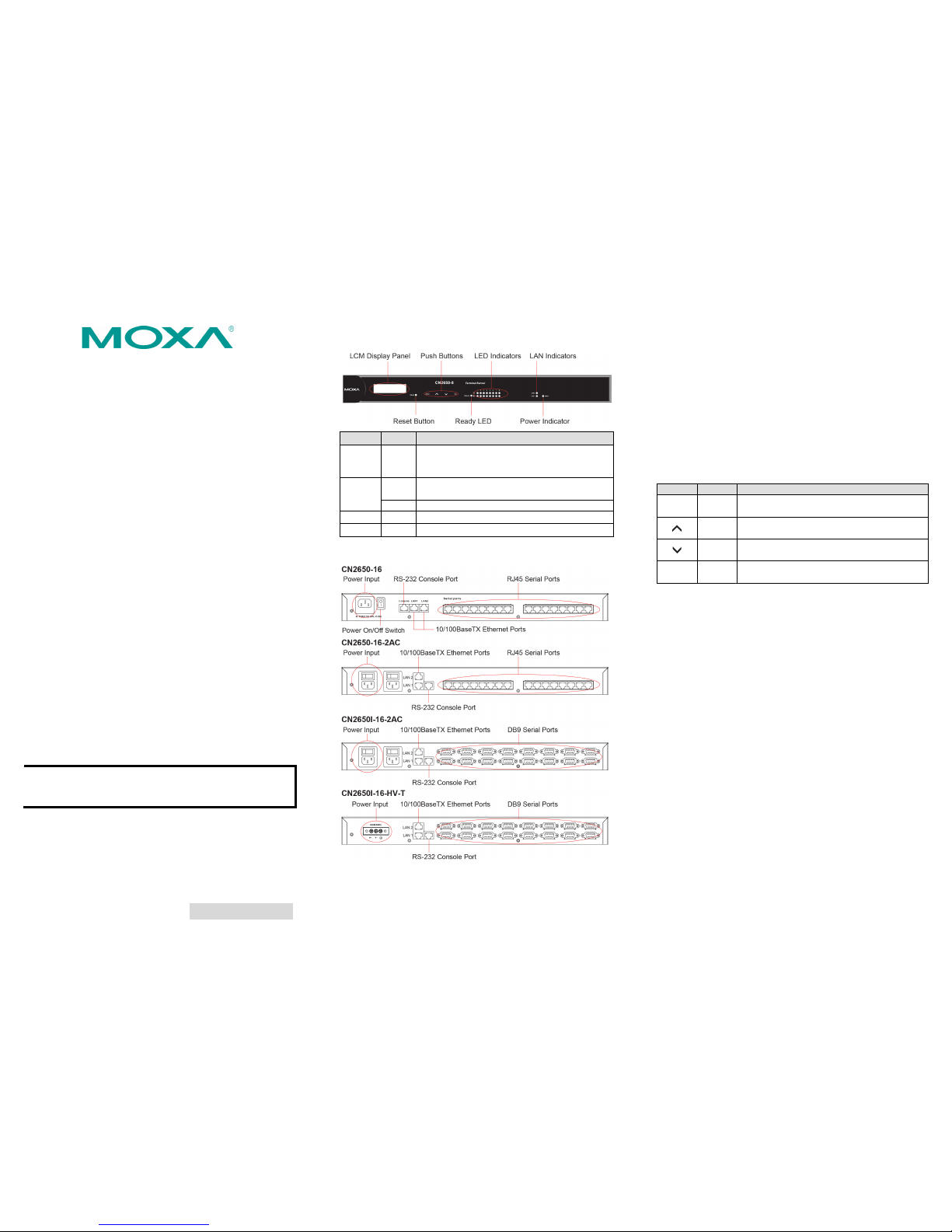
Front Panel
LED Color
Description
Reset None
Press the Reset button for 5 seconds to load
factory defaults. The CN2600 wi ll beep twice
when the configuration has been reset.
Ready
Red
Used for configuring the IP address and other
parameters.
Green
Lights up when the CN2600 system is ready.
Serial Tx
Green
Flashes to indicate serial port transmission.
Serial Rx Yellow
Flashes to indicate serial port reception.
Rear Panel
LCM Display
If the CN2600 is workin g properly, the LC M panel will displa y a
green color. The red Ready LED wil l also light up, in dicating that
the CN26 00 is receiving power. After the red Ready LED turns to
green, you will s ee a display simi lar to the followin g: (Example)
C N 2 6 1 0 - 1 6 _ 3
1 9 2 . 1 6 8 . 1 2 7 . 2 5 4
CN2610-16:
The CN26 10’s name
03:
The CN26 10’s local sequence number
192.168.127.254:
The CN26 10’s IP addr ess
There are four push buttons on the CN2600 nameplate:
Button
Name
Action
MENU menu
Activates the main menu, or returns to an
upper level.
up
cursor
Scrolls up through a list of items shown on the
LCM panel’s second line.
down
cursor
Scrolls down through a list of items shown on
the LCM panel’s second line.
SEL select
Selects the option listed on the LCM panel’s
second line.
Use the buttons to access the CN2600’s function menus. As you
move through the functions and settings, the top line shows the
current menu or submenu name, and the bottom line shows the
submenu name or menu item. Press the SEL button to access the
item displayed o n the bottom line .
Refer to CN2600 series User’s Manual for more details.
Hardware Installation
Installing the CN2600
Open the package and attach the CN2600 to a desktop, or fasten it
to the rack cabinet.
Wiring Requirements
1. Use separate paths to route wiring for power and devices. If
power wiring and device wiring paths must cross, make sure
the wires are perpendicular at the intersection point.
2. NOTE: Do not run signal or communication wiring and power
wiring in the same wire conduit. To avoid interference, wires
with different signal characteristics should be routed
separately.
3. Where necessar y, we strongly ad vise labeling wirin g to all
devices in the system.
– 4 – – 5 – – 6 –
www.moxa.com/support
The Americas:
+1-714-528-6777 (toll-free: 1-888-669-2872)
Europe:
+49-89-3 70 03 99-0
Asia-Pacific:
+886-2-8919-1230
China:
+86-21-5258-9955 (toll-free: 800-820-5036)
2014 Moxa Inc., All R ights Rese rved
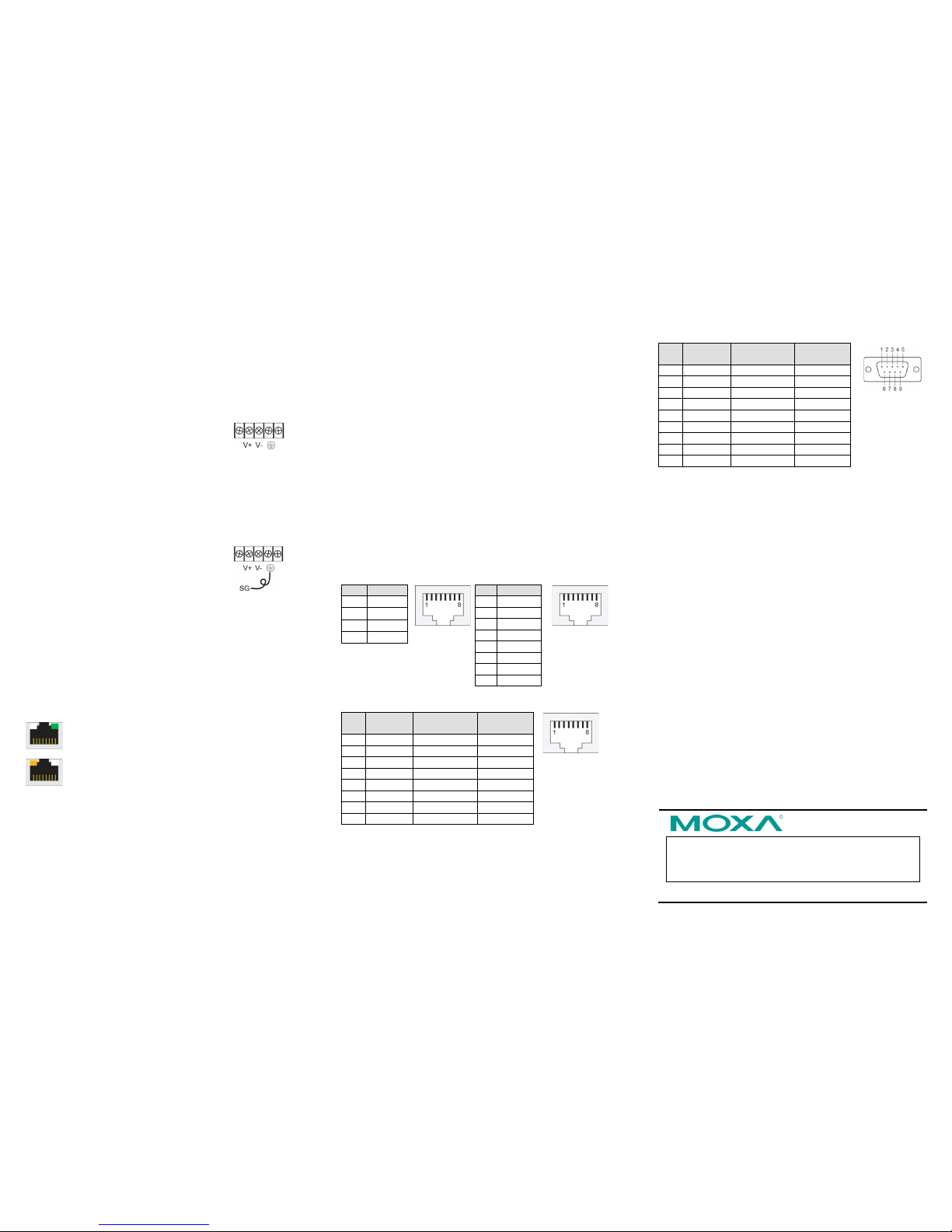
Connecting the Power
AC: Connect the CN2600 100-240 VAC p ower line with its AC
connector. If the power is properly supplied, the “Ready” LED will
show a solid red color until the system is ready, at which time the
“Ready” LED will change to a green color.
DC: Connect the NP ort CN2650I-HV’s power cord to the DC
connector, and then follow the steps given below:
Take
the CN2650I-8-HV-
T as an example. Loosen
the screws on th
e V+ and V- terminals of the
CN2650I-8-HV-T terminal block. Connec t the
power cord’s 100 VDC wire to the terminal block’s V+ terminal, and
the power cord’s DC
Power Ground wire to the terminal block’s V-
terminal, and then tighten the terminal block screws. (Note: The
CN2650I
-8-HV-T can still operate even if the DC Power Ground
wires
are reversed.) The “Ready” LED will show a solid red color
until the system is rea dy,
at which time it will change to a green
color.
Grounding the CN2650I-HV:
Grounding and wire routing help limit the effects
of noise due to electromagnetic interference
(EMI). Run the ground connection from the
ground screw to the grounding surface prior t
o
connecting devices. The Shielded Ground
(sometimes called Protected Ground) contact is the second contact
from the right of the 5-pin power terminal block connector located
on the rear panel of the CN2650I
-8-HV-
T. Connect the SG wire to
the Earth ground.
Connecting to the Network
Use an Ethernet cable to connect the CN2600 to the Ethe rnet
network. There are 2 LED indicators located on the top left and
right corners of the Ethernet connector. If the cable is properly
connected, the CN2600 will indicate a valid c onnection to the
Ethernet in the following ways:
The top right corner LED indicator maintains a solid
green color when the cable is properly connected to a
100 Mbps Ethernet network.
The top left corner LED indicator maintains a solid
orange color when the cable is properly connected to a
10 Mbps Ethernet network.
Connecting to a Serial Device
Connect the serial data cable between the CN2600 and the serial
device.
Connecting to a Console
A console is a combination of keyboard and monitor, and is used to
configure settings and to monitor the status of your system. If you
do not have a network environment, use a terminal, a PC running
UNIX, or a PC with terminal emulation software (e.g.,
HyperTerminal in Windows; PComm by Moxa). Use an
RJ45-to-DB25 or RJ45-to-DB9 cable to connect the terminal to the
console socket. Refer to the CN2600 User’s Manual for more
details.
Software Installation
Entering the Console Utility
The Console Ut ility is the main ap plication needed t o set up the
server/port configuration, and to execute utilities such as ping,
diagnosis, monitor, and upgrade. There are two ways to enter the
Console Utility. One is to use terminal emulation through a console
terminal, and the other is to telnet from a network terminal.
Refer to the CN2600 User’s Manual for more details.
Pin Assignments and Cable Wiring
10/100BaseTX Port Pinouts
Console Port Pinouts
Pin
Signal
1
Tx+ 2 Tx- 3 Rx+
6
Rx-
Pin
RS-232
1
DSR (in)
2
RTS (out)
3
GND
4
TxD (out)
5
RxD (in)
6
DCD (in)
7
CTS (in)
8
DTR (out)
RJ45 RS
-232/422/485 Port
Pin RS-232
RS-422/
RS-485-4w
RS-485-2w
1
DSR (in) – – 2 RTS (out)
TxD+
– 3 GND
GND
GND
4
TxD (out)
TxD-
– 5 RxD (in)
RxD+
Data+
6
DCD (in)
RxD-
Data-
7
CTS (in) – – 8 DTR (out) – –
DB9 (
male) RS-232/422/485 Port
Pin RS-232
RS-422/
RS-485-4w
RS-485-2w
1
DCD
TxD-(A)
– 2 RxD
TxD+(B)
– 3 TxD
RxD+(B)
Data+(B)
4
DTR
RxD-(A)
Data-(A)
5
GND
GND
GND 6 DSR – – 7 RTS – – 8 CTS – – 9 – – –
 Loading...