

Moxa Technologies CN2610-16-2AC, CN2610-16, CN2650-8, CN2650-8-2AC-T, CN2650-16 Quick Installation Manual
...Page 1

P/N: 1802026000217
*1802026000217*
CN2600 Series
Quick Installation Guide
Edition 6.1, November 2018
Technical Support Contact Information
www.moxa.com/support
Moxa Americas:
Toll
-free: 1-888-669-2872
Tel:
1-714-528-6777
Fax:
1-714-528-6778
Moxa China (Shanghai office):
Toll
-free: 800-820-5036
Tel:
+86-21-5258-9955
Fax:
+86-21-5258-5505
Moxa Europe:
Tel:
+49-89-3 70 03 99-0
Fax:
+49-89-3 70 03 99-99
Moxa Asia-Pacific:
Tel:
+886-2-8919-1230
Fax:
+886-2-8919-1231
Moxa India:
Tel:
+91-80-4172-9088
Fax:
+91-80-4132-1045
2018 Moxa Inc. All rights reserved.
Page 2
- 2 -
Overview
The Moxa CN2600 dual-LAN terminal servers have 8 or 16 RS-232 or
RS-232/422/485 ports and dual 10/100 Mbps Ethernet LAN ports, and
some models come with dual AC power inputs. The CN2600 terminal
servers are used to connect terminals, modems, printers, and other
serial devices to LAN hosts, and all models comply with TCP/IP and
IEEE 802.3 specifications using standard twisted pair 10/100BaseTX
cable as the transmission medium.
CN2600 Series Models
The CN2600 Series includes the following models: CN2610-8, CN26108-2AC, CN2610-16, CN2610-16-2AC, CN2650-8, CN2650-8-2AC-T,
CN2650-8-2AC, CN2650-16, CN2650-16-2AC-T, CN2650-16-2AC,
CN2650I-8, CN2650I-8-2AC, CN2650I-16, CN2650I-16-2AC, CN2650I8-HV-T, CN2650I-16-HV-T.
Package Checklist
The CN2600 dual-LAN terminal server products are shipped with the
following items:
• 1 CN2600 Series terminal server
• Power cord (AC models only)*
• 1 DB9 serial cable (CBL-RJ45F9-150)
• 1 DB25 serial cable (CBL-RJ45M25-150)
• Rackmount kit (includes 2 brackets and 8 screws)
• Quick installation guide (this guide)
*Power cords are available with US, Euro, UK, and JP plugs.
Hardware Introduction
NOTE
The wide temperature models do not come with the LCM
display panel and push buttons. The LCM description below
applies only to standard temperature models.
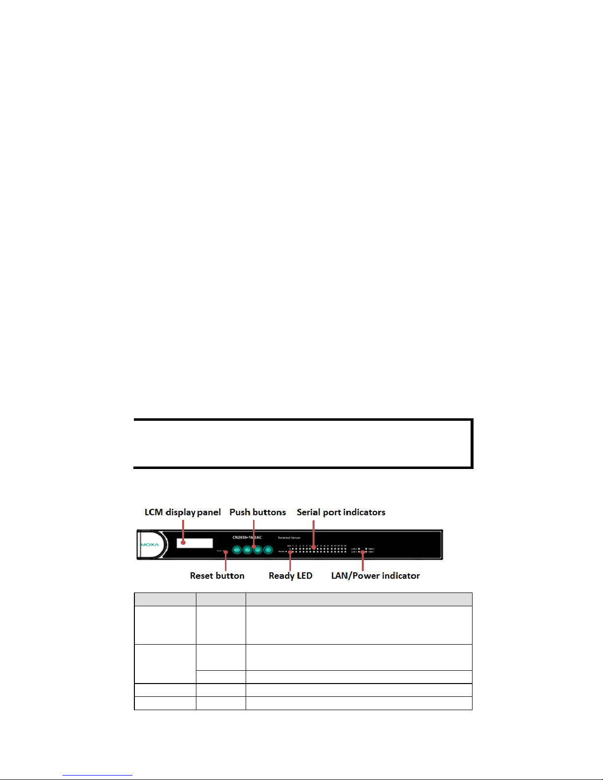
Front Panel
LED
Color
Description
Reset None Press the Reset button for 5 seconds to load
factory defaults. The CN2600 will beep twice
when the configuration has been reset.
Ready
Red
Used for configuring the IP address and other
parameters.
Green
Lights up when the CN2600 system is ready.
Serial Tx
Green
Flashes to indicate serial port transmission.
Serial Rx
Yellow
Flashes to indicate serial port reception.
Page 3

- 3 -
Rear Panel
CN2650-16
CN2650-16-2AC
CN26501-16-2AC
CN26501-16-HV-T
LCM Display
If the CN2600 is working properly, the LCM panel will display a green
color. The red Ready LED will also light up, indicating that the CN2600
is receiving power. After the red Ready LED turns to green, you will see
a display similar to the following: (Example)
C N 2 6 1 0 - 1 6 _ 3 1 9 2 . 1 6 8 . 1 2 7 . 2 5 4
CN2610-16:
The CN2610’s name
03:
The CN2610’s local sequence number
192.168.127.254:
The CN2610’s IP address
There are four push buttons on the CN2600 nameplate:
Button
Name
Action
MENU
menu
Activates the main menu, or returns to an
upper level.
up cursor Scrolls up through a list of items shown on the
LCM panel’s second line.
down cursor
Scrolls down through a list of items shown on
the LCM panel’s second line.
SEL
select
Selects the option listed on the LCM panel’s
second line.
Page 4

- 4 -
Use the buttons to access the CN2600’s function menus. As you move
through the functions and settings, the top line shows the current menu
or submenu name, and the bottom line shows the submenu name or
menu item. Press the SEL button to access the item displayed on the
bottom line.
Refer to the CN2600 Series User’s Manual for more details.
Hardware Installation
Installing the CN2600
Open the package and attach the CN2600 to a desktop, or fasten it to
the rack cabinet.
Wiring Requirements
1. Use separate paths to route wiring for power and devices. If power
wiring and device wiring paths must cross, make sure the wires are
perpendicular at the intersection point.
NOTE: Do not run signal or communication wiring and power wiring
in the same wire conduit. To avoid interference, wires with different
signal characteristics should be routed separately.
2. Where necessary, we strongly advise labeling wiring to all devices
in the system.
Connecting the Power
AC: Connect the CN2600 100-240 VAC power line with its AC
connector. If the power is properly supplied, the “Ready” LED will show
a solid red color until the system is ready, at which time the “Ready”
LED will change to a green color.
DC: Connect the NPort CN2650I-HV’s power cord to the DC connector,
and then follow the steps given below:
Take the CN2650I-8-HV-T as an example. Loosen the
screws on the V+ and V
- terminals of the CN2650I-8-
HV-T terminal block. Connect the power
cord’s 100 VDC wire to the terminal block’s V+ terminal, and the power
cord’s DC Power Ground wire to the terminal block’s V
- terminal, and
then tighten the terminal block screws. (Note: The CN2650I
-8-HV-T
can still operate even if the DC Power Ground wires are
reversed.) The
“Ready” LED will show a solid red color until the system is ready, at
which time it will change to a green color.
Grounding the CN2650I-HV:
Grounding and wire routing help limit the effects of
noise due to electromagnetic interference (EMI). Run
the ground connection from the ground screw to the
grounding surface prior to connecting devices. The
Shielded Ground
(sometimes called Protected
Ground)
contact is the second contact from the right of the 5-pin power terminal
block connector located on the rear panel of the CN2650I
-8-HV-T.
Connect the SG wire to the Earth ground.
Page 5

- 5 -
Connecting to the Network
Use an Ethernet cable to connect the CN2600 to the Ethernet network.
There are 2 LED indicators located on the top left and right corners of
the Ethernet connector. If the cable is properly connected, the CN2600
will indicate a valid connection to the Ethernet in the following ways:
The top right corner LED indicator maintains a solid green
color when the cable is properly connected to a 100 Mbps
Ethernet network.
The top left corner LED indicator maintains a solid orange
color when the cable is properly connected to a 10 Mbps
Ethernet network.
Connecting to a Serial Device
Connect the serial data cable between the CN2600 and the serial
device.
Connecting to a Console
A console is a combination of keyboard and monitor, and is used to
configure settings and to monitor the status of your system. If you do
not have a network environment, use a terminal, a PC running UNIX, or
a PC with terminal emulation software (e.g., HyperTerminal in
Windows; PComm by Moxa). Use an RJ45-to-DB25 or RJ45-to-DB9
cable to connect the terminal to the console socket. Refer to the
CN2600 User’s Manual for more details.
Software Installation
For the NPort’s configuration, the default IP address of the NPort
is:LAN: Static; IP = 192.168.127.254; netmask = 255.255.255.0
NOTE
If you have forgotten the NPort's IP address, use the Device
Search Utility (DSU) from your PC to locate the NPort. After
searching the LAN for NPort units, the DSU will display the IP
address of each unit.
You may log in with the password moxa to change any setting to meet
your network topology (e.g., IP address) or serial device (e.g., serial
parameters). For first-time use, click the Wizard in the left navigation
panel. The wizard will prompt you to configure the IP address, SSID,
and security mode. For other settings, use the factory defaults or
modify the settings for your application.
For software installation, download the relative utilities from Moxa's
website:
https://www.moxa.com/support/support_home.aspx?isSearchShow=1
• Download the NPort Windows Driver Manager and install it as the
driver to run with Real COM mode of the NPort Series.
• Execute NPort Windows Driver Manager; then map the virtual COM
ports on your Windows platform.
Page 6

- 6 -
• For Loopback Wiring:
。The NPort with RJ45 Port :
You may refer to the RJ45 Ports pin assignment section to loop
back pin 4 and pin 5 for the RS-232 interface to carry out a self test
on the device.
• 。 The NPort with DB9 Male Serial Ports:
You may refer to the DB9 Male Ports pin assignment section to loop
back pin 2 and pin 3 for the RS-232 interface to carry out a self test
on the device.
• Use HyperTerminal or a similar program (you may download Moxa's
program, called PComm Lite) to test whether the device is good or
not.
Please refer to the CN600 Async Server User’s Manual for more details.
Pin Assignments and Cable Wiring
10/100BaseTX Port Pinouts
Console Port Pinouts
Pin
Signal
1
Tx+
2
Tx-
3
Rx+
6
Rx-
Pin
RS-232
1
DSR (in)
2
RTS (out)
3
GND
4
TxD (out)
5
RxD (in)
6
DCD (in)
7
CTS (in)
8
DTR (out)
RJ45 RS
-232/422/485 Port
Pin RS-232
RS-422/
RS-485-4w
RS-485-2w
1
DSR (in)
–
–
2
RTS (out)
TxD+
–
3
GND
GND
GND
4
TxD (out)
TxD-
–
5
RxD (in)
RxD+
Data+
6
DCD (in)
RxD-
Data-
7
CTS (in)
–
–
8
DTR (out)
–
–
DB9 (
male) RS-232/422/485 Port
Pin RS-232
RS-422/
RS-485-4w
RS-485-2w
1
DCD
TxD-(A)
–
2
RxD
TxD+(B)
–
3
TxD
RxD+(B)
Data+(B)
4
DTR
RxD-(A)
Data-(A)
5
GND
GND
GND
6
DSR – –
7
RTS – –
8
CTS – – 9 – – –
 Loading...