

Moxa Technologies CN2610 Quick Installation Manual
— 1 — — 2 — — 3 —
CN2610 Series
Quick Installation Guide
Fourth Edition, August 2007
1. Overview
Welcome to the Moxa CN2610 dual-LAN terminal server, a
communication server with 8 or 16 RS-232 ports and dual 10/100 Mbps
Ethernet LAN ports. The CN2610 dual-LAN terminal server can be used
to connect terminals, modems, printers, and other serial devices to LAN
hosts. Rhw CN2610 complies with TCP/IP and IEEE 802.3 specifications
using standard Ethernet 10/100BaseT and twisted pair 10/100BaseTX
cable as the transmission medium.
2. Package Checklist
The CN2610 dual-LAN terminal server products are shipped with the
following items:
y 1 CN2610 Terminal Server
y 1 power cord (AC models only)*
y Document and & Software CD-ROM
y Quick Installation Guide (this guide)
y 1 DB9 serial cable (CBL-RJ45F9-150)
y 1 DB25 serial cable (CBL-RJ45M25-150)
* Power cords are available with US, Euro, UK, and JP plugs.
Optional Accessories
y CBL-RJ45M9-150: RJ45 (8-pin) to DB9 (male) cable, 150 cm
y CBL-RJ45F9-150: RJ45 (8-pin) to DB25 (female) cable, 150 cm
y CBL-RJ45M25-150: RJ45 (8-pin) to DB25 (male) cable, 150 cm
y CBL-RJ45F25-150: RJ45 (8-pin) to DB25 (female) cable, 150 cm
NOTE: Notify your sales representative if any of the above items are
missing or damaged.
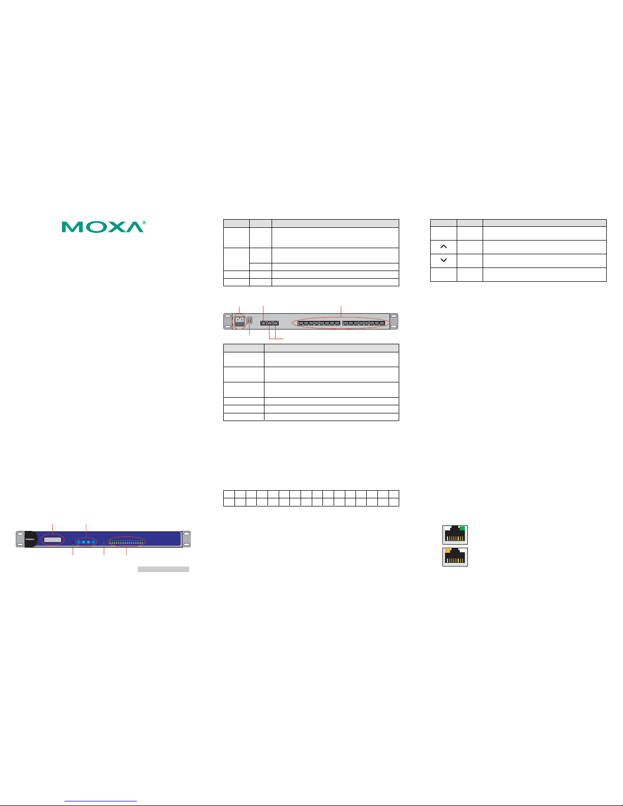
3. Hardware Introduction
Front Panel
Rx
Tx
12345678910111213141516
Reset
Ready
SELMENU
CN2610
16 port RS-232 Async Server
LCM Display Panel
Reset Button Ready LED
Push Buttons
LED Indicators
LED Color Description
Reset None
Press the Reset button for 5 seconds to load factory
defaults. The CN2610 will beep twice when the
configuration has been reset.
Red
Used for configuring the IP address and other
parameters.
Ready
Green Lights up when the CN2610 system is ready.
Serial Tx Green Flashes to indicate serial port transmission.
Serial Rx Yellow Flashes to indicate serial port reception.
Rear Panel
12345678
Serial ports
AC POWER 100-240V, 47-63Hz
Console LAN1 LAN2
910111213141516
10/100BaseT Ethernet Ports
RS-232 Console Port
Serial PortsPower Input
Power On/Off Switch
Connector Function
AC Power
Input
Automatic detection of 100-240V, 47-63 Hz AC power
supply (CN2610-8 or CN2610-16).
Power On/Off
Switch
I indicates power on; O indicates power off.
RS-232
Console Port
One RJ45 connector for console terminal connection.
LAN1 Auto detecting 10/100 Mbps port.
LAN2 Auto detecting 10/100 Mbps port.
Serial Ports 8 or 16 RJ45 connectors for DCE (modem) connections.
LCM Display
We recommend using the LCM display and four push buttons to
configure the IP address for the first time.
Basic Operation
If the CN2610 is working properly, the LCM panel will display a green
color. The red Ready LED will also light up, indicating that the CN2610
is receiving power. After the red Ready LED turns to green, you will see a
display similar to the following:
C N 2 6 1 0 - 1 6 _ 3
1 9 2 . 1 6 8 . 1 2 7 . 2 5 4
CN2610-16: The CN2610’s name
03: The CN2610’s serial number
192.168.127.254: The CN2610’s IP address
There are four push buttons on the CN2610’s nameplate. Going from left
to right, the buttons are:
Button Name Action
MENU menu
Activates the main menu, or returns to an upper
level.
up cursor
Scrolls up through a list of items shown on the
LCM panel’s second line.
down
cursor
Scrolls down through a list of items shown on the
LCM panel’s second line.
SEL select
Selects the option listed on the LCM panel’s
second line.
The buttons are manipulated in a manner similar to the way a modern
cellular phone operates. As you move through the various functions and
setting options, note that the top line shows the current menu or submenu
name, and the bottom line shows the submenu name or menu item that is
activated by pressing the SEL button.
Refer to CN2610 User’s Manual for more details.
4. Hardware Installation
1. Installing the CN2610
Open the package, and attach the CN2610 to a desktop, or fasten it to
the rack cabinet.
2. Wiring Requirements
A. Use separate paths to route wiring for power and devices. If power
wiring and device wiring paths must cross, make sure the wires are
perpendicular at the intersection point.
B. NOTE: Do not run signal or communication wiring and power
wiring in the same wire conduit. To avoid interference, wires with
different signal characteristics should be routed separately.
C. Where necessary, we strongly advised that you label wiring to all
devices in the system.
3. Connecting Power
AC: Connect the CN2610 100-240 VAC power line with its AC
connector. If the power is properly supplied, the “Ready” LED
will show a solid red color until the system is ready, at which
time the “Ready” LED will change to a green color.
If the power is properly supplied, the “Ready” LED will show a solid
red color until the system is ready, at which time the “Ready” LED
will change to a green color.
4. Connecting to the Network
Connect one end of the Ethernet cable to the CN2610’s 10/100M
Ethernet port and the other end of the cable to the Ethernet network.
There are 2 LED indicators located on the top left and right corners of
the Ethernet connector. If the cable is properly connected, the CN2610
will indicate a valid connection to the Ethernet in the following ways:
The top right corner LED indicator maintains a solid
green color when the cable is properly connected to a
100 Mbps Ethernet network.
The top left corner LED indicator maintains a solid
orange color when the cable is properly connected to a
10 Mbps Ethernet network.
5. Connecting to a Serial Device
P/N: 1802026000213
— 4 — — 5 — — 6 —
Connect the serial data cable between the CN2610 and the serial
device.
6. Connecting to a Console
A console is a combination of keyboard and monitor, and is used to
configure settings and to monitor the status of your system. If you do
not have a network environment, use a terminal, a PC running UNIX,
or a PC with terminal emulation software (e.g., HyperTerminal in
Windows; PComm by Moxa). Use an RJ45-to-DB25 or RJ45-to-DB9
cable to connect the terminal to the console socket. Refer to the
CN2610 User’s Manual for more details.
5. Software Installation
Entering the Console Utility
Console Utility is the main application needed to set up the server/port
configuration, and to execute utilities such as ping, diagnosis, monitor,
and upgrade. There are two ways to enter the Console Utility. One is to
use terminal emulation through a console terminal, and the other is to
telnet from a network terminal.
Refer to the CN2610 User’s Manual for more details.
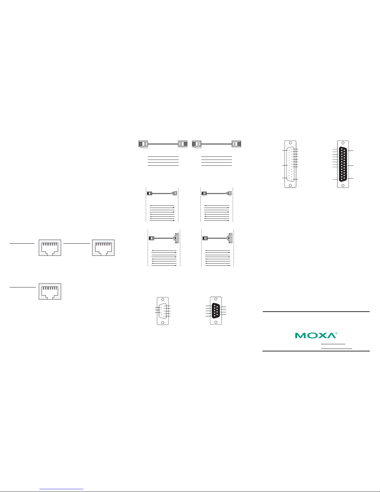
6. Pin Assignments and Cable Wiring
10/100BaseTX Port Pinouts Console Port Pinouts
Pin Signal
1 Tx+
2 Tx3 Rx+
6 Rx-
18
Pin RS-232
1 DSR (in)
2 RTS (out)
3 GND
4 TxD (out)
5 RxD (in)
6 DCD (in)
7 CTS (in)
8 DTR (out)
18
RS-232 Port Pinouts
Pin RS-232
1 DSR (in)
2 RTS (out)
3 GND
4 TxD (out)
5 RxD (in)
6 DCD (in)
7 CTS (in)
8 DTR (out)
18
10/100BaseTX Cable Wiring
Straight-Through Cable
RJ45 Plug Pin 1
Cable Wiring
3 3
6 6
1 1
2 2
Cross-Over Cable
RJ45 Plug Pin 1
Cable Wiring
3 1
6 2
1 3
2 6
RS-232 Cable Wiring
NOTE: The following cables are optional accessories.
CBL-RJ45M9-150 CBL-RJ45F9-150
DSR
RTS
GND
TxD
RxD
DCD
CTS
DTR
RS-232
Device
DTR
CTS
GND
RxD
TxD
DCD
RTS
DSR
Cable Wiring
1
2
3
4
5
6
7
8
6
7
5
3
2
1
8
4
Male DB9 Female DB9
RJ45 ConnectorRJ45 Port
9 pins8 pins
DSR
RTS
GND
TxD
RxD
DCD
CTS
DTR
RS-232
Device
DTR
CTS
GND
RxD
TxD
DCD
RTS
DSR
Cable Wiring
1
2
3
4
5
6
7
8
4
8
5
2
3
1
7
6
Male DB9Female DB9
RJ45 ConnectorRJ45 Port
9 pins8 pins
CBL-RJ45M25-150 CBL-RJ45F25-150
DSR
RTS
GND
TxD
RxD
DCD
CTS
DTR
RS-232
Device
DTR
CTS
GND
RxD
TxD
DCD
RTS
DSR
Cable Wiring
1
2
3
4
5
6
7
8
6
4
7
2
3
8
5
20
Male DB25 Female
DB25
RJ45 ConnectorRJ45 Port
25 pins8 pins
DSR
RTS
GND
TxD
RxD
DCD
CTS
DTR
RS-232
Device
DTR
CTS
GND
RxD
TxD
DCD
RTS
DSR
Cable Wiring
1
2
3
4
5
6
7
8
20
5
7
3
2
8
4
6
Male
DB25
Female DB25RJ45 ConnectorRJ45 Port
25 pins8 pins
DB9 and DB25 Connector Pinouts
The following figures illustrate standard connector pinouts. However,
pinouts for serial devices differ from manufacturer to manufacturer. Refer
to the serial device’s user’s manual for the exact pinouts of your device.
Male DB9 Connector Female DB9 Connector
1 DCD (in)
2 RxD (in)
3 TxD (out)
4 DTR (out)
5 GND
RTS (out) 7
CTS (in) 8
DSR (in) 6
DCD (in) 1
RxD (in) 2
TxD (in) 3
DSR (in) 4
GND 5
7 CTS (in)
8 RTS (out)
9 ---
6 DTR (out)
Male DB25 Connector Female DB25 Connector
1
2 TxD (out)
3 RxD (in)
4 RTS (out)
5 CTS (in)
6 DSR (in)
7 GND
8 DCD (in)
13
DTR (out) 20
25
14
1
RxD (in) 2
TxD (out) 3
CTS (in) 4
RTS (out) 5
DTR (out) 6
GND 7
DCD (in) 8
13
20 DSR (in)
25
14
7. Environmental Specifications
Power requirements
Power Input 100 to 240 VAC, 47 to 63 Hz
Power Consumption
CN2610-8/16
235 mA for 100V, 145 mA for 240V
Operating temperature 0 to 55◦C (32 to 131◦F)
Storage temperature -20 to 70◦C (-4 to 158◦F), 5 to 95% RH
198 × 45 × 440 mm Dimensions (W×D×H)
(7.8 × 1.77 × 17.3 in)
Surge protection 15 KV ESD for serial ports
Magnetic isolation 1.5 KV for Ethernet ports
Power line protection
1 KV Burst (EFT), EN61000-4-4
2 KV Surge, EN61000-4-5
Regulatory approvals EMC: CE: EN55022 Class A/EN55024
FCC: FCC part 15 subpart B, Class A
Safety: UL: UL60950
TUV: EN60950
Copyright © 2007
Moxa Technologies Co., Ltd.
All rights reserved.
Reproduction without permission is prohibited.
Tel: +886-2-8919-1230 www.moxa.com
Fax: +886-2-8919-1231 support@moxa.com
 Loading...