

Page 1

CN2510 Async Server User’s Manual
Edition 7.0, January 2018
www.moxa.com/product
© 2018 Moxa Inc. All rights reserved.
Page 2

CN2510 Async Server User’s Manual
Moxa Americas
Toll
Tel:
Fax:
Moxa China (Shanghai office)
Toll
Tel:
Fax:
Moxa Europe
Tel:
Fax: +49-89-3 70 03 99-99
Moxa Asia
Tel:
Fax: +886-2-8919-1231
Moxa India
Tel:
Fax:
The software described in this manual is furnished under a license agreement and may be used only in accordance with
the terms of that agreement.
Copyright Notice
© 2018 Moxa Inc. All rights reserved.
Trademarks
The MOXA logo is a registered trademark of Moxa Inc.
All other trademarks or registered marks in this manual belong to their respective manufacturers.
Disclaimer
Information in this document is subject to change without notice and does not represent a commitment on the part of
Moxa.
Moxa provides this document as is, without warranty of any kind, either expressed or implied, including, but not limited
to, its particular purpose. Moxa reserves the right to make improvements and/or changes to this manual, or to the
products and/or the programs described in this manual, at any time.
Information provided in this manual is intended to be accurate and reliable. However, Moxa assumes no responsibility for
its use, or for any infringements on the rights of third parties that may result from its use.
This product might include unintentional technical or typographical errors. Changes are periodically made to the
information herein to correct such errors, and these changes are incorporated into new editions of the publication.
Technical Support Contact Information
www.moxa.com/support
-free: 1-888-669-2872
+1-714-528-6777
+1-714-528-6778
+49-89-3 70 03 99-0
-free: 800-820-5036
+86-21-5258-9955
+86-21-5258-5505
+886-2-8919-1230
-Pacific
+91-80-4172-9088
+91-80-4132-1045
Page 3

Table of Contents
1. Introduction ...................................................................................................................................... 1-1
Product Features ................................................................................................................................ 1-2
Hardware ................................................................................................................................... 1-2
Software .................................................................................................................................... 1-2
Package Checklist ............................................................................................................................... 1-2
Front Panel ........................................................................................................................................ 1-3
Rear Panel ......................................................................................................................................... 1-3
2. Getting Started.................................................................................................................................. 2-1
Hardware Installation .......................................................................................................................... 2-2
Desktop ..................................................................................................................................... 2-2
Rackmount ................................................................................................................................. 2-2
Wiring Requirements ................................................................................................................... 2-2
Connecting CN2510-8/16’s Power.................................................................................................. 2-3
Connecting CN2510-8/16-48V’s Power ........................................................................................... 2-3
Grounding CN2510-8/16-48V ........................................................................................................ 2-3
Connecting to the Network ........................................................................................................... 2-4
Connecting to a Serial Device ....................................................................................................... 2-4
Connecting to the Console Port ..................................................................................................... 2-4
Accessing the Console Utility ................................................................................................................ 2-4
Configuration Checklist ................................................................................................................ 2-4
Accessing the Console from a Telnet Terminal ................................................................................. 2-5
Accessing the Console from a Console Terminal .............................................................................. 2-7
Configuring CN2510—The Server Menu ............................................................................................... 2-12
Server Configuration—Info. ........................................................................................................ 2-12
Server Configuration—LAN ......................................................................................................... 2-13
Server Configuration—Adv. ......................................................................................................... 2-14
Server Configuration—Host_table ................................................................................................ 2-16
Server Configuration—Route_table .............................................................................................. 2-16
Server Configuration—User_table ................................................................................................ 2-17
Save ............................................................................................................................................... 2-18
Restart ............................................................................................................................................ 2-18
3. Knowing Your Application ................................................................................................................. 3-1
Windows Real COM (NT Real COM) ....................................................................................................... 3-2
Linux Real TTY/Unix Fixed TTY (NT Real COM) ........................................................................................ 3-3
Device Control (Device Control) ............................................................................................................ 3-4
UDP Communication (Raw UDP) ........................................................................................................... 3-5
Console Management (Reverse Terminal) .............................................................................................. 3-6
Terminal Access (Terminal) .................................................................................................................. 3-7
Multi-host TTY (Multi-host TTY) ............................................................................................................ 3-8
Dial-in/Out-of-Band Management (Dialin/out) ........................................................................................ 3-9
Network Printer (Printer) ................................................................................................................... 3-10
Multiplexor Access (Multiplex) ............................................................................................................ 3-11
4. Setting Up Windows Real COM/Linux Real TTY/Unix Fixed TTY ........................................................ 4-1
Accessing the Console Utility ................................................................................................................ 4-2
Selecting the Application ..................................................................................................................... 4-2
Configuring ASPP Mode ....................................................................................................................... 4-4
Configuring the Serial Ports.................................................................................................................. 4-5
Save ................................................................................................................................................. 4-6
Restart .............................................................................................................................................. 4-6
Setting up Hosts ................................................................................................................................. 4-7
Setting up Windows XP/2003 Hosts ............................................................................................... 4-7
Setting up Windows 2000 Hosts .................................................................................................. 4-22
Setting up Windows 95/98/ME/NT Hosts ...................................................................................... 4-35
5. Setting Up Device Control ................................................................................................................. 5-1
Accessing the Console Utility ................................................................................................................ 5-2
Selecting the Application ..................................................................................................................... 5-2
Configuring ASPP Mode ....................................................................................................................... 5-4
Configuring RAW Mode ........................................................................................................................ 5-6
Configuring the Serial Ports.................................................................................................................. 5-7
Save ................................................................................................................................................. 5-8
Restart .............................................................................................................................................. 5-8
ASPP Library Introduction .................................................................................................................... 5-9
ASPP Examples for Unix....................................................................................................................... 5-9
ASPP Examples for Windows .............................................................................................................. 5-10
6. Setting Up Raw UDP .......................................................................................................................... 6-1
Accessing the Console Utility ................................................................................................................ 6-2
Page 4

Selecting the Application ..................................................................................................................... 6-2
Configuring RAW UDP Mode ................................................................................................................. 6-4
Configuring the Serial Ports.................................................................................................................. 6-5
Save ................................................................................................................................................. 6-6
Restart .............................................................................................................................................. 6-7
7. Setting Up Reverse Terminal ............................................................................................................. 7-1
Accessing the Console Utility ................................................................................................................ 7-2
Selecting the Application ..................................................................................................................... 7-2
Configuring RTELNET Mode .................................................................................................................. 7-4
Configuring the Serial Ports.................................................................................................................. 7-5
Save ................................................................................................................................................. 7-6
Restart .............................................................................................................................................. 7-6
8. Setting Up Terminal .......................................................................................................................... 8-1
Accessing the Console Utility ................................................................................................................ 8-2
Selecting the Application ..................................................................................................................... 8-2
Configuring TERM_ASC Mode ............................................................................................................... 8-4
Configuring TERM_BIN Mode ................................................................................................................ 8-6
Configuring the Serial Ports.................................................................................................................. 8-8
Save ................................................................................................................................................. 8-9
Restart ............................................................................................................................................ 8-10
9. Setting Up Multi-host TTY ................................................................................................................. 9-1
Accessing the Console Utility ................................................................................................................ 9-2
Selecting the Application ..................................................................................................................... 9-2
Configuring FIXTTY Mode ..................................................................................................................... 9-4
Configuring the Serial Ports.................................................................................................................. 9-5
Save ................................................................................................................................................. 9-6
Restart .............................................................................................................................................. 9-6
Setting up Hosts ................................................................................................................................. 9-7
Installing and Compiling Moxatty ................................................................................................... 9-7
Moxatty for Different Applications .................................................................................................. 9-8
Using Moxatty ............................................................................................................................. 9-9
10. Setting Up Dialin/out ...................................................................................................................... 10-1
Accessing the Console Utility .............................................................................................................. 10-2
Selecting the Application ................................................................................................................... 10-2
Configuring PPPD/PPP Mode ............................................................................................................... 10-4
Configuring SLIPD/SLIP Mode ............................................................................................................. 10-6
Configuring Dynamic Mode ................................................................................................................ 10-8
Configuring the Serial Ports.............................................................................................................. 10-12
Configuring Modem Initialization ....................................................................................................... 10-13
Optional Welcome Message .............................................................................................................. 10-14
Configuring Optional Local User Information ....................................................................................... 10-14
Save ............................................................................................................................................. 10-15
Restart .......................................................................................................................................... 10-16
11. Setting Up Printer ........................................................................................................................... 11-1
Accessing the Console Utility .............................................................................................................. 11-2
Selecting the Application ................................................................................................................... 11-2
Configuring RAW PRN Mode ............................................................................................................... 11-4
Configuring LPD PRN Mode ................................................................................................................. 11-5
Configuring the Serial Ports................................................................................................................ 11-6
Save ............................................................................................................................................... 11-7
Restart ............................................................................................................................................ 11-8
Setting up Unix Hosts ........................................................................................................................ 11-8
Setting up a SCO Unix Host ........................................................................................................ 11-9
Setting up a SOLARIS X86 Host ................................................................................................ 11-10
Setting up a LINUX Host ........................................................................................................... 11-11
Setting up Windows Hosts ............................................................................................................... 11-12
Setting up a Windows NT Host .................................................................................................. 11-12
Setting up a Windows 2000 Host ............................................................................................... 11-15
12. Setting Up Multiplex ........................................................................................................................ 12-1
Accessing the Console Utility .............................................................................................................. 12-2
Selecting the Application ................................................................................................................... 12-3
Configuring the “Host” CN2510 ........................................................................................................... 12-3
Configuring the “Device” CN2510 ........................................................................................................ 12-6
Configuring the Serial Ports.............................................................................................................. 12-10
Save ............................................................................................................................................. 12-11
Restart .......................................................................................................................................... 12-12
13. Setting Up Routing .......................................................................................................................... 13-1
Accessing the Console Utility .............................................................................................................. 13-2
What is RIP? .................................................................................................................................... 13-2
Page 5

Configuring RIP ................................................................................................................................ 13-3
Configuring the Static Routing Table ................................................................................................... 13-4
Static Routing Examples .................................................................................................................... 13-5
Configuring Routes to the Internet .............................................................................................. 13-5
Configuring Routes to the Internet and Intranet ............................................................................ 13-6
Configuring Multiple-Point Routes ................................................................................................ 13-7
Save ............................................................................................................................................... 13-8
Restart ............................................................................................................................................ 13-8
14. Administrative Utilities.................................................................................................................... 14-1
Ping ................................................................................................................................................ 14-2
Monitor............................................................................................................................................ 14-2
Line ......................................................................................................................................... 14-3
Network ................................................................................................................................... 14-4
Async ...................................................................................................................................... 14-5
Routing .................................................................................................................................... 14-6
PPP-Trace ................................................................................................................................. 14-7
Diagnostic........................................................................................................................................ 14-7
Upgrade .......................................................................................................................................... 14-8
Upgrading with the Windows Utility ............................................................................................. 14-8
Console Terminal Upgrade ........................................................................................................ 14-10
Upgrading through the Serial Console ........................................................................................ 14-11
Remote RCP Upgrade ............................................................................................................... 14-14
Export ........................................................................................................................................... 14-16
Console Terminal Export .......................................................................................................... 14-16
Remote RCP Export ................................................................................................................. 14-18
Import .......................................................................................................................................... 14-19
Console Terminal Import .......................................................................................................... 14-19
Remote RCP Import ................................................................................................................. 14-21
Default .......................................................................................................................................... 14-22
15. Android API Instructions ................................................................................................................ 15-1
Overview ......................................................................................................................................... 15-2
How to Start MxNPortAPI ........................................................................................................... 15-2
MxNPortAPI Function Groups .............................................................................................................. 15-3
Example Program ............................................................................................................................. 15-3
A. Troubleshooting ................................................................................................................................ A-1
Console Terminal Problems .................................................................................................................. A-2
Terminal Port Problems ....................................................................................................................... A-4
How to Save CN2510’s Parameters ....................................................................................................... A-4
ASPP Port Problems ............................................................................................................................ A-5
SLIP/PPP Connection Problems ............................................................................................................. A-5
RADIUS Problems ............................................................................................................................... A-5
B. RADIUS Server .................................................................................................................................. B-1
What is RADIUS? ................................................................................................................................ B-2
Definition ................................................................................................................................... B-2
Client/Server Architecture ............................................................................................................ B-2
Setting up CN2510.............................................................................................................................. B-3
Setting up the RADIUS Server IP Address ....................................................................................... B-3
Setting up Port Configuration ........................................................................................................ B-4
Setting up UNIX Hosts ......................................................................................................................... B-6
Setting up Windows NT Hosts ............................................................................................................... B-6
Setting up Windows 2000 Hosts ........................................................................................................... B-8
Setting up Windows 2003 Hosts ......................................................................................................... B-11
C. SNMP Agent with MIB II ................................................................................................................... C-1
D. Pin Assignments and Cable Wiring .................................................................................................... D-1
Pin Assignments ................................................................................................................................ D-2
10/100BaseTX Port Pin Assignment .............................................................................................. D-2
Console Port Pin Assignment ........................................................................................................ D-2
Async RS-232 Port Pin Assignment ............................................................................................... D-2
Cable Wiring ..................................................................................................................................... D-2
10/100BaseTX Port Cable Wiring .................................................................................................. D-2
Async RS-232 Port Cable Wiring ................................................................................................... D-3
DB9 and DB25 Connector Pin Assignments .................................................................................... D-4
E. LCM Display ....................................................................................................................................... E-1
Page 6

1
1. Introduction
Welcome to Moxa CN2510 Async Server. Models are available with 8 or 16 asynchronous RS-232 ports, and all
models come with one 10/100 Mbps Ethernet LAN port. CN2510 Async Server is used to connect terminals,
modems, printers, and other asynchronous serial devices to LAN hosts. CN2510 complies with TCP/IP and IEEE
802.3 specifications using standard Ethernet 10/100BaseT and twisted pair 10/100BaseTX cable as the data
transmission medium.
The following topics are covered in this chapter:
Product Features
Hardware
Software
Package Checklist
Front Panel
Rear Panel
Page 7

CN2510 Introduction
1-2
Product Features
Hardware
• 1 LAN port (auto-detecting 10/100 Mbps Ethernet)
• Surge protection for each serial port
• 4 MB RAM, 2 MB Flash ROM
• Tx/Rx LED for each serial port
• System Status LEDs
• Ethernet Status LEDs
• 8 or 16 RJ45 RS-232 serial ports, with up to 921.6 Kbps transmission speed
Software
• ASCII/Binary terminal modes with up to 8 Telnet and Rlogin sessions
• Point to Point Protocol (PPP and PPPD)
• Serial Line Internet Protocols (SLIP and SLIPD)
• Dynamic auto-recognition of Terminal, SLIP, or PPP
• Dial-on-demand, Dial-out
• Remote serial or parallel printing (RLP)
• CN2510 Async Server Proprietary Protocol (ASPP) for TCP/IP socket programming
• RAW mode for transparent data transmission
• Reverse Telnet
• SNMP Agent for network management
• Network protocols: TCP/IP, UDP, ICMP, NetBEUI, DHCP
• Application protocols: Telnet, Rlogin, Rtelnet, RAW TCP, RAW UDP, RCP, WINS, LPD, DNS, Multi-Host
• Security protocols: RADIUS, Dial-back, PAP, CHAP, Local user/password
• Real COM port driver for Windows 95/98/ME/NT/2000/XP/2003
• Fixed TTY: SCO Open Server5, SCO UnixWare 7, Linux 2.4.x, 2.6.x, 3.x, 4.x
• Static Routing, RIP I/II protocols
• Windows-like administrative CONSOLE utility from a fixed console port, or by Telnet from a networked host
• Password protection and extensive user verification functions
• Easy firmware upgrade via Flash ROM
Package Checklist
CN2510 Async Server products are shipped with the following items:
• CN2510 Async Server
• ac power Cord (for AC Model only)
• Documentation and Software CD-ROM
• Quick Installation Guide (English and Simplified Chinese versions)
• RJ45 Loopback Tester
• Product Warranty Booklet
• Rackmount Kit (includes 2 brackets and 8 screws)
• Desktop Kit (includes 4 pads)
Page 8
CN2510 Introduction
1-3
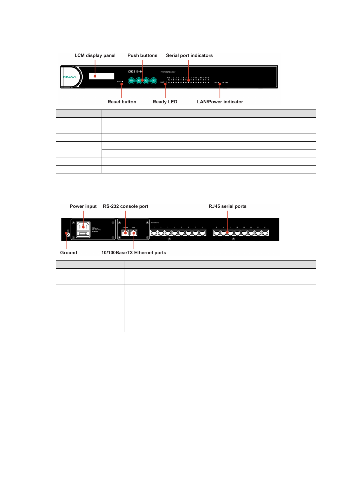
Front Panel
Feature Description
Reset Button Press the Reset button for 5 seconds to load factory defaults. CN2510 will beep twice when
the configuration has been reset.
Push Buttons Used for configuring the IP address and other parameters.
Ready LED Red Indicates that CN2510 is receiving power
Green Indicates that CN2510’s OS is ready
Serial Tx Green Indicates serial port transmission
Serial Rx Yellow Indicates serial port reception
Rear Panel
Socket / Port Description
AC Power Input CN2510-8 and CN2510-8:
DC Power Input CN2510-8-48V and CN2510-8-48V:
Power On/Off Switch I indicates power on; O indicates power off (AC models only)
Console 8-pin RJ45 RS-232 port for console terminal connection
LAN 8-pin RJ45 auto-detectable 10/100 Mbps UTP port
Serial Ports 8 or 16 8-pin RJ45 ports for DCE modem-type connections
Automatic detection of 100-240V, 47-63 Hz AC power supply
Automatic detection of 48 VDC or -48 VDC power supply
Page 9

2
2. Getting Started
This chapter includes instructions on where and how to install CN2510 Async Server. Both basic and advanced
software configuration instructions are given.
The following topics are covered in this chapter:
Hardware Installation
Desktop
Rackmount
Wiring Requirements
Connecting CN2510-8/16’s Power
Connecting CN2510-8/16-48V’s Power
Grounding CN2510-8/16-48V
Connecting to the Network
Connecting to a Serial Device
Connecting to the Console Port
Accessing the Console Utility
Configuration Checklist
Accessing the Console from a Telnet Terminal
Accessing the Console from a Console Terminal
Configuring CN2510—The Server Menu
Server Configuration—Info.
Server Configuration—LAN
Server Configuration—Adv.
Server Configuration—Host_table
Server Configuration—Route_table
Server Configuration—User_table
Save
Restart
Page 10
CN2510 Getting Started
2-2
ATTENTION
Safety First!
Be sure to disconnect the power cord before inst
Wiring Caution!
Calculate the maximum possible current in each power wire and common wire. Observe all electrical codes
dictating the maximum current allowable for each wire size.
If the current goes above the maximum rati
equipment.
Temperature Caution!
Be careful when handling CN2510. When plugged in, CN2510’s internal components generate heat, and
consequently the board may feel hot to the touch.
Hardware Installation
Desktop
Place your CN2510 on a clean, flat, well-ventilated desktop. For better ventilation, attach the 4 pads from the
desktop kit to the bottom of the unit, and leave some space between the CN2510 and other equipment. Do not
place equipment or objects on top of the unit, as this might damage the server.
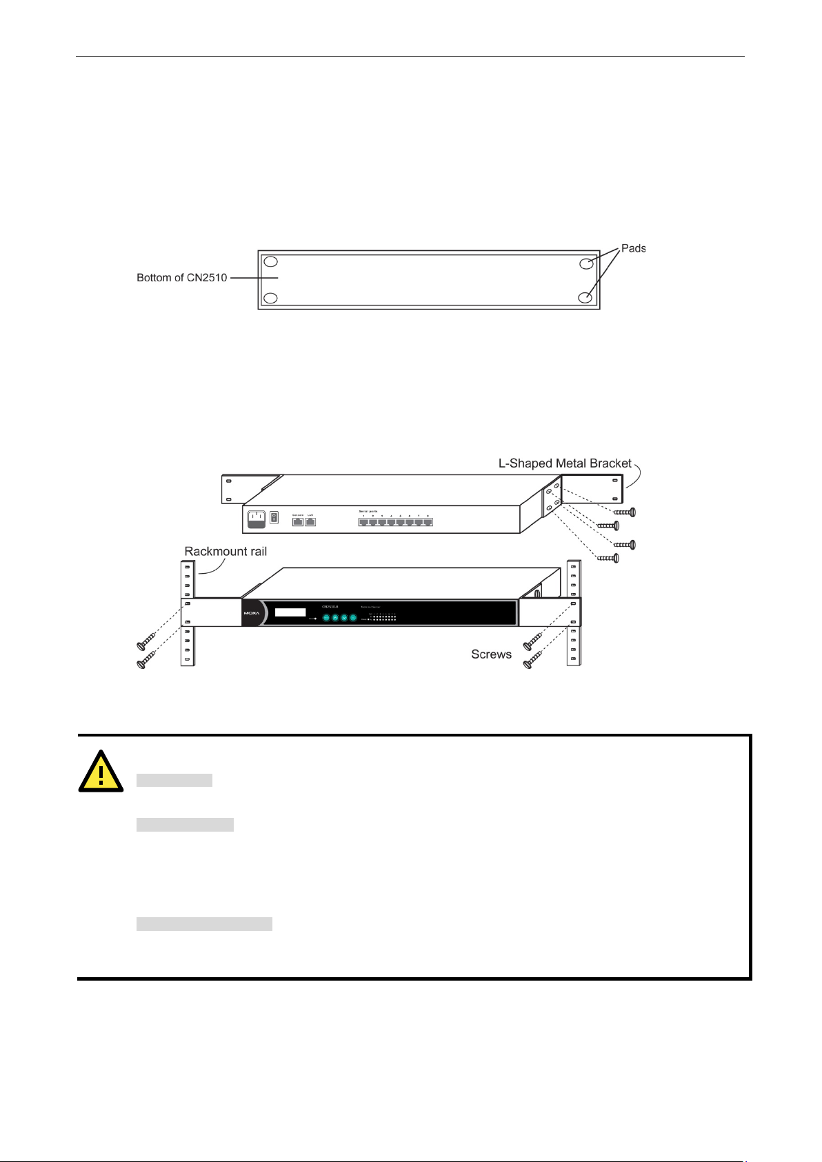
Rackmount
CN2510 is designed to be mounted on a standard 19-inch rack. Use the enclosed pair of L-shaped metal
brackets and screws to fasten your CN2510 to the rack cabinet. Each L-shaped bracket has 6 holes, leaving two
outer or inner holes available for other uses. You have two options. You can lock either the front or rear panel
of the CN2510 to the front of the rack. Locking the front panel is shown in the following figure.
Wiring Requirements
alling and/or wiring your CN2510.
ngs, the wiring could overheat, causing serious damage to your
Page 11

CN2510 Getting Started
2-3
terminal, and
48V and DC Power Ground
NOTE
Use 8 kg
terminal block.
Grounding and wire routing helps limit the effects of noise due to electromagnetic interference
(EMI).
connecting serial
ATTENTION
CN2510
You should also observe the following common wiring rules:
• Use separate paths to route wiring for power and devices. If power wiring and device wiring paths must
cross, make sure the wires are perpendicular at the intersection point.
NOTE: Do not run signal or communication wiring and power wiring in the same wire conduit. To avoid
interference, wires with different signal characteristics should be routed separately.
• You can use the type of signal transmitted through a wire to determine which wires should be kept separate.
The rule of thumb is that wiring that shares similar electrical characteristics can be bundled together.
• Keep input wiring and output wiring separate.
• Where necessary, it is strongly advised that you label wiring to all devices in the system.
Connecting CN2510-8/16’s Power
Connect CN2510’s 100-240 VAC power line to its AC connector. If the power is properly supplied, the “Ready”
LED will show a solid red color until the system is ready, at which time the color changes to green.
Connecting CN2510-8/16-48V’s Power
To connect CN2510-8/16-48V’s power cord to its terminal block, follow the steps given below:
Loosen the screws on the V+ and V- terminals of CN2510-8/16-48V’s terminal block.
Connect the power cord’s 48 VDC or -48 VDC wire to the terminal block’s V+
the power cord’s DC Power Ground wire to the terminal block’s V- terminal, and then
tighten the terminal block screws.
(Note: CN2510-8/16-48V will still operate properly if the 48V/-
wires are reversed.)
If the power is properly supplied, the “Ready” LED will show a solid red color until the system is ready, at which
time the color changes to green.
-cm of screw torque and 22-14 AWG electric wire to connect CN2510-8/16-48V’s power cord to its
Grounding CN2510-8/16-48V
Run the ground connection from the ground screw to the grounding surface prior to
devices to CN2510.
The Shielded Ground (sometimes called Protected Ground) contact is the second contact from the right of the
5-pin power terminal block connector located on the rear panel of CN2510-8/16-48V. Connect the SG wire to
the Earth ground.
-8/16-48V should be mounted to a well-grounded surface, such as a metal panel.
Page 12

CN2510 Getting Started
2-4
The top right
connected to a 100 Mbps Ethernet network.
The
connected to a 10 Mbps Ethernet network.
NOTE
If your network is already set up, telnet over the network to CN2510’s IP address to access the Console Utility.
If your network environment is not set up, use Moxa PComm Terminal to establish a direct serial console
connection.
Connecting to the Network
Connect one end of the Ethernet cable to CN2510’s 10/100M Ethernet port and the other end of the cable to the
Ethernet network. There are 2 LED indicators located on the top left and right corners of the Ethernet connector.
If the cable is properly connected, CN2510 will indicate a valid connection to the Ethernet in the following ways:
corner LED indicator maintains a solid green color when the cable is properly
top left corner LED indicator maintains a solid orange color when the cable is properly
Connecting to a Serial Device
Use appropriately wired serial data cables to connect serial devices to CN2510’s serial ports.
Connecting to the Console Port
A console is a combination of keyboard and monitor that is used to configure settings and monitor the status
of your system. The console port can be used if a network is unavailable, or you do not know CN2510’s IP
address. To connect to the console port, use a PC running UNIX, or a PC with terminal emulation software (e.g.,
HyperTerminal or PComm by Moxa; parameter settings are: baud rate = 115200 bps, parity check = None,
data bits = 8, stop bits = 1, terminal type = VT100). Use an RJ45-to-DB25 or RJ45-to-DB9 cable to connect the
terminal to the console port.
Accessing the Console Utility
The Console Utility is the main application used to set up the server, configure the ports, and run utilities (ping,
diagnosis, monitor, and upgrade). There are two ways to access the Console Utility—with terminal emulation
from a console terminal, or with Telnet from a network terminal.
Configuration Checklist
You will need the following information to configure CN2510. Check with your network administrator if you do
not know all of the required information.
Basic CN2510 Information:
Name
Location
LAN1 IP address
LAN1 IP netmask
LAN1 default gateway IP address
Domain server 1 IP address
Domain server 2 IP address
WINS server IP address
Console password
Page 13
CN2510 Getting Started
2-5
Accessing the Console from a Telnet Terminal
Connect CN2510 to your LAN and then turn on the power. Use the Moxa Windows Utility to find CN2510’s IP
address, and then telnet to the IP address to enter the CN2510 console.
CN2510 Windows Utility
The CN2510 Utility is a convenient Windows utility that can be used to find both the name and IP address of
your CN2510. Once you know the IP address, you can telnet CN2510 over the network to complete the
configuration process and to gather information about all servers on the network.
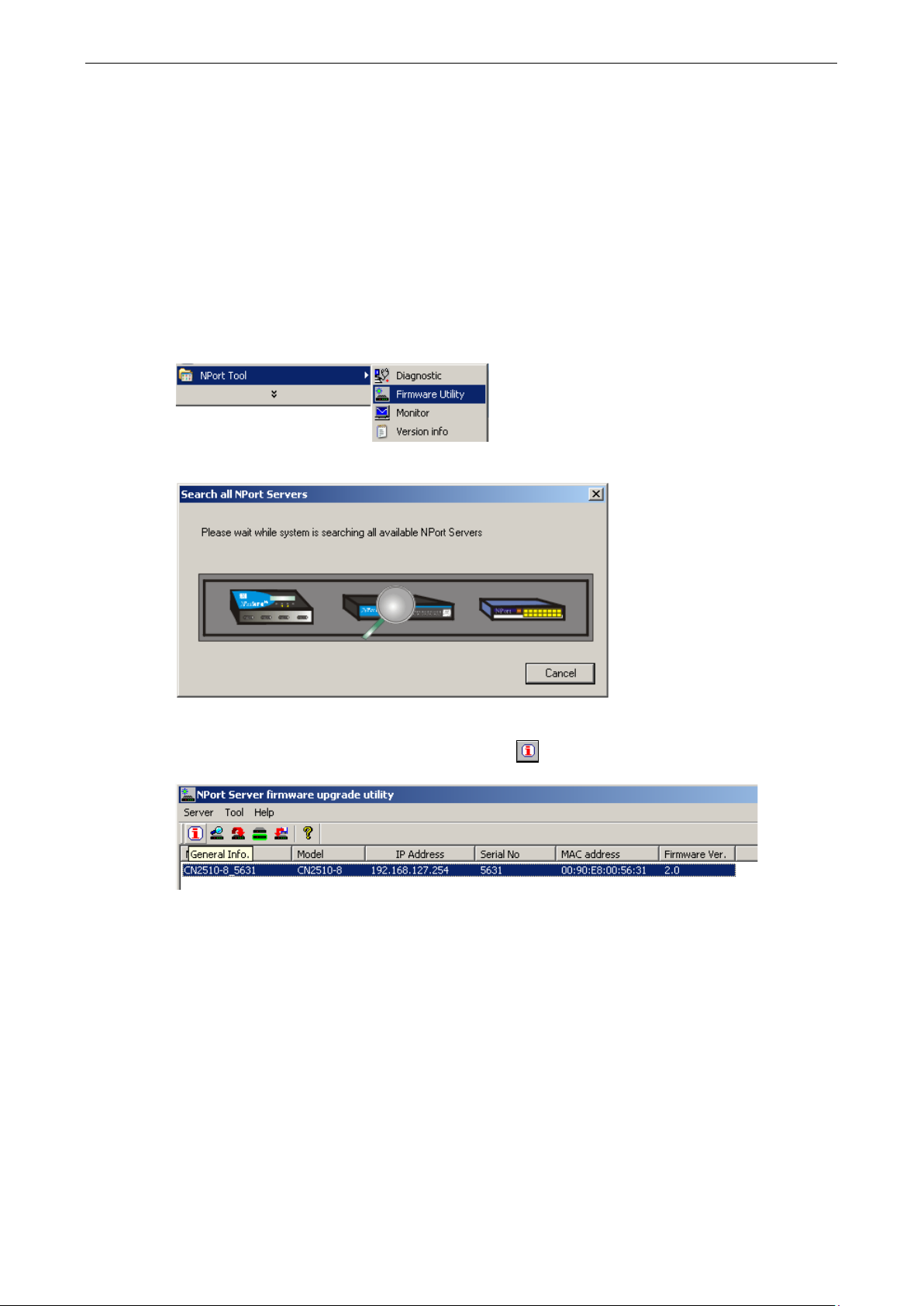
1. Run upgrade.exe, located in the \Software\Firmware\ folder on the CN2510 Documentation and Software
CD, or run NPort Tool Firmware Utility from the Start menu.
2. The CN2510 Utility will search for all CN2510s on the network.
3. The CN2510 Utility lists all available servers on the network. Note that servers in grey are password
protected. Double click the server’s name, or click on from the menu bar to see the server settings.
Page 14
CN2510 Getting Started
2-6
Telnet 192.168.127.254
Telnet 192.168.127.254
CN2510-8 CN2510-8_5631 V2.0 MAIN MENU
------------------
[Server]
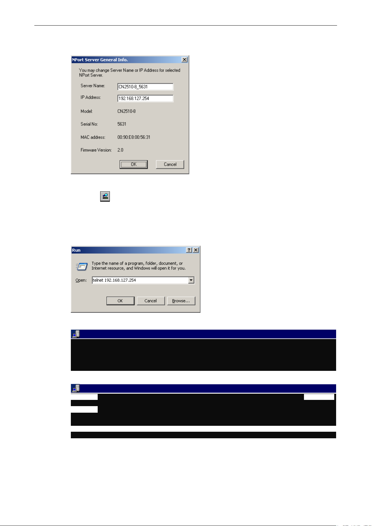
4. The server’s general information is shown in the NPort Server General Info. window. If necessary,
change the settings, and then click on OK to accept the change.
5. If you can’t find the server in the list, double-check the server’s power and network connections, and then
use search
to try locating the server again.
Using Telnet
1. Telnet over the network to the server’s IP address.
2. Type 1 to choose ansi/vt100, and then press Enter.
Async Server CN2510-8
Console terminal type (1: ansi/vt100, 2: vt52) : 1
3. CN2510’s MAIN MENU will open, as shown below.
------------------------------------------------------------
Port seTting sAve Utility Restart Exit
Examine/modify async server node/table configuration
Enter: select ESC: previous menu
Page 15
CN2510 Getting Started
2-7
Use the following keystrokes to navigate CN2510’s console utility.
Action Key
Move [Up/Down/Left/Right] Arrow Key or [Tab] Key
Jump to next menu, or
Select item
Return to previous menu, or
Close pop up selector
Shortcut Key Capitalized letter of the word
[Enter] Key
[Esc] Key
Accessing the Console from a Console Terminal
If you do not know the CN2510’s IP address, or it is not possible to use Telnet, you can use a direct console
connection to enter the CN2510 console. Use a terminal emulation program for the console PC, such as
HyperTerminal or Moxa PComm Terminal Emulator.
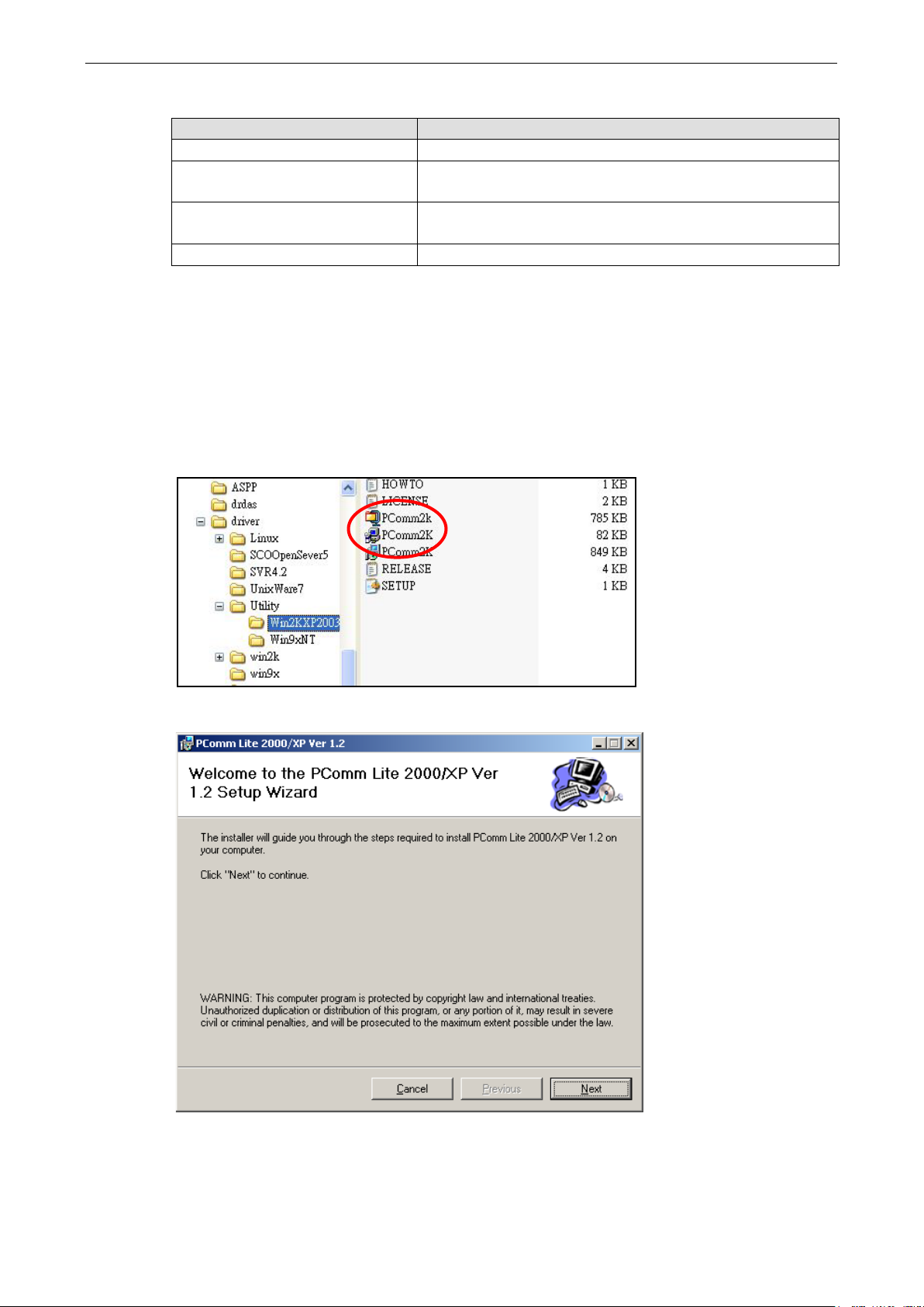
1. If you are using Windows 9x/ME/NT, run PComm26.exe from the Win9xNT directory. If you are using
Windows 2000/XP/2003, run PComm2K.exe , as shown in the figure below, from the
Win2kXP2003directory.
2. Click on Next to Continue.
Page 16
CN2510 Getting Started
2-8
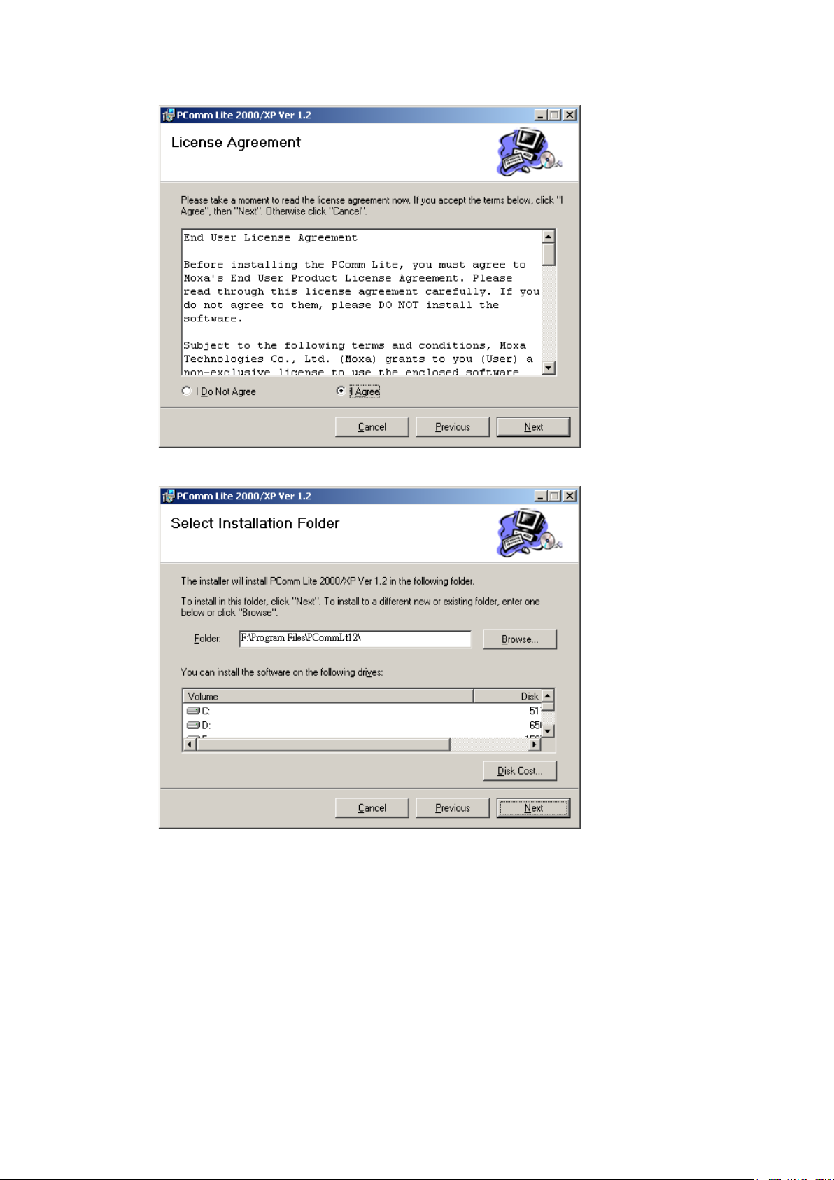
3. Select the I Agree option and then click on Next.
4. Select a directory in which to install the CN2510 Utility, and then click on Next.
Page 17
CN2510 Getting Started
2-9
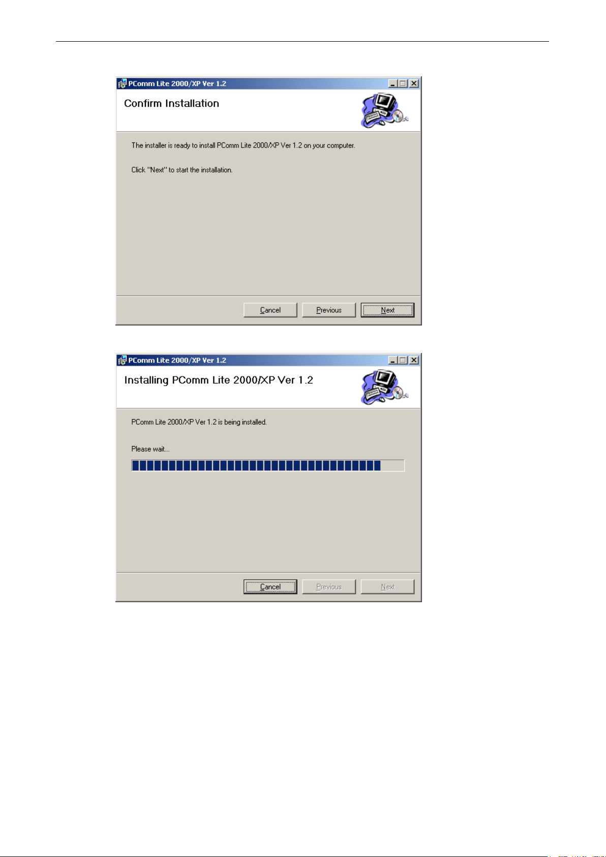
5. Click on Next to continue.
6. Wait while the PComm Lite software is installed.
Page 18
CN2510 Getting Started
2-10
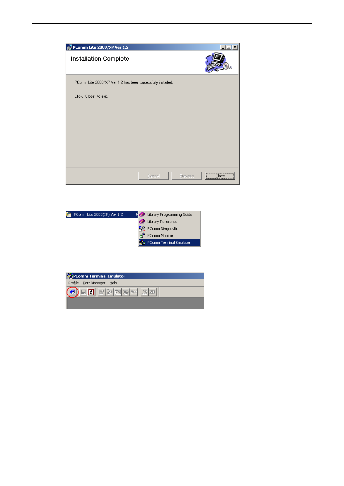
7. Click on Close.
8. When the installation is complete, select Start Programs PComm Terminal Emulator to run
PComm Terminal Emulator.
9. Use an RJ45 to DB25 female cable to connect to the CN2510 console port. Start PComm Terminal, and then
click on the left-most icon to open a new connection.
Page 19
CN2510 Getting Started
2-11
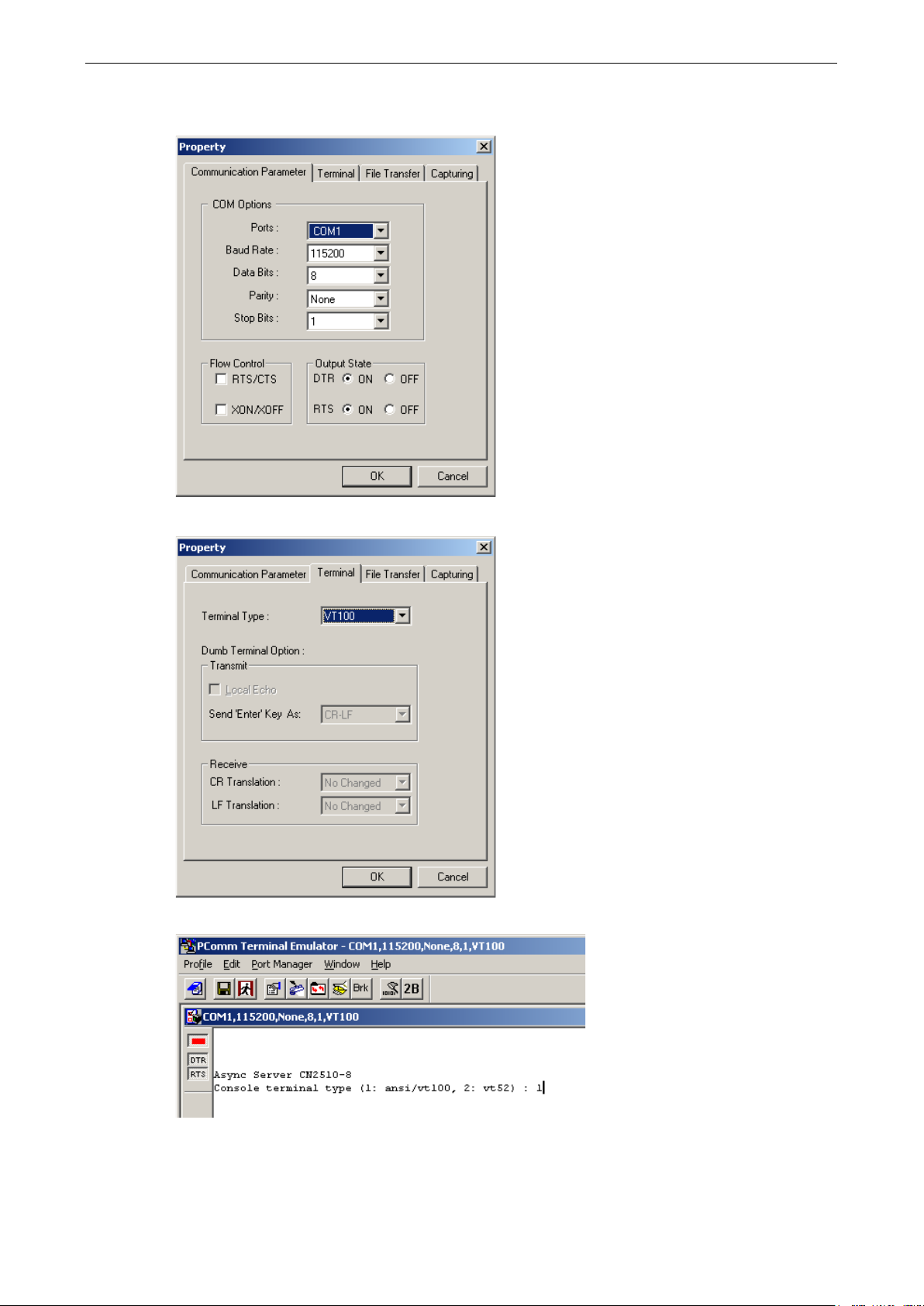
10. Click on the Communication Parameter tab, select the COM port (COM2 in this example) for console
connection, 115200 for Baud Rate, 8 for Data Bits, None for Parity, and 1 for Stop Bits.
11. Click on the Terminal tab and select VT100 for terminal type. Press Enter to confirm.
12. Type 1 to select ansi/VT100 terminal type, and then press Enter to open the MAIN MENU.
Page 20

CN2510 Getting Started
2-12
CN2510-8 CN2510-8_5631 V2.0 MAIN MENU
------------------------------------------------
[Server]
CN2510-8 CN2510-8_5631 V2.0 SERVER MENU
--------------------------------------------------------
[Info.
CN2510-8 CN2510-8_5631 V2.0
----------------------------------------------------------
[Info.
13. The MAIN MENU is shown below. (NOTE: Click on Edit Font to choose a different font for the MAIN
MENU.)
Configuring CN2510—The Server Menu
In this section, we describe both basic and advanced configuration tasks. We use the Telnet interface to
illustrate (the Serial Console interface is the same).
Server Configuration—Info.
1. From the MAIN MENU, use the arrow keys to select Server, and then press Enter.
------------------------------
Port seTting sAve Utility Restart Exit
Examine/modify async server node/table configuration
Enter: select ESC: previous menu
2. From the SERVER MENU, select Info., and then press Enter.
----------------------
] Lan Adv. Host_table Route_table User_table Quit
Examine/modify async server basic configuration
Enter: select ESC: previous menu
3. The Info. page contains input/display fields for name, location, serial number, Domain server 1/2 IP
address, WINS function disable, WINS server IP address, and Console password. Each item is
described in detail below.
--------------------
] Lan Adv. Host_table Route_table User_table Quit
Examine/modify async server basic configuration
ESC: back to menu Enter: select
Async server name [CN2510-8_5631 ]
Async server location [ ]
Async server serial number [9]
Domain server 1 IP address [ ]
Domain server 2 IP address [ ]
WINS function disable [no ]
WINS server IP address [ ]
Console password [ ]
Page 21

CN2510 Getting Started
2-13
NOTE
Write your console password in a safe place before setting the password.
CN2510-8 CN2510-8_5631 V2.0 MAIN MENU
------------------------------------------------
[Server]
CN2510-8 CN2510-8_5631 V2.0 SERVER MENU
--------------------
Async server name—CN2510 uses this name to identify itself when requested by an SNMP station or UNIX
host. Use an ASCII string with maximum length of 40 characters for the name. Spaces are allowed.
Async server location—CN2510 reports this location to the SNMP station when requested. Use an ASCII
string with maximum length of 44 characters for the location. Spaces are allowed.
Async server serial number—Each CN2510 Async Server is assigned a unique serial number before it
leaves the factory. The serial number cannot be changed.
Domain server 1/2 IP address—A Domain Name Server is a network host that translates host names to
IP addresses. Hosts use the Domain Name Server to request the IP address that corresponds to a particular
url (such as www.moxa.com
server 1 IP address field, and the IP address of the secondary Domain Name Server in the Domain
server 2 IP address field. When CN2510 receives a connection request, CN2510 first checks the host
table defined on the Host_table page. If a matching entry cannot be found, CN2510 sends a query to the
Domain Name Server.
WINS function disable—Enable or disable the WINS server. The default setting is “enable.”
WINS server IP address—If a WINS Server is connected to the network, use this field to record the WINS
Server’s IP address. TCP/IP uses IP addresses to identify hosts, but users often use symbolic names, such
as computer names. The WINS (Windows Internet Naming Service) Server, which uses NetBIOS over
TCP/IP, contains a dynamic database to map computer names to IP addresses.
). Input the IP address of the primary Domain Name Server in the Domain
Console password—If you specify a password, write it down for safe keeping. If you forget the password,
you will need to use the reset password button to reset it. Only use the console password when absolutely
necessary.
Server Configuration—LAN
1. From the MAIN MENU, use the arrow keys to select Server, and then press Enter.
Port seTting sAve Utility Restart Exit
Examine/modify async server node/table configuration
Enter: select ESC: previous menu
2. From the SERVER MENU, select Lan, and then press Enter.
---------------------------------------------------------Info. [Lan] Adv. Host_table Route_table User_table Quit
Examine/modify async server basic configuration
Enter: select ESC: previous menu
------------------------------
Page 22

CN2510 Getting Started
2-14
CN2510-8 CN2510-8_5631 V2.0
--------------------------------------------------
CN2510-8 CN2510-8_5631 V2.0 MAIN MENU
------------------------------------------------
[Server]
CN2510-8 CN2510-8_5631 V2.0 SERVER MENU
-------------------------------------------------------Info. Lan
3. The Lan page contains input/display fields for DHCP (client), Async server IP address, Async server
IP netmask, Default gateway IP address, Ethernet speed, and Ethernet address. Each item is
described in detail below.
---------------------------Info. [Lan] Adv. Host_table Route_table User_table Quit
Examine/modify the Ethernet LAN port setting
ESC: back to menu Enter: select
Ethernet LAN port 1:
DHCP (client) [Disable]
Async server IP address [192.168.127.254]
Async server IP netmask [255.255.255.0 ]
Default gateway IP address [ ]
Ethernet speed [ ---- ]
Ethernet address [00:90:E8:26:10:09]
DHCP (client)—When DHCP is enabled, CN2510 will request an available IP address and Netmask over the
network from the DHCP Server. If an IP address is not available, CN2510 will use the current IP address, but
will continue sending requests to the DHCP Server.
Async server IP address—This field MUST contain an IP address unique to the network. The IP address
is written using the notation “ddd.ddd.ddd.ddd,” in which each “ddd” is a nonnegative decimal number
strictly less than 256 (i.e., an 8-bit integer). The default value is 192.168.127.254.
Async server IP netmask—A netmask is used to group network hosts into subnets. CN2510 sends TCP/IP
packets directly to hosts that are on the same subnet. If the recipient of the packet is NOT on the same
subnet, the packet is sent to the default gateway IP address.
Default gateway IP address—This field contains the IP address of a router on the local network. The
default gateway is used when a packet is sent to an IP address that is not on the subnet specified in
CN2510’s local routing table.
Ethernet speed—If the Ethernet port is active, the Ethernet speed will be set automatically to 10BaseT or
100BaseT. This field cannot be modified.
Ethernet address—This field contains the hardware Ethernet address. This field cannot be modified.
Server Configuration—Adv.
1. From the MAIN MENU, use the arrow keys to select Server, and then press Enter.
Port seTting sAve Utility Restart Exit
Examine/modify async server node/table configuration
Enter: select ESC: previous menu
2. From the SERVER MENU, select Adv., and then press Enter.
------------------------------
----------------------
[Adv.] Host_table Route_table User_table Quit
Examine/modify async server basic configuration
Enter: select ESC: previous menu
Page 23

CN2510 Getting Started
2-15
CN2510-8 CN2510-8_5631 V2.0
--------------------------------------------------
3. The Adv. page contains input/display fields for RADIUS server IP, RADIUS key, UDP port, Enable
RADIUS accounting, SNMP community name, SNMP trap server IP address, Ethernet IP
forwarding, Routing protocol, TCP retransmission timeout, and SIO data transfer timeout. Each
item is described in detail below.
---------------------------Info. Lan [Adv.] Host_table Route_table User_table Quit
Examine/modify async server advance configuration
ESC: back to menu Enter: select
Radius server IP [ ]
RADIUS key [ ]
UDP port (1:1645 2:1812) [1]
Enable RADIUS accounting [no ]
SNMP community name [public ]
SNMP trap server IP address [ ]
Ethernet IP forwarding [no ]
Routing protocol [None ]
TCP retransmission timeout [ ] (range: 50 – 60000 ms)
SIO data transfer timeout [ ] (range: 0 – 1000 ms)
RADIUS server IP—The IP address of the RADIUS (Remote Authentication Dial-In User Service) server is
used to authenticate remote dial-in users connecting from an ISP (Internet Service Provider). Leave this
field blank if you do not have a RADIUS server on your network.
Windows NT includes RADIUS software. For UNIX-based platforms, refer to Appendix B for information
about setting up a RADIUS server.
NOTE: The RADIUS server and CN2510 SHOULD be able to communicate with each other. To verify this,
check to see if you can ping from each server to the other.
RADIUS server IP—This is the IP address of the RADIUS server.
RADIUS key—This is a shared key used by the RADIUS protocol. If you have a RADIUS server, you will
need to enter the password in this field.
UDP port (1:1645 2:1812)—RADIUS originally used port 1645, but more recently this conflicted with the
RFC standard, so the officially assigned RADIUS port is now 1812. Check which UDP port your RADIUS
server software uses to determine the proper choice.
Enable RADIUS accounting—The default for this field is no. If your RADIUS Server offers this function,
set it to yes.
SNMP community name—The SNMP community name can be used to guarantee minimal security for
SNMP communication. Only SNMP stations with the same community name can access SNMP agents (such
as Async Server). Choose a community name with no more than 16 ASCII characters. The default name is
“public.”
SNMP trap server IP address—This field specifies the IP address of the SNMP trap server. CN2510 will
report to the SNMP trap server each time it restarts. You may leave this field blank if SNMP is not needed.
Ethernet IP forwarding—CN2510 can forward packets between different segments of a TCP/IP network.
When enabled, CN2510 will use its Ethernet routing ability to identify which incoming packets should be
forwarded.
Routing protocol—CN2510 supports RIP (Routing Information Protocol) versions 1 and 2, a widely used
protocol specifying how routers exchange routing table information. When RIP is activated, routers (or
CN2510s) periodically exchange entire routing tables.
TCP retransmission timeout—This is the amount of time CN2510 waits to retransmit after a transmission
failure occurs.
Page 24

CN2510 Getting Started
2-16
CN2510-8 CN2510-8_5631 V2.0 MAIN MENU
-------------------------
[Server]
CN2510-8 CN2510-8_5631 V2.0 SERVER MENU
-------------------------------------------------------Info. Lan Adv.
CN2510-8 CN2510-8_5631 V2.0
--------------------------------------------------
08 [ ] [ ]
CN2510-8 CN2510-8_5631 V2.0 MAIN MENU
------------------------------------------------
[Server]
CN2510-8 CN2510-8_5631 V2.0 SERVER MENU
-------------------------------------------------------Info. Lan Adv. Host_table
SIO data transfer timeout—This is the amount of time (in milliseconds) CN2510 waits to send serial data
to the Ethernet. Use a shorter timeout to improve efficiency.
Server Configuration—Host_table
1. From the MAIN MENU, use the arrow keys to select Server, and then press Enter.
-----------------------------------------------------
Port seTting sAve Utility Restart Exit
Examine/modify async server node/table configuration
Enter: select ESC: previous menu
2. From the SERVER MENU, select Host_table, and then press Enter.
----------------------
[Host_table] Route_table User_table Quit
Examine/modify async server basic configuration
Enter: select ESC: previous menu
3. The Host_table contains frequently accessed host names and their corresponding IP addresses. Adding
entries to this table gives you the advantage of being able to refer to a host by name, instead of by IP
address. The host table can hold up to 16 [Host name] / [Host IP address] entries. The Host_table page
contains input/display fields for Entry, Host name, and Host IP address.
Info. Lan Adv. [Host_table] Route_table User_table Quit
Examine/modify the host table
ESC: back to menu Enter: select
Entry Host name Host IP address
01 [ ] [ ]
02 [ ] [ ]
03 [ ] [ ]
04 [ ] [ ]
05 [ ] [ ]
06 [ ] [ ]
07 [ ] [ ]
Server Configuration—Route_table
1. From the MAIN MENU, use the arrow keys to select Server, and then press Enter.
Port seTting sAve Utility Restart Exit
Examine/modify async server node/table configuration
Enter: select ESC: previous menu
----------------------------
------------------------------
2. From the SERVER MENU, select Route_table, and then press Enter.
----------------------
[Route_table] User_table Quit
Examine/modify async server basic configuration
Enter: select ESC: previous menu
Page 25

CN2510 Getting Started
2-17
CN2510-8 CN2510-8_5631 V2.0
--------------------------------------------------
08 [ ] [ ] [ ] [01]
CN2510-8 CN2510-8_5631 V2.0 MAIN MENU
------------------------------------------------
[Server]
CN2510-8 CN2510-8_5631 V2.0 SERVER MENU
-------------------------------------------------------Info. Lan Adv. Host_table
CN2510-8 CN2510-8_5631 V2.0
--------------------------------------------------
08 [ ] [ ] [ ]
3. The Route_table specifies routing parameters. The Route_table page contains input/display fields for
Entry, Gateway, Destination, Netmask, and Metric. Each item is described in detail below.
--------------------Info. Lan Adv. Host_table [Route_table] User_table Quit
Examine/modify the routing table
ESC: back to menu Enter: select
Entry Gateway Destination Netmask Metric
01 [ ] [ ] [ ] [01]
02 [ ] [ ] [ ] [01]
03 [ ] [ ] [ ] [01]
04 [ ] [ ] [ ] [01]
05 [ ] [ ] [ ] [01]
06 [ ] [ ] [ ] [01]
07 [ ] [ ] [ ] [01]
Gateway—The gateway IP address or interface source IP address to which data packets are sent.
Destination—The IP address of a host or network to which the route connects.
Netmask—The netmask of the destination network.
Metric—The number of hops from source to destination. Refer to Chapter 14 for routing settings.
Server Configuration—User_table
1. From the MAIN MENU, use the arrow keys to select Server, and then press Enter.
Port seTting sAve Utility Restart Exit
Examine/modify async server node/table configuration
Enter: select ESC: previous menu
2. From the SERVER MENU, select User_table, and then press Enter.
Route_table [User_table] Quit
Examine/modify async server basic configuration
Enter: select ESC: previous menu
3. The User_table is used for local authentication for dial-in/out access. The CN2510 User Table, which holds
information for up to 64 users, is useful if you do not have an external RADIUS server for authentication.
The User_table page contains input/display fields for Entry, User name, Password, and Phone
number.
Info. Lan Adv. Host_table Route_table [User_table] Quit
Examine/modify the user/password table
------------------------------
----------------------
----------------------------
ESC: back to menu Enter: select
Entry User name Password Phone number
01 [ ] [ ] [ ]
02 [ ] [ ] [ ]
03 [ ] [ ] [ ]
04 [ ] [ ] [ ]
05 [ ] [ ] [ ]
06 [ ] [ ] [ ]
07 [ ] [ ] [ ]
Page 26

CN2510 Getting Started
2-18
CN2510-8 CN2510-8_5631 V2.0 MAIN MENU
--------------------------
CN2510-8 CN2510-8_5631 V2.0
------------------------------------------------
CN2510-8 CN2510-8_5631 V2.0 MAIN MENU
--------------------------------------------------
CN2510-8 CN2510-8_5631 V2.0
--------------------------------------------------
[System]
ESC
Save
When exiting the SERVER MENU, you will be prompted to save settings. Press Y to save.
---------------------------------------------------Info. Lan Adv. Host_table Route_table [User_table] Quit
Examine/modify async server basic configuration
Enter: select ESC: previous menu
+------------------------------------------------------+
| Warning !!! |
| You had modified the configuration without saving. |
| Would you save it now ? |
| ‘Y’: yes ‘N’: no |
+------------------------------------------------------+
You may also save all settings from the MAIN MENU by selecting sAve.
-----------------------------Server Port seTting [sAve] Utility Restart Exit
Save current configuration to Flash ROM
ESC: back to menu Enter: select
+-------------------------------------+
|Enter to updated, other key to cancel|
+-------------------------------------+
Restart
1. From the MAIN MENU, select Restart.
Server Port seTting sAve Utility [Restart] Exit
Restart the whole system or selected async ports
Enter: select ESC: previous menu
2. Select System and then press Enter to restart the system and terminate the Telnet session.
Restart the Async Server
----------------------------
----------------------------
Port Quit
: back to menu Enter: select
+----------------------------------------------------------------------+
| Warning !!! |
| Restart system will disconnect all ports and clear all status value |
| ‘ Enter: continue ESC: cancel |
+----------------------------------------------------------------------+
Page 27

3
3. Knowing Your Application
This chapter discusses a variety of applications for CN2510 Async Server. Refer to the diagrams in each section
to see which application most closely matches your own. Determining which application you should choose will
save time configuring both the hardware and software.
CN2510 is an Async Server that can support simultaneously different operation modes for different serial ports.
The examples in this chapter explain each operation mode in detail. You can create a wide variety of
applications by using different combinations of operation modes on the same Async Server.
NOTE: Each section title consists of an application name that uses terminology common to our industry,
followed in parentheses by the application name used in CN2510’s console utility. For example, the CN2510
application that corresponds to Linux Real TTY/Unix Fixed TTY is NT Real COM mode.
The following topics are covered in this chapter:
Windows Real COM (NT Real COM)
Linux Real TTY/Unix Fixed TTY (NT Real COM)
Device Control (Device Control)
UDP Communication (Raw UDP)
Console Management (Reverse Terminal)
Terminal Access (Terminal)
Multi-host TTY (Multi-host TTY)
Dial-in/Out-of-Band Management (Dialin/out)
Network Printer (Printer)
Multiplexor Access (Multiplex)
Page 28
CN2510 Knowing Your Application
3-2
s
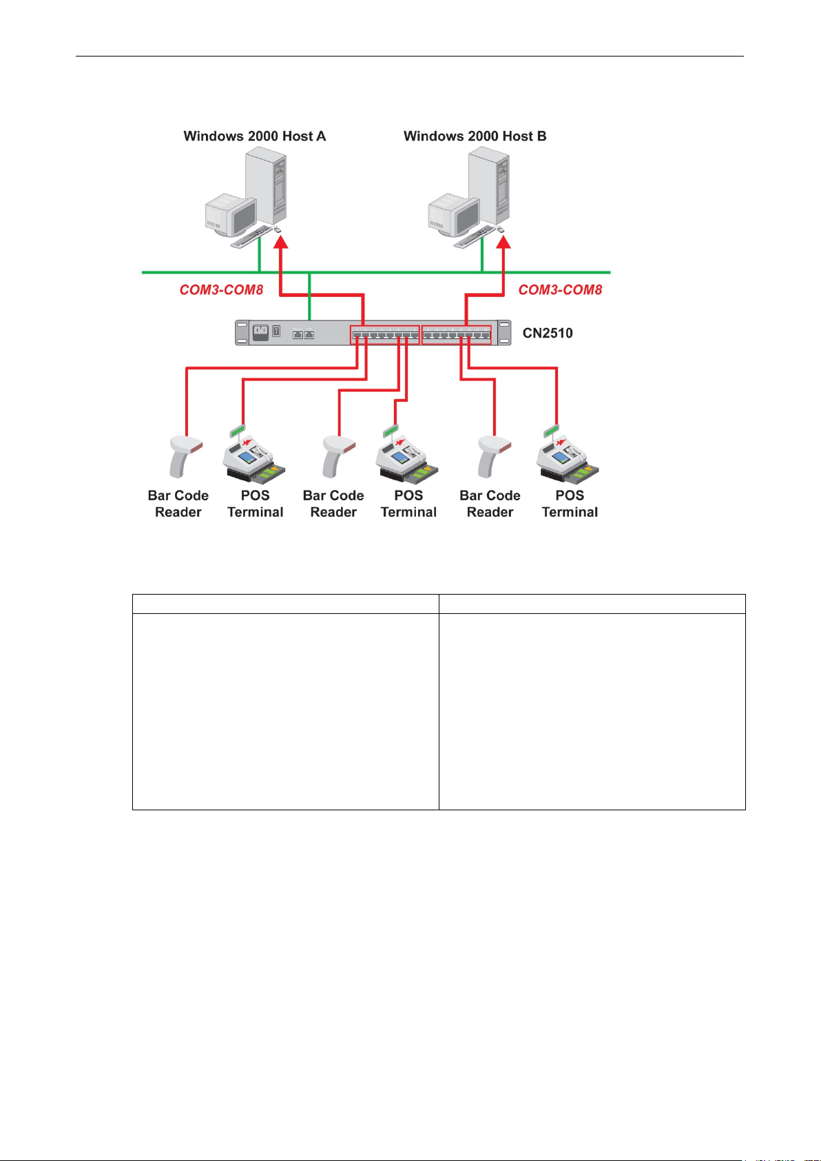
Windows Real COM (NT Real COM)
Moxa provides CN2510 COM port drivers for all Windows operating systems. The COM port driver serves a dual
purpose—(1) convert serial data into Ethernet packets, (2) convert Ethernet packets into serial data—as
outlined in the following table:
PC CN2510 Serial Device Serial Device CN2510 PC
1. The PC generates RS-232 serial COM commands.
2. The COM port driver converts the commands
into Ethernet packets.
3. The packets are sent over the network to CN2510’
Ethernet port.
4. CN2510 converts the Ethernet packets back into
RS-232 serial format.
5. The commands are delivered to serial device(s)
connected to CN2510’s serial port(s).
You can enhance your applications greatly by using CN2510 to access serial devices over an Ethernet network,
and since CN2510 and the COM driver handle all protocol conversion tasks, you won’t need to modify the
software currently in use. In fact, multiple PCs can access the serial ports of one CN2510, as shown in the
figure.
Refer to Chapter 4 for detailed information and configuration instructions.
1. A serial device connected to CN2510 starts
transmitting serial data.
2. CN2510 converts the data into one or more
Ethernet packets.
3. The packets are sent over the network to the PC
host’s Ethernet port.
4. The COM port driver converts the Ethernet
packets back into RS-232 serial format.
5. The serial data is processed by the program that
controls the serial device.
Page 29
CN2510 Knowing Your Application
3-3
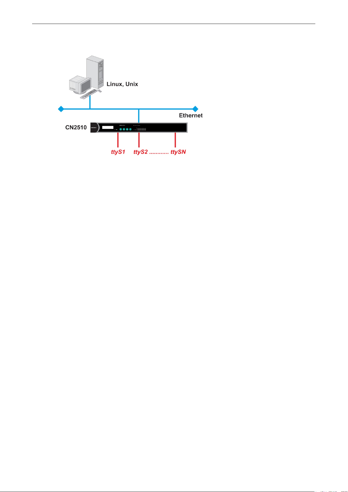
Linux Real TTY/Unix Fixed TTY (NT Real COM)
Real TTY drivers that control Moxa CN2510 Async Server’s serial ports are provided for Linux environments.
This means that CN2510 Async Server can be used with existing Linux-based applications that use multiport
serial boards, since the host PC will recognize CN2510’s COM ports as real TTY ports. You can enhance your
applications by using CN2510 to access serial devices over an Ethernet network, but without needing to modify
the software currently in use.
Moxa also provides Fixed TTY port drivers for Unix environments. However, the Linux Real TTY and Windows
Real COM port drivers provide better control over serial port data transmission, since you can control modem
signals such as DTR, DSR, RTS, and CTS. The Unix Fixed TTY driver provides software reception and
transmission through CN2510’s serial ports, but does not allow you to control the DTR, DSR, RTS, and CTS
modem signals.
Refer to Chapter 4 for detailed information and configuration instructions.
Page 30
CN2510 Knowing Your Application
3-4
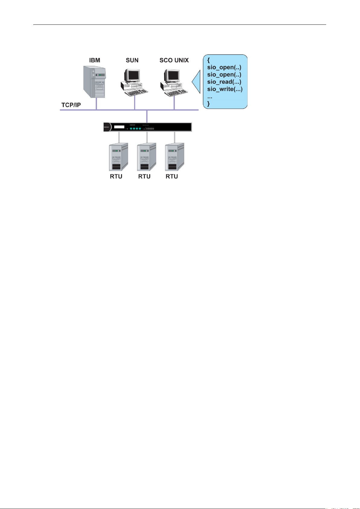
Device Control (Device Control)
The CN2510 Device Control application allows you to choose between two different operation modes: ASPP and
RAW.
ASPP Mode—For applications that require setting up communication parameters or controlling modem signals
(DTR, RTS, Break, etc.), take advantage of Moxa’s ASPP lib to simplify your programming tasks. ASPP takes
care of the more basic protocol-level programming tasks, and allows you to concentrate your energy on higher
level, application-specific tasks.
RAW Mode—To control device data transmission directly, set CN2510 for TCP RAW mode. Device control
applications can use standard Linux/Unix Socket programming in Linux/Unix environments, or WinSock
programming in Windows environments. Standard socket programming allows you to focus on pure data
transmission, without needing to write code for controlling serial ports or modem signals. ASPP can also be
used to communicate with CN2510.
Linux/Unix socket programming and Windows WinSock programming both use IP as the communication agent
between hosts and devices. RAW mode is a good solution for handling pure serial data communications
applications that do not require setting up communication parameters (baud rate, parity, etc.).
Refer to Chapter 5 for detailed information and configuration instructions.
Page 31

CN2510 Knowing Your Application
3-5
UDP Communication (Raw UDP)
UDP is a non connection-oriented data transmission protocol that has the advantages of efficient, high-speed,
high-volume data transmission. Since UDP does not use TCP’s handshaking procedure, it does not re-assemble
and retransmit packets when data is missing. This means that data integrity is sacrificed for higher
transmission speed. UDP provides a very powerful transmission method when data needs to be transmitted
quickly over the network, and upper-level application software is given the responsibility of verifying the
accuracy of the data.
UDP can also use broadcasting or multicasting technologies to handle point to multi-point transmissions. UDP
is an ideal transmission method for serial devices that must transmit data to a group of devices or PCs.
Refer to Chapter 6 for detailed information and configuration instructions.
Page 32

CN2510 Knowing Your Application
3-6
Console Management (Reverse Terminal)
The Reverse Terminal application, which uses Rtelnet mode, is used with routers, switches, and UPS equipment
for console management applications. Rtelnet mode is similar to RAW mode, in that after booting up it listens
to one specific TCP port for network hosts to initiate a connection. RAW mode, however, does not provide a
Telnet conversion function. If the serial devices connected to CN2510 need to use the CR/LF conversion
function, then Rtelnet mode must be used. CN2510’s Rtelnet mode is also used widely for device management
applications in telecommunication control rooms, since remote hosts can make use of Local User Table or
RADIUS identity verification methods.
Refer to Chapter 7 for detailed information and configuration instructions.
Page 33

CN2510 Knowing Your Application
3-7
Terminal Access (Terminal)
CN2510’s Terminal Access application is used to connect terminals to Unix or Windows Servers over a network.
The terminals connect to CN2510’s serial ports at a remote site, with terminal commands transmitted over the
network via CN2510’s Ethernet port. The Terminal Access application allows you to use fast keys used in many
terminal applications, and switching sessions on the same terminal. CN2510 supports ASCII terminal and
Binary terminal, with up to 8 simultaneous sessions for each port.
Refer to Chapter 8 for detailed information and configuration instructions.
Page 34

CN2510 Knowing Your Application
3-8
Multi-host TTY (Multi-host TTY)
The Multi-host TTY application is ideal for connecting over a network to multiple Unix hosts from several
sessions simultaneously. When communication begins, the networked Unix server must first enable Moxattyd
to activate the TTY port’s mapping function. Moxattyd will initiate the connection with the CN2510, and the
CN2510 will listen to the connection requests issued by various Moxattyd over different TCP ports.
Once the connection is established, the Terminal server can use hot keys to switch sessions, allowing one
terminal to control different Unix hosts.
Refer to Chapter 9 for detailed information and configuration instructions.
Page 35

CN2510 Knowing Your Application
3-9
Dial-in/Out-of-Band Management (Dialin/out)
Moxa CN2510 Async Server provides dial-up/dial-out access for ISPs and enterprises that need a remote
access solution. When a user at a remote site uses a PPP dial-up connection to access CN2510, CN2510 plays
the role of dial-up server, but also ensures the user has legal access to the network by verifying the user’s
identity with its Local User Table or RADIUS.
CN2510 supports PPP, SLIP, and Terminal modes for dial-up/dial-out access. Regardless of which OS is used,
you will always be able to use standard PPP dial-up to establish a connection. CN2510 can also act as an Async
router to connect serial ports to a WAN connection. Routing protocols (including static, RIP I, and RIP II) can
be adjusted to route different WAN connections.
Refer to Chapter 10 for detailed information and configuration instructions.
Page 36

CN2510 Knowing Your Application
3-10
Network Printer (Printer)
CN2510 Async Server’s printing program (running under UNIX) provides an excellent solution for banking and
stock exchange services with huge printing demands. Use a Windows or Unix host’s network printer function
via RAW mode, and assign a specific IP address and TCP port number to specify the printer’s location. You can
also connect to the printer via LPD mode when LPD protocol is needed to operate the printer.
Refer to Chapter 11 for detailed information and configuration instructions.
Page 37

CN2510 Knowing Your Application
3-11
NOTE
Multiplexor Access (Multiplex)
If are using a multiport serial board installed in a UNIX host, but wish to extend the device control range without
dismantling the host, you can accomplish this with CN2510. Multiplex and De-multiplex solutions use CN2510’s
RTelnet and terminal modes, eliminating the need to modify existing software. CN2510 acts like a converter by
extending the communication distance. CN2510s work in pairs over the network to overcome the short
communication distance limitation imposed by serial connections.
See Chapter 12 for detailed configuration instructions.
This mode does not allow copying the status of control signals to devices at a remote site.
Page 38

4
4. Setting Up Windows Real COM/Linux Real
TTY/Unix Fixed TTY
CN2510 Async Server supports Real COM/TTY drivers for Windows and Linux, allowing CN2510’s serial ports to
be recognized as Real COM ports by the Windows operating system, or Real TTY ports by Linux operating
systems. CN2510 Async Server can be used for a variety of applications to make the serial ports accessible over
an Ethernet, but without the need to modify existing serial transmission software. The Real COM driver
provided by Moxa lets users treat networked serial ports the same as local serial ports.
The following topics are covered in this chapter:
Accessing the Console Utility
Selecting the Application
Configuring ASPP Mode
Configuring the Serial Ports
Save
Restart
Setting up Hosts
Setting up Windows XP/2003 Hosts
Setting up Windows 2000 Hosts
Setting up Windows 95/98/ME/NT Hosts
Page 39

CN2510 Setting Up Windows Real COM/Linux Real TTY/Unix Fixed TTY
4-2
NOTE
In this section, we show how to access CN2510’s console utility by Telnet over the network. For information on
using the console port, see the section “Accessing the Console Utility” in Chapter
Telnet 192.168.127.254
Telnet 192.168.127.254
CN2510-8 CN2510-8_5631 V2.0 MAIN MENU
------------------
[Server]
Select item
CN2510-8 CN2510-8_5631 V2.0 MAIN MENU
------------------------------------------------
Accessing the Console Utility
2.
1. Telnet over the network to the server’s IP address.
2. Type 1 to choose ansi/vt100, and then press Enter.
Async Server CN2510-8
Console terminal type (1: ansi/vt100, 2: vt52) : 1
3. CN2510’s MAIN MENU will open, as shown below.
------------------------------------------------------------
Port seTting sAve Utility Restart Exit
Examine/modify async server node/table configuration
Enter: select ESC: previous menu
Use the following keystrokes to navigate CN2510’s console utility.
Action Key
Move [Up/Down/Left/Right] Arrow Key or [Tab] Key
Jump to next menu, or
Return to previous menu, or
Close pop up selector
Shortcut Key Capitalized letter of the word
[Enter] Key
[Esc] Key
Selecting the Application
Open Port Menu Mode to configure the NT Real COM application.
1. From the MAIN MENU, select Port, and then press Enter.
-----------------------------Server [Port] seTting sAve Utility Restart Exit
Examine/modify async server ports configuration
Enter: select ESC: previous menu
Page 40

CN2510 Setting Up Windows Real COM/Linux Real TTY/Unix Fixed TTY
4-3
CN2510-8 CN2510-8_5631 V2.0 PORT MENU
------------------------------------------------
[Mode]
CN2510-8 CN2510-8_5631 V2.0
--------------------------------------------------
[
07 [NT Real COM ] [ASPP ] [Async Server Proprietary Protocol]
CN2510-8 CN2510-8_5631 V2.0
--------------------------------------------------
[
]+------------------+
CN2510-8 CN2510-8_5631 V2.0
---------------------------------------
[
08 [NT Real COM ] [ASPP ] [Async Server Proprietary Protocol]
2. From the PORT MENU, select Mode, and then press Enter.
------------------------------
Line mOdem Welcome_MSG Quit
Examine/modify the operation mode of async ports
Enter: select ESC: previous menu
3. The Mode page has pop-up selection lists for Application, Mode, and Description/more setting for
each serial port. Use the arrow keys to move the cursor to the Application column for the port to be
configured, and then press Enter. We use Port 6 to illustrate.
----------------------------
Mode] Line mOdem Welcome_MSG Quit
Examine/modify the operation mode of async ports
ESC: back to menu Enter: select
Port Application Mode Description/more setting
01 [NT Real COM ] [ASPP ] [Async Server Proprietary Protocol]
02 [NT Real COM ] [ASPP ] [Async Server Proprietary Protocol]
03 [NT Real COM ] [ASPP ] [Async Server Proprietary Protocol]
04 [NT Real COM ] [ASPP ] [Async Server Proprietary Protocol]
05 [NT Real COM ] [ASPP ] [Async Server Proprietary Protocol]
06 [NT Real COM ] [ASPP ] [Async Server Proprietary Protocol]
4. Use the Up/Down arrow keys to select NT Real COM, and then press Enter.
----------------------------
Mode] Line mOdem Welcome_MSG Quit
Examine/modify the operation mode of async ports
ESC: back to menu Enter: select
Port Application +------------------+ption/more setting
01 [NT Real COM ]| Disable | Server Proprietary Protocol]
02 [NT Real COM ]| Dialin/out | Server Proprietary Protocol]
03 [NT Real COM ]| Terminal | Server Proprietary Protocol]
04 [NT Real COM ]| Reverse Terminal | Server Proprietary Protocol]
05 [NT Real COM ]| Device Control | Server Proprietary Protocol]
06 [NT Real COM ]| Multiplex | Server Proprietary Protocol]
07 [NT Real COM ]| Printer | Server Proprietary Protocol]
08 [NT Real COM ]| Multi-Host TTY | Server Proprietary Protocol]
]| NT Real COM |
]| Raw UDP |
5. ASPP mode is selected by default, since it is the only mode associated with the NT Real COM application.
---------------------------------------
Mode] Line mOdem Welcome_MSG Quit
Examine/modify the operation mode of async ports
ESC: back to menu Enter: select
Port Application Mode Description/more setting
01 [NT Real COM ] [ASPP ] [Async Server Proprietary Protocol]
02 [NT Real COM ] [ASPP ] [Async Server Proprietary Protocol]
03 [NT Real COM ] [ASPP ] [Async Server Proprietary Protocol]
04 [NT Real COM ] [ASPP ] [Async Server Proprietary Protocol]
05 [NT Real COM ] [ASPP ] [Async Server Proprietary Protocol]
06 [NT Real COM ] [ASPP ] [Async Server Proprietary Protocol]
07 [NT Real COM ] [ASPP ] [Async Server Proprietary Protocol]
Page 41

CN2510 Setting Up Windows Real COM/Linux Real TTY/Unix Fixed TTY
4-4
CN2510-8 CN2510-8_5631 V2.0
--------------------------------------------------
[
08 [NT Real COM ] [ASPP ] [Async Server Proprietary Protocol]
CN2510-8 CN2510-8_5631 V2.0
--------------------------------------------------
[
06 [NT Real COM ] [ASPP ] [Async Server Proprietary Protocol]
Configuring ASPP Mode
Follow these steps to configure ports for ASPP mode:
1. Move the cursor to the Description/more setting column and press Enter.
----------------------------
Mode] Line mOdem Welcome_MSG Quit
Examine/modify the operation mode of async ports
ESC: back to menu Enter: select
Port Application Mode Description/more setting
01 [NT Real COM ] [ASPP ] [Async Server Proprietary Protocol]
02 [NT Real COM ] [ASPP ] [Async Server Proprietary Protocol]
03 [NT Real COM ] [ASPP ] [Async Server Proprietary Protocol]
04 [NT Real COM ] [ASPP ] [Async Server Proprietary Protocol]
05 [NT Real COM ] [ASPP ] [Async Server Proprietary Protocol]
06 [NT Real COM ] [ASPP ] [Async Server Proprietary Protocol]
07 [NT Real COM ] [ASPP ] [Async Server Proprietary Protocol]
2. The pop-up selector contains input/display fields for TCP data port, TCP command port, and TCP alive
check time. Each item is described in detail below the figure.
Mode] Line mOdem Welcome_MSG Quit
Examine/modify the operation mode of async ports
ESC: back to menu Enter: select
Port Application Mod+------------------------------------------+
01 [NT Real COM ] [AS| TCP data port : [950] |]
02 [NT Real COM ] [AS| TCP command port : [966] |]
03 [NT Real COM ] [AS| TCP alive check time : [0 ] minutes |]
04 [NT Real COM ] [AS+-----------------------------------------+
05 [NT Real COM ] [ASPP ] [Async Server Proprietary Protocol]
Setting Value Notes Necessity
TCP data port 950 – 965 The host uses this port number to determine which
serial device to send data to. These values are
fixed, and cannot be changed by the user.
Serial Port TCP Port No.
01 950
02 951
03 952
… …
16 965
TCP command port 966 – 981 The host uses this port number to determine which
device to send commands to. These values are
fixed, and cannot be changed by the user.
Serial Port TCP Port No.
01 966
TCP alive check time 0 – 99 min.
(default =
7 min)
02 967
03 968
… …
16 981
The time period CN2510 waits before checking if the
TCP connection is alive or not. If no response is
received, CN2510 will reset the port and terminate
the connection.
----------------------------
Required
Required
Optional
Page 42

CN2510 Setting Up Windows Real COM/Linux Real TTY/Unix Fixed TTY
4-5
CN2510-8 CN2510-8_5631 V2.0 MAIN MENU
------------------------------------------------
CN2510-8 CN2510-8_5631 V2.0 PORT MENU
----------------------------------------------------------Mode
Examine/modify async
CN2510-8 CN2510-8_5631 V2.0
-------------------------------------------------Mode
E
08 [115200] [8] [ 1 ] [None ] [yes] [yes] [no ] [None ]
disconnection.
3. Press ESC to return to the PORT MENU.
Configuring the Serial Ports
Open Port Menu Line to configure serial port settings.
1. From the MAIN MENU, select Port, and then press Enter.
-----------------------------Server [Port] seTting sAve Utility Restart Exit
Examine/modify async server ports configuration
Enter: select ESC: previous menu
2. From the PORT MENU, select Line, and then press Enter.
-------------------
[Line] mOdem Welcome_MSG Quit
hronous port configuration
Enter: select ESC: previous menu
3. The Line page has pop-up selection lists for Port, Speed, Bits, Stop, Parity, FIFO, RTS/CTS,
XON/XOFF, and Discon. ctrl for each serial port. Each item is described in detail below the figure.
----------------------------
[Line] mOdem Welcome_MSG Quit
xamine/modify asynchronous port configuration
ESC: back to menu Enter: select
Port Speed Bits Stop Parity FIFO RTS/CTS XON/XOFF Discon. ctrl
01 [115200] [8] [ 1 ] [None ] [yes] [yes] [no ] [None ]
02 [115200] [8] [ 1 ] [None ] [yes] [yes] [no ] [None ]
03 [115200] [8] [ 1 ] [None ] [yes] [yes] [no ] [None ]
04 [115200] [8] [ 1 ] [None ] [yes] [yes] [no ] [None ]
05 [115200] [8] [ 1 ] [None ] [yes] [yes] [no ] [None ]
06 [115200] [8] [ 1 ] [None ] [yes] [yes] [no ] [None ]
07 [115200] [8] [ 1 ] [None ] [yes] [yes] [no ] [None ]
Setting Value Notes
Speed 50 bps to 921.6 Kbps Transmission rate
Bits 5, 6, 7, 8 Data bits
Stop 1, 1.5, 2 Stop bits
Parity None, Even, Odd, Mark, Space Odd, Even, Mark, Space
FIFO Yes, No First In First Out Device
RTS/CTS Yes, No Hardware Flow Control
XON/XOFF Yes, No Software Flow Control
Discon. Ctrl None DSR off or DCD off will not be interpreted as a
DSR off DSR off will be interpreted as a disconnection.
4. Press ESC to return to the PORT MENU.
DCD off DCD off will be interpreted as a disconnection.
Page 43

CN2510 Setting Up Windows Real COM/Linux Real TTY/Unix Fixed TTY
4-6
CN2510-8 CN2510-8_5631 V2.0 SERVER MENU
--------------------------------------------------
CN2510-8 CN2510-8_5631 V2.0 MAIN MENU
--------------------------------------------------
CN2510-8 CN2510-8_5631 V2.0 MAIN MENU
--------------------------------------------------
CN2510-8 CN2510-8_5631 V2.0
--------------------------------------------------
[System]
ESC
Save
When exiting the SERVER MENU, you will be prompted to save settings. Press Y to save.
---------------------------Info. Lan Adv. Host_table Route_table [User_table] Quit
Examine/modify async server basic configuration
Enter: select ESC: previous menu
+------------------------------------------------------+
| Warning !!! |
| You had modified the configuration without saving. |
| Would you save it now ? |
| ‘Y’: yes ‘N’: no |
+------------------------------------------------------+
You may also save all settings from the MAIN MENU by selecting sAve and then pressing Enter. Press Enter
again to save, and any other key to cancel.
---------------------------Server Port seTting [sAve] Utility Restart Exit
Save current configuration to Flash ROM
ESC: back to menu Enter: select
+-------------------------------------+
|Enter to updated, other key to cancel|
+-------------------------------------+
Restart
1. From the MAIN MENU, select Restart.
Server Port seTting sAve Utility [Restart] Exit
Restart the whole system or selected async ports
Enter: select ESC: previous menu
2. Select System and then press Enter to restart the system and terminate the Telnet session.
Restart the Async Server
----------------------------
----------------------------
Port Quit
: back to menu Enter: select
+----------------------------------------------------------------------+
| Warning !!! |
| Restart system will disconnect all ports and clear all status value |
| ‘ Enter: continue ESC: cancel |
+----------------------------------------------------------------------+
Page 44

CN2510 Setting Up Windows Real COM/Linux Real TTY/Unix Fixed TTY
4-7
Setting up Hosts
After using CN2510 Console Utility to set up Async Server’s ports for the NT Real COM application (ASPP mode),
you will need to install port drivers on every computer used to access CN2510’s ports. In this section we explain
how to set up Windows hosts
Setting up Windows XP/2003 Hosts
In this section, we use Windows XP to illustrate the installation procedure. The installation procedure for
Windows 2003 machines is identical.
Installing a Server
1. Unzip the Windows XP/2003 driver file, located on the CN2510 CD ROM, to your hard disk.
2. Run the Windows Add Hardware Wizard, located in the Control Panel.
3. When the Welcome to the Add Hardware Wizard window opens, click on Next to continue.
Page 45

CN2510 Setting Up Windows Real COM/Linux Real TTY/Unix Fixed TTY
4-8
4. Wait patiently while the Wizard searches for servers connected to the network.
5. The next window to open will ask you if the hardware is connected. Select Yes, I have already connected
the hardware, and click on Next to continue.
Page 46

CN2510 Setting Up Windows Real COM/Linux Real TTY/Unix Fixed TTY
4-9
6. Select Add a new hardware device, and then click on Next to continue.
7. Select Install the hardware that I manually select from a list (Advanced) to install the hardware,
and then click on Next to continue.
Page 47

CN2510 Setting Up Windows Real COM/Linux Real TTY/Unix Fixed TTY
4-10
8. The window that opens next will ask you to select the type of hardware you are installing. Select Multi-port
serial adapters, and then click on Next to continue.
9. The window that opens next will ask you to select the device driver you want to install for this hardware.
Click on Have Disk… to install from the CD.
Page 48

CN2510 Setting Up Windows Real COM/Linux Real TTY/Unix Fixed TTY
4-11
10. Locate and then select the driver file NPSERVER.INF. Click on Open to proceed with the installation.
11. Select the correct CN2510 model, and then click on Next to continue.
Page 49

CN2510 Setting Up Windows Real COM/Linux Real TTY/Unix Fixed TTY
4-12
12. The Wizard will start installing the driver, and automatically search the network for copies of the CN2510
model you selected in the previous step.
13. Although the next window to open states that the software hasn’t passed Windows Logo testing, you can
rest assured that this driver has already been tested and been shown that it can support this Windows OS.
Click on Continue Anyway to proceed.
14. Wait patiently while the driver is installed.
Page 50

CN2510 Setting Up Windows Real COM/Linux Real TTY/Unix Fixed TTY
4-13
15. You can select the CN2510 that was located automatically, or select Manually Enter the IP address of
NPort Server / Async Server and then enter the IP address of a different server. Click on Next to finish
installing the CN2510 driver.
16. The next window reports that the driver was installed, and port drivers will be installed next. Click on Next
to continue.
Page 51

CN2510 Setting Up Windows Real COM/Linux Real TTY/Unix Fixed TTY
4-14
17. Click on Finish to complete the installation of the server driver. This will automatically trigger the port
installation procedure.
Installing Ports
1. After the CN2510 server driver has been installed, Windows will notify you that new hardware has been
found. Select Install from a list or specific location (Advanced), and then click on Next to continue.
Page 52

CN2510 Setting Up Windows Real COM/Linux Real TTY/Unix Fixed TTY
4-15
2. Select Include this location in the search, and then click on Next to continue.
3. Although the next window to open states that the software hasn’t passed Windows Logo testing, you can
rest assured that this driver has already been tested and been shown that it can support this Windows OS.
Click on Continue Anyway to proceed.
Page 53

CN2510 Setting Up Windows Real COM/Linux Real TTY/Unix Fixed TTY
4-16
4. The driver for Moxa Port 0 will be installed.
5. After Moxa Port 0 is installed, steps 1 to 4 will be repeated 7 or 15 times, depending on whether you are
installing drivers for the 8-port or 16-port CN2510.
Page 54

CN2510 Setting Up Windows Real COM/Linux Real TTY/Unix Fixed TTY
4-17
6. After the installation is complete, you can check Ports (COM & LPT) under Device Manager to verify that
all of the ports were installed successfully.
Configuring CN2510 in a Windows XP/2003 Environment
After the CN2510 driver is installed, you will be given the option to proceed directly with the configuration of
CN2510. You may also configure CN2510 at a later time. In this section we explain how to configure Real COM
Mapping.
1. Click on Device Manager Multiport serial adapters, right click on the CN2510 you would like to
configure, and select Properties.
Page 55

CN2510 Setting Up Windows Real COM/Linux Real TTY/Unix Fixed TTY
4-18
2. Click on the Configuration tab.
3. Click on Settings to configure CN2510’s Basic Configuration, Password, and Access Control.
Page 56

CN2510 Setting Up Windows Real COM/Linux Real TTY/Unix Fixed TTY
4-19
4. On the Basic Configuration page, modify Server Name, IP Address, Netmask, and Gateway. Check
the DHCP checkbox if the network parameters will be assigned automatically by a DHCP server.
5. On the Password page, add a password or change the existing password. Check the Remember Password
checkbox to remember the password on this computer.
Page 57

CN2510 Setting Up Windows Real COM/Linux Real TTY/Unix Fixed TTY
4-20
6. The Access Control page allows you to set up access rights for each of the CN2510’s ports. Access right is
assigned by IP address. In the example shown here, the “netmask” of 255.255.255.255 limits access to the
listed IP address (192.168.6.16). To allow access to a group of IP addresses, adjust the “netmask”
accordingly.
To allow any IP address to access a port, delete all IP addresses assigned to that port.
7. Click on Modify to save all Property Sheet settings and return to the Properties / Configuration page.
Page 58

CN2510 Setting Up Windows Real COM/Linux Real TTY/Unix Fixed TTY
4-21
8. Click on Ports Setting to configure the data transmission mode and FIFO for each COM port.
9. Check the box(es) next to the port(s) you would like to modify, and then click on Modify Setting.
Page 59

CN2510 Setting Up Windows Real COM/Linux Real TTY/Unix Fixed TTY
4-22
10. Modify the settings that need to be changed, and then click on OK.
Setting up Windows 2000 Hosts
In this section, we explain how to set up a host in a Windows 2000 environment.
Installing a Server
1. Unzip the Windows 2000 driver file, located on the CN2510 CD ROM, to your hard disk.
2. Run the Windows Add Hardware Wizard, located in the Control Panel.
Page 60

CN2510 Setting Up Windows Real COM/Linux Real TTY/Unix Fixed TTY
4-23
3. When the Welcome to the Add Hardware Wizard window opens, click on Next to continue.
4. In the Choose a Hardware Task window, select Add/Troubleshoot a device, and then click on Next to
continue.
Page 61

CN2510 Setting Up Windows Real COM/Linux Real TTY/Unix Fixed TTY
4-24
5. In the Choose a Hardware Device window, select Add a new device, and then click on Next to
continue.
6. In the Find New Hardware window, select No, I want to select the hardware from a list, and then
click on Next to continue.
Page 62

CN2510 Setting Up Windows Real COM/Linux Real TTY/Unix Fixed TTY
4-25
7. In the Hardware Type window, select Multi-port serial adapters from the Hardware types list, and
then click on Next to continue.
8. Click on Have Disk to install from the CD, and then click on Next to continue.
Page 63

CN2510 Setting Up Windows Real COM/Linux Real TTY/Unix Fixed TTY
4-26
9. After locating the win2k folder, select the driver file NPSERVER.INF, and then click on Open.
10. Select the correct CN2510 model, and then click on Next to continue.
Page 64

CN2510 Setting Up Windows Real COM/Linux Real TTY/Unix Fixed TTY
4-27
11. The Wizard will start installing the Server driver, and automatically search the network for copies of the
CN2510 model you selected in the previous step.
12. Although the next window to open states that the software hasn’t passed Windows Logo testing, you can
rest assured that this driver has already been tested and been shown that it can support this Windows OS.
Click on Continue Anyway to proceed.
Page 65

CN2510 Setting Up Windows Real COM/Linux Real TTY/Unix Fixed TTY
4-28
13. You can select the CN2510 that was located automatically, or select Manually Enter the IP address of
NPort Server / Async Server and then enter the IP address of a different server. Click on Next to finish
installing CN2510 driver.
Page 66

CN2510 Setting Up Windows Real COM/Linux Real TTY/Unix Fixed TTY
4-29
14. The next window reports that the driver was installed, and port drivers will be installed next. Click on Next
to continue.
Installing Ports
1. The ports will be installed automatically. Click on Finish to conclude the installation procedure.
Page 67

CN2510 Setting Up Windows Real COM/Linux Real TTY/Unix Fixed TTY
4-30
2. After the installation is complete, you can check Ports (COM & LPT) under Device Manager to verify that
all of the ports were installed successfully.
Configuring CN2510 in a Windows 2000 Environment
After the CN2510 driver is installed, you will be given the option to proceed directly with the configuration of
CN2510. You may also configure CN2510 at a later time. In this section we explain how to configure Real COM
Mapping.
1. Click on Device Manager Multiport serial adapters, right click on the CN2510 you would like to
configure, and select Properties.
Page 68

CN2510 Setting Up Windows Real COM/Linux Real TTY/Unix Fixed TTY
4-31
2. Click on the Configuration tab.
3. Click on Settings to configure CN2510’s Basic Configuration, Password, and Access Control.
Page 69

CN2510 Setting Up Windows Real COM/Linux Real TTY/Unix Fixed TTY
4-32
4. On the Basic Configuration page, modify Server Name, IP Address, Netmask, and Gateway. Check
the DHCP checkbox if the network parameters are assigned automatically by a DHCP server.
5. On the Password page, add a password or change the existing password. Check the Remember Password
checkbox to remember the password on this computer.
Page 70

CN2510 Setting Up Windows Real COM/Linux Real TTY/Unix Fixed TTY
4-33
6. The Access Control page allows you to set up access rights for each of the CN2510’s ports. Access right is
assigned by IP address. In the example shown here, the “netmask” of 255.255.255.255 limits access to the
listed IP address (192.168.6.16). To allow access to a group of IP addresses, adjust the “netmask”
accordingly. To allow any IP address to access a port, delete all IP addresses assigned to that port. Click on
Modify to make changes.
7. And then click on OK to return to the Access Control page.
Page 71

CN2510 Setting Up Windows Real COM/Linux Real TTY/Unix Fixed TTY
4-34
8. Click on OK to return to the Configuration page.
9. Click on Ports Setting to configure the data transmission mode and FIFO for each COM port.
Page 72

CN2510 Setting Up Windows Real COM/Linux Real TTY/Unix Fixed TTY
4-35
10. Check the box(es) next to the port(s) you would like to modify, and then click on Modify Setting.
11. Modify the settings that need to be changed, and then click on OK.
Setting up Windows 95/98/ME/NT Hosts
In this section, we explain how to set up a host in a Windows 95/98/ME/NT environment. You will first install
the NPort Pro Manager program, and then use this utility to configure the server. We use Windows NT to
illustrate the installation procedure.
Page 73

CN2510 Setting Up Windows Real COM/Linux Real TTY/Unix Fixed TTY
4-36
Installing a Server
1. Unzip the Windows 95/98/ME/NT driver file, located on the CN2510 CD ROM, to your hard disk.
2. Locate and run the Setup.exe file.
3. The setup program is used for both CN2500 and NPort Server Pro products, so you will see a Welcome to
NPort Server Pro window. Click on Next to continue.
4. Select Custom mode, and then click on Next to continue.
Page 74

CN2510 Setting Up Windows Real COM/Linux Real TTY/Unix Fixed TTY
4-37
5. Select a Destination Directory and then click on Next to continue.
6. Click on Next to finish installing NPort Pro Manager.
7. After the driver is installed, NPort Pro Manager and the Add Server Wizard will start running
automatically. Select Yes, and then click on Next to continue.
Page 75

CN2510 Setting Up Windows Real COM/Linux Real TTY/Unix Fixed TTY
4-38
8. Select one of the server’s in the list, or select No, I will define the server myself if the correct server is
not listed. Click on Next to continue.
9. If necessary, enter a different IP address in the Server IP address box, and then click on Next to
continue.
Page 76

CN2510 Setting Up Windows Real COM/Linux Real TTY/Unix Fixed TTY
4-39
10. Select the COM number for CN2510’s port 1. The rest of the ports will be mapped automatically. Click on
Next to continue.
11. For added security, set a password for the CN2510. Check the Auto-Saved box to save the password on
your computer. Click on Next to continue.
Page 77

CN2510 Setting Up Windows Real COM/Linux Real TTY/Unix Fixed TTY
4-40
12. Check the new server settings to make sure they are correct, and then click on Finish.
13. The server and ports will be displayed in the NPort Server Manager window. Click the Save icon in the
upper left corner to save the settings before exiting the program.
Page 78

CN2510 Setting Up Windows Real COM/Linux Real TTY/Unix Fixed TTY
4-41
Configuring CN2510 in a Windows 95/98/ME/NT Environment
After the CN2510 driver is installed, you can proceed directly with the configuration of CN2510, or configure
CN2510 at a later time. In this section we explain how to configure Real COM Mapping.
1. Start the Manger by clicking on Start Properties NPort Server NPort Server Manager, and then
click on the server you would like to configure. The ports will be shown in the right pane of the window.
2. Right click on the CN2510 you wish to configure, click the right mouse button, and then select Server
Properties.
Page 79

CN2510 Setting Up Windows Real COM/Linux Real TTY/Unix Fixed TTY
4-42
3. On the General page, you can see the server’s Serial No., and modify Server Name, Server IP, and
Netmask. Select the Enable option (to the right of DHCP)if the network parameters are assigned
automatically by a DHCP server.
4. On the Password page, set up a password for this CN2510 for added security. Check the Auto Save
Password on this computer box if you want your computer to remember the password.
Page 80

CN2510 Setting Up Windows Real COM/Linux Real TTY/Unix Fixed TTY
4-43
5. The Access Control page allows you to set up access rights for each of the CN2510’s ports. Access right is
assigned by IP address.
6. The Transmission page lets you to select a Transmission Mode and Tx FIFO for each port.
7. The Access Control page is used to modify access rights to the server.
Page 81

CN2510 Setting Up Windows Real COM/Linux Real TTY/Unix Fixed TTY
4-44
8. The Advanced page allows you to add routes to CN2510. However, since CN2510 has a column to set the
Default Gateway, you can ignore this configuration.
Page 82

5
5. Setting Up Device Control
Device Control applications use standard Linux/Unix Socket programming for Linux/Unix systems, or WinSock
programming for Windows systems, to control device data transmission directly. With CN2510 configured for
RAW mode, you can focus on pure data transmission, without using serial port control or serial modem control
signals. You can also use ASPP mode, provided exclusively by Moxa, to communicate with CN2510.
For both Linux/Unix Socket programming and Windows WinSock programming, IP is used to communicate
between hosts and devices. At the end of the chapter, we give examples that explain how ASPP is used in a
UNIX/Windows environment.
The following topics are covered in this chapter:
Accessing the Console Utility
Selecting the Application
Configuring ASPP Mode
Configuring RAW Mode
Configuring the Serial Ports
Save
Restart
ASPP Library Introduction
ASPP Examples for Unix
ASPP Examples for Windows
Page 83

CN2510 Setting Up Device Control
5-2
NOTE
In this section, we show how to access CN2510’s console utility by Telnet over the network. For information on
using the
Telnet 192.168.127.254
Telnet 192.168.127.254
CN2510-8 CN2510-8_5631 V2.0 MAIN MENU
------------------
[Server]
Select item
CN2510-8 CN2510-8_5631 V2.0 MAIN MENU
------------------------------------------------
Accessing the Console Utility
console port, see the section “Accessing the Console Utility” in Chapter 2.
1. Telnet over the network to the server’s IP address.
2. Type 1 to choose ansi/vt100, and then press Enter.
Async Server CN2510-8
Console terminal type (1: ansi/vt100, 2: vt52) : 1
3. CN2510’s MAIN MENU will open, as shown below.
------------------------------------------------------------
Port seTting sAve Utility Restart Exit
Examine/modify async server node/table configuration
Enter: select ESC: previous menu
Use the following keystrokes to navigate CN2510’s console utility.
Action Key
Move [Up/Down/Left/Right] Arrow Key or [Tab] Key
Jump to next menu, or
Return to previous menu, or
Close pop up selector
Shortcut Key Capitalized letter of the word
[Enter] Key
[Esc] Key
Selecting the Application
Open Port Menu Mode to configure the Device Control application.
1. From the MAIN MENU, select Port, and then press Enter.
-----------------------------Server [Port] seTting sAve Utility Restart Exit
Examine/modify async server ports configuration
Enter: select ESC: previous menu
Page 84

CN2510 Setting Up Device Control
5-3
CN2510-8 CN2510-8_5631 V2.0 PORT MENU
------------------------------------------------
[Mode]
CN2510-8 CN2510-8_5631 V2.0
--------------------------------------------------
[
07 [NT Real COM ] [ASPP ] [Async Server Proprietary Protocol]
CN2510-8 CN2510-8_5631 V2.0
--------------------------------------------------
[
]+------------------+
CN2510-8 CN2510-8_5631 V2.0
--------------------------------------------------
[
07 [NT Real COM ] [ASPP ] [Async Server Proprietary Protocol]
2. From the PORT MENU, select Mode, and then press Enter.
------------------------------
Line mOdem Welcome_MSG Quit
Examine/modify the operation mode of async ports
Enter: select ESC: previous menu
3. The Mode page has pop-up selection lists for Application, Mode, and Description/more setting for
each serial port. Use the arrow keys to move the cursor to the Application column for the port to be
configured, and then press Enter. We use Port 6 to illustrate.
----------------------------
Mode] Line mOdem Welcome_MSG Quit
Examine/modify the operation mode of async ports
ESC: back to menu Enter: select
Port Application Mode Description/more setting
01 [NT Real COM ] [ASPP ] [Async Server Proprietary Protocol]
02 [NT Real COM ] [ASPP ] [Async Server Proprietary Protocol]
03 [NT Real COM ] [ASPP ] [Async Server Proprietary Protocol]
04 [NT Real COM ] [ASPP ] [Async Server Proprietary Protocol]
05 [NT Real COM ] [ASPP ] [Async Server Proprietary Protocol]
06 [NT Real COM ] [ASPP ] [Async Server Proprietary Protocol]
4. Use the Up/Down arrow keys to select Device Control, and then press Enter.
----------------------------
Mode] Line mOdem Welcome_MSG Quit
Examine/modify the operation mode of async ports
ESC: back to menu Enter: select
Port Application +------------------+ption/more setting
01 [NT Real COM ]| Disable | Server Proprietary Protocol]
02 [NT Real COM ]| Dialin/out | Server Proprietary Protocol]
03 [NT Real COM ]| Terminal | Server Proprietary Protocol]
04 [NT Real COM ]| Reverse Terminal | Server Proprietary Protocol]
05 [NT Real COM ]| Device Control | Server Proprietary Protocol]
06 [NT Real COM ]| Multiplex | Server Proprietary Protocol]
07 [NT Real COM ]| Printer | Server Proprietary Protocol]
08 [NT Real COM ]| Multi-Host TTY | Server Proprietary Protocol]
]| NT Real COM |
]| Raw UDP |
5. ASPP mode is selected by default.
----------------------------
Mode] Line mOdem Welcome_MSG Quit
Examine/modify the operation mode of async ports
ESC: back to menu Enter: select
Port Application Mode Description/more setting
01 [NT Real COM ] [ASPP ] [Async Server Proprietary Protocol]
02 [NT Real COM ] [ASPP ] [Async Server Proprietary Protocol]
03 [NT Real COM ] [ASPP ] [Async Server Proprietary Protocol]
04 [NT Real COM ] [ASPP ] [Async Server Proprietary Protocol]
05 [NT Real COM ] [ASPP ] [Async Server Proprietary Protocol]
06 [Device Control ] [ASPP ] [Async Server Proprietary Protocol]
Page 85

CN2510 Setting Up Device Control
5-4
CN2510-8 CN2510-8_5631 V2.0
----------------------------------
[
07 [NT Real COM ] [ASPP ] [Async Server Proprietary Protocol]
CN2510-8 CN2510-8_5631 V2.0
--------------------------------------------------
[
08 [NT Real COM ] [ASPP ] [Async Server Proprietary Protocol]
After configuring a port for the Device Control application, you will need to choose between one of two
operation modes: ASPP and RAW. ASPP mode, which was developed by Moxa, provides an easy-to-use
TCP/IP socket programming library and other useful functions. Choosing RAW mode gives you more
freedom to define your own applications for serial data transmitted and received over the Ethernet. If you
select RAW mode, you will need to use standard TCP/IP socket programming techniques.
Configuring ASPP Mode
Moxa ASPP is a TCP/IP socket programming library. If you are using Moxa ASPP to create your programs,
configure CN2510’s serial ports for ASPP mode, and copy the ASPP library to the server. ASPP programming
functions and examples are introduced at the end of this chapter.
Each physical ASPP port is divided into two logical ports. One is called the command port, and the other is
called the data port. The command port is used to issue commands across the network to set the transmission
line’s configuration parameters, such as baud rate, data bits, flow control condition, etc. The data port is used
for normal data transmission tasks, such as retrieving data from the serial device.
Follow these steps to configure ports for ASPP mode:
1. Move the cursor to the Mode column for the port and press Enter.
--------------------------------------------
Mode] Line mOdem Welcome_MSG Quit
Examine/modify the operation mode of async ports
ESC: back to menu Enter: select
Port Application Mode Description/more setting
01 [NT Real COM ] [ASPP ] [Async Server Proprietary Protocol]
02 [NT Real COM ] [ASPP ] [Async Server Proprietary Protocol]
03 [NT Real COM ] [ASPP ] [Async Server Proprietary Protocol]
04 [NT Real COM ] [ASPP ] [Async Server Proprietary Protocol]
05 [NT Real COM ] [ASPP ] [Async Server Proprietary Protocol]
06 [Device Control ] [ASPP ] [Async Server Proprietary Protocol]
2. Use the arrow keys to highlight ASPP, and then press Enter.
----------------------------
Mode] Line mOdem Welcome_MSG Quit
Examine/modify the operation mode of async ports
ESC: back to menu Enter: select
Port Application Mode Description/more setting
01 [NT Real COM ] [ASPP ] [Async Server Proprietary Protocol]
02 [NT Real COM ] [ASPP ] [Async Server Proprietary Protocol]
03 [NT Real COM ] [ASPP ] [Async Server Proprietary Protocol]
04 [NT Real COM ] [ASPP ]+----------+rver Proprietary Protocol]
05 [NT Real COM ] [ASPP ]| ASPP |rver Proprietary Protocol]
06 [Device Control ] [ASPP ]| RAW |rver Proprietary Protocol]
07 [NT Real COM ] [ASPP ]+----------+rver Proprietary Protocol]
Page 86

CN2510 Setting Up Device Control
5-5
CN2510-8 CN2510-8_5631 V2.0
--------------------------------------------------
[
07 [NT Real COM ] [ASPP ] [Async Server Proprietary Protocol]
CN2510-8 CN2510-8_5631 V2.0
--------------------------------------------------
[
07 [NT Real COM ] [ASPP ] [Async Server Proprietary Protocol]
checking
3. Move the cursor to the Description/more setting column and press Enter.
----------------------------
Mode] Line mOdem Welcome_MSG Quit
Examine/modify the operation mode of async ports
ESC: back to menu Enter: select
Port Application Mode Description/more setting
01 [NT Real COM ] [ASPP ] [Async Server Proprietary Protocol]
02 [NT Real COM ] [ASPP ] [Async Server Proprietary Protocol]
03 [NT Real COM ] [ASPP ] [Async Server Proprietary Protocol]
04 [NT Real COM ] [ASPP ] [Async Server Proprietary Protocol]
05 [NT Real COM ] [ASPP ] [Async Server Proprietary Protocol]
06 [Device Control ] [ASPP ] [Async Server Proprietary Protocol]
4. The pop-up selector contains input/display fields for TCP data port, TCP command port, and TCP alive
check time. Each item is described in detail below the figure.
----------------------------
Mode] Line mOdem Welcome_MSG Quit
Examine/modify the operation mode of async ports
ESC: back to menu Enter: select
Port Application Mod+-----------------------------------------+
01 [NT Real COM ] [AS| TCP data port : [950] |]
02 [NT Real COM ] [AS| TCP command port : [966] |]
03 [NT Real COM ] [AS| TCP alive check time : [0 ] minutes |]
04 [NT Real COM ] [AS+-----------------------------------------+]
05 [NT Real COM ] [ASPP ] [Async Server Proprietary Protocol]
06 [Device Control ] [ASPP ] [Async Server Proprietary Protocol]
Setting Value Notes Necessity
TCP data port 950 – 965 The host uses this value to determine which
serial device to send data to. These values
are fixed, and cannot be changed by the
user.
Serial Port TCP Port No.
01 950
02 951
03 952
… …
16 965
TCP command port 966 – 981 The host uses this Port value to determine
which device to send commands to. These
values are fixed, and cannot be changed
by the user.
Serial Port TCP Port No.
01 966
02 967
03 968
TCP alive check time 0 – 99 min. The time period CN2510 waits before
5. Press Esc to return to the PORT MENU.
… …
16 981
if the TCP connection is alive or not. If no
response is received, CN2510 will reset the
port and terminate the connection.
Required
Required
Optional
Page 87

CN2510 Setting Up Device Control
5-6
CN2510-8 CN2510-8_5631 V2.0
--------------------------------------------------
[
07 [NT Real COM ] [ASPP ] [Async Server Proprietary Protocol]
CN2510-8 CN2510-8_5631 V2.0
--------------------------------------------------
[
07 [NT Real COM ] [ASPP ]+----------+rver Proprietary Protocol]
CN2510-8 CN2510-8_5631 V2.0
--------------------------------------------
[
08 [NT Real COM ] [ASPP ] [Async Server Proprietary Protocol ]
0’s serial ports is mapped to a TCP port.
Configuring RAW Mode
RAW mode is used for standard TCP/IP socket programs. RAW mode provides a transparent communication
link between the network socket program and the corresponding serial port.
1. Move the cursor to the Mode column for the port and press Enter.
----------------------------
Mode] Line mOdem Welcome_MSG Quit
Examine/modify the operation mode of async ports
ESC: back to menu Enter: select
Port Application Mode Description/more setting
01 [NT Real COM ] [ASPP ] [Async Server Proprietary Protocol]
02 [NT Real COM ] [ASPP ] [Async Server Proprietary Protocol]
03 [NT Real COM ] [ASPP ] [Async Server Proprietary Protocol]
04 [NT Real COM ] [ASPP ] [Async Server Proprietary Protocol]
05 [NT Real COM ] [ASPP ] [Async Server Proprietary Protocol]
06 [Device Control ] [ASPP ] [Async Server Proprietary Protocol]
2. Use the arrow keys to highlight RAW, and then press Enter.
----------------------------
Mode] Line mOdem Welcome_MSG Quit
Examine/modify the operation mode of async ports
ESC: back to menu Enter: select
Port Application Mode Description/more setting
01 [NT Real COM ] [ASPP ] [Async Server Proprietary Protocol]
02 [NT Real COM ] [ASPP ] [Async Server Proprietary Protocol]
03 [NT Real COM ] [ASPP ] [Async Server Proprietary Protocol]
04 [NT Real COM ] [ASPP ]+----------+rver Proprietary Protocol]
05 [NT Real COM ] [ASPP ]| ASPP |rver Proprietary Protocol]
06 [Device Control ] [ASPP ]| RAW |rver Proprietary Protocol]
3. Move the cursor to the Description/more setting column, and then press Enter. The pop-up selector
contains input/display fields for TCP port, Source IP address, Destination IP addr, Inactivity time,
and TCP alive check time. Each item is described in detail below the figure.
----------------------------------
Mode] Line mOdem Welcome_MSG Quit
Examine/modify the operation mode of async ports
ESC: back to menu Enter: select
Port Application Mod+------------------------------------------+
01 [NT Real COM ] [AS| TCP port : [4001 ] |]
02 [NT Real COM ] [AS| Source IP address : [ ] |]
03 [NT Real COM ] [AS| Destination IP addr : [ ] |]
05 [NT Real COM ] [AS| Inactivity time : [0 ] minutes |]
06 [Device Control ] [RA| TCP alive check time : [0 ] minutes |]
07 [NT Real COM ] [AS+------------------------------------------+]
Setting Value Notes Necessity
TCP port number Each of CN251
You may modify these port numbers, but to avoid
conflicts among TCP port numbers for other serial
ports, we strongly suggest using the default values:
4001 for port 1, 4002 for port 2, etc.
Optional
Page 88

CN2510 Setting Up Device Control
5-7
disconnect.
the
CN2510-8 CN2510-8_5631 V2.0 MAIN MENU
------------------------------------------------
CN2510-8 CN2510-8_5631 V2.0 PORT MENU
------------------------------------------------
CN2510-8 CN2510-8_5631 V2.0
------------------------------------------------
06 [115200] [8] [ 1 ] [None ] [yes] [yes] [no ] [None ]
Setting Value Notes Necessity
Source IP address IP address for
the port
Destination IP addr IP address The host with this IP address will have exclusive
Inactivity time 0-99 minutes Idle time before the port is disconnected
Specify an IP address for this port for application
purposes. If left blank, CN2510 will use its own IP
address, in which case you will need to specify
different TCP port numbers for different serial ports.
access to this port. If left blank, all hosts on the
network will have access to this port.
automatically. If set to 0 minutes, the port will not
Optional
Optional
Optional
TCP alive check
time
4. Press Esc to return to the PORT MENU.
0-99 minutes The time period CN2510 waits before checking if the
TCP connection is alive or not. If no response is
received, CN2510 will reset the port and terminate
connection.
Configuring the Serial Ports
Open Port Menu Line to configure serial port settings.
1. From the MAIN MENU, select Port, and then press Enter.
Server [Port] seTting sAve Utility Restart Exit
Examine/modify async server ports configuration
Enter: select ESC: previous menu
2. From the PORT MENU, select Mode, and then press Enter.
Mode [Line] mOdem Welcome_MSG Quit
Examine/modify asynchronous port configuration
Optional
------------------------------
------------------------------
Enter: select ESC: previous menu
3. The Line page has pop-up selection lists for Port, Speed, Bits, Stop, Parity, FIFO, RTS/CTS,
XON/XOFF, and Discon. ctrl for each serial port. Each item is described in detail below the figure.
-----------------------------Mode [Line] mOdem Welcome_MSG Quit
Examine/modify asynchronous port configuration
ESC: back to menu Enter: select
Port Speed Bits Stop Parity FIFO RTS/CTS XON/XOFF Discon. ctrl
01 [115200] [8] [ 1 ] [None ] [yes] [yes] [no ] [None ]
02 [115200] [8] [ 1 ] [None ] [yes] [yes] [no ] [None ]
03 [115200] [8] [ 1 ] [None ] [yes] [yes] [no ] [None ]
04 [115200] [8] [ 1 ] [None ] [yes] [yes] [no ] [None ]
05 [115200] [8] [ 1 ] [None ] [yes] [yes] [no ] [None ]
Setting Value Notes
Speed 50 bps to 921.6 Kbps Transmission rate
Bits 5, 6, 7, 8 Data bits
Stop 1, 1.5, 2 Stop bits
Parity None, Even, Odd, Mark, Space Odd, Even, Mark, Space
Page 89

CN2510 Setting Up Device Control
5-8
CN2510-8 CN2510-8_5631 V2.0 SERVER MENU
--------------------------------------------------
CN2510-8 CN2510-8_5631 V2.0 MAIN MENU
-----------------
CN2510-8 CN2510-8_5631 V2.0 MAIN MENU
--------------------------------------------------
Setting Value Notes
FIFO Yes, No First In First Out Device
RTS/CTS Yes, No Hardware Flow Control
XON/XOFF Yes, No Software Flow Control
Discon. Ctrl None DSR off or DCD off will not be interpreted as a
disconnection.
DSR off DSR off will be interpreted as a disconnection.
DCD off DCD off will be interpreted as a disconnection.
4. Press ESC to return to the PORT MENU.
Save
When exiting the SERVER MENU, you will be prompted to save settings. Press Y to save.
---------------------------Info. Lan Adv. Host_table Route_table [User_table] Quit
Examine/modify async server basic configuration
Enter: select ESC: previous menu
+------------------------------------------------------+
| Warning !!! |
| You had modified the configuration without saving. |
| Would you save it now ? |
| ‘Y’: yes ‘N’: no |
+------------------------------------------------------+
You may also save all settings from the MAIN MENU by selecting sAve and then pressing Enter. Press Enter
again to save, and any other key to cancel.
Server Port seTting [sAve] Utility Restart Exit
Save current configuration to Flash ROM
ESC: back to menu Enter: select
+-------------------------------------+
|Enter to updated, other key to cancel|
+-------------------------------------+
Restart
1. From the MAIN MENU, select Restart.
-------------------------------------------------------------
---------------------------Server Port seTting sAve Utility [Restart] Exit
Restart the whole system or selected async ports
Enter: select ESC: previous menu
Page 90

CN2510 Setting Up Device Control
5-9
CN2510-8 CN2510-8_5631 V2.0
--------------------------------------------------
[System]
ESC
2. Select System and then press Enter to restart the system and terminate the Telnet session.
----------------------------
Port Quit
Restart the Async Server
: back to menu Enter: select
+----------------------------------------------------------------------+
| Warning !!! |
| Restart system will disconnect all ports and clear all status value |
| ‘ Enter: continue ESC: cancel |
+----------------------------------------------------------------------+
ASPP Library Introduction
The CN2510 Documentation and Software CD contains example programs that illustrate how to control an
ASPP port. After uncompressing the file ASPP.tar, the folder \aspp_unix\aspp.h will contain several basic
subroutines.
The following subroutines are used to control an ASPP port:
1. sio_init()—start ASPP Library
2. sio_open(ipaddr, p)—open a serial port
3. sio_close(fd)—close a serial port
4. sio_ioctl(fd, baud, mode)—configure a serial port’s baud rate, parity, etc.
5. sio_baud(fd, baud, mode)—configure serial port’s baud rate
6. sio_flowctrl(fd, mode)—configure hardware and/or software flow control
7. sio_lctrl(fd, mode)—line control
8. sio_lstatus(fd)—check line status
9. sio_flush(fd, func)—clear input/output buffer
10. sio_write(fd, buf, len)—write data
11. sio_read(fd, buf, len)—read data
12. sio_break(fd, time)—send break signals
13. sio_oqueue(fd)—check how much data is in the output buffer
14. sio_iqueue(fd)—check how much data is in the input buffer
ASPP Examples for Unix
In general, controlling devices attached to ASPP ports involves using the following procedures:
1. Create a socket for the command port, and then connect to the port.
2. Configure the port’s serial parameters, such as baud rate, via the command port.
3. Create a socket for the data port, and then connect to the port.
4. Transfer data via the data port.
This example program continually sends the string “1234567890” to CN2510’s ASPP port and then reads back
data when the program ends.
Page 91

CN2510 Setting Up Device Control
5-10
Settings:
Target port: parity = None, data bits = 8, stop bit = 1, software (XON/XOFF) flow control, no hardware
(RTS/CTS).
Syntax: # ./example ConsoleServerName [port(1) [Baud(9600)]]
For example:
# ./example CN2510 1 19200
Program sends “1234567890” to port 1 at 19200 bps baud rate and reads back any data on it. Environment:
SCO UNIX. If you’re using another system, modify by including the file name and other variables.
ASPP Examples for Windows
1. Program testing environment:
2. This program works like a dumb terminal. It sends all characters pressed on the keyboard to a remote
connection, and then echoes the data to the screen.
3. This program sends ‘\r’ as ‘\r\n’ and ‘\n’ as ‘\r\n’.
4. All CN2510 ASPP functions are defined in the file as.h.
5. The program works on Windows 9x/NT/2000/XP/2003 as a dumb terminal. After completing the connection
to CN2510, the serial port will send all characters pressed on the keyboard to the remote connection, and
then echo the data to the screen.
Page 92

6
6. Setting Up Raw UDP
UDP is a non connection-oriented data transmission method. By circumventing TCP’s handshaking process,
UDP gains the advantages of fast transmission speed, and high transmission efficiency. The disadvantage is
that UDP is unable to guarantee data integrity, since UDP does not re-assemble out-of-order packets, or
retransmit packets when data is missing. UDP is an ideal transmission method if you need fast data
transmission, and upper-layer application software is given the task of checking data for transmission errors.
CN2510’s UDP mode supports 4 configurable groups of IP addresses, allowing data to be broadcast over the
network to one or more groups of IP addresses.
The following topics are covered in this chapter:
Accessing the Console Utility
Selecting the Application
Configuring RAW UDP Mode
Configuring the Serial Ports
Save
Restart
Page 93

CN2510 Setting Up Raw UDP
6-2
NOTE
In this section, we show how to access CN2510’s console utility by Telnet over the network. For information on
using
Telnet 192.168.127.254
Telnet 192.168.127.254
CN2510-8 CN2510-8_5631 V2.0 MAIN MENU
------------------
[Server]
Select item
CN2510-8 CN2510-8_5631 V2.0 MAIN MENU
------------------------------------------------
Accessing the Console Utility
the console port, see the section “Accessing the Console Utility” in Chapter 2.
1. Telnet over the network to the server’s IP address.
2. Type 1 to choose ansi/vt100, and then press Enter.
Async Server CN2510-8
Console terminal type (1: ansi/vt100, 2: vt52) : 1
3. CN2510’s MAIN MENU will open, as shown below.
------------------------------------------------------------
Port seTting sAve Utility Restart Exit
Examine/modify async server node/table configuration
Enter: select ESC: previous menu
Use the following keystrokes to navigate CN2510’s console utility.
Action Key
Move [Up/Down/Left/Right] Arrow Key or [Tab] Key
Jump to next menu, or
Return to previous menu, or
Close pop up selector
Shortcut Key Capitalized letter of the word
[Enter] Key
[Esc] Key
Selecting the Application
Open Port Menu Mode to configure the Raw UDP application.
1. From the MAIN MENU, select Port, and then press Enter.
-----------------------------Server [Port] seTting sAve Utility Restart Exit
Examine/modify async server ports configuration
Enter: select ESC: previous menu
Page 94

CN2510 Setting Up Raw UDP
6-3
CN2510-8 CN2510-8_5631 V2.0 PORT MENU
------------------------------------------------
[Mode]
CN2510-8 CN2510-8_5631 V2.0
--------------------------------------------------
[
07 [NT Real COM ] [ASPP ] [Async Server Proprietary Protocol]
CN2510-8 CN2510-8_5631 V2.0
--------------------------------------------------
[
]+------------------+
CN2510-8 CN2510-8_5631 V2.0
--------------------------------
[
07 [NT Real COM ] [ASPP ] [Async Server Proprietary Protocol]
2. From the PORT MENU, select Mode, and then press Enter.
------------------------------
Line mOdem Welcome_MSG Quit
Examine/modify the operation mode of async ports
Enter: select ESC: previous menu
3. The Mode page has pop-up selection lists for Application, Mode, and Description/more setting for
each serial port. Use the arrow keys to move the cursor to the Application column for the port to be
configured, and then press Enter. We use Port 6 to illustrate.
----------------------------
Mode] Line mOdem Welcome_MSG Quit
Examine/modify the operation mode of async ports
ESC: back to menu Enter: select
Port Application Mode Description/more setting
01 [NT Real COM ] [ASPP ] [Async Server Proprietary Protocol]
02 [NT Real COM ] [ASPP ] [Async Server Proprietary Protocol]
03 [NT Real COM ] [ASPP ] [Async Server Proprietary Protocol]
04 [NT Real COM ] [ASPP ] [Async Server Proprietary Protocol]
05 [NT Real COM ] [ASPP ] [Async Server Proprietary Protocol]
06 [NT Real COM ] [ASPP ] [Async Server Proprietary Protocol]
4. Use the Up/Down arrow keys to select Raw UDP, and then press Enter.
----------------------------
Mode] Line mOdem Welcome_MSG Quit
Examine/modify the operation mode of async ports
ESC: back to menu Enter: select
Port Application +------------------+ption/more setting
01 [NT Real COM ]| Disable | Server Proprietary Protocol]
02 [NT Real COM ]| Dialin/out | Server Proprietary Protocol]
03 [NT Real COM ]| Terminal | Server Proprietary Protocol]
04 [NT Real COM ]| Reverse Terminal | Server Proprietary Protocol]
05 [NT Real COM ]| Device Control | Server Proprietary Protocol]
06 [NT Real COM ]| Multiplex | Server Proprietary Protocol]
07 [NT Real COM ]| Printer | Server Proprietary Protocol]
08 [NT Real COM ]| Multi-Host TTY | Server Proprietary Protocol]
]| NT Real COM |
]| Raw UDP |
5. The only operation mode associated with this application is RAW UDP, which is selected automatically in
the Mode column.
----------------------------------------------
Mode] Line mOdem Welcome_MSG Quit
Examine/modify the operation mode of async ports
ESC: back to menu Enter: select
Port Application Mode Description/more setting
01 [NT Real COM ] [ASPP ] [Async Server Proprietary Protocol]
02 [NT Real COM ] [ASPP ] [Async Server Proprietary Protocol]
03 [NT Real COM ] [ASPP ] [Async Server Proprietary Protocol]
04 [NT Real COM ] [ASPP ] [Async Server Proprietary Protocol]
05 [NT Real COM ] [ASPP ] [Async Server Proprietary Protocol]
06 [Raw UDP ] [RAW UDP ] [Pure raw data (UDP) mode ]
Page 95

CN2510 Setting Up Raw UDP
6-4
CN2510-8 CN2510-8_5631 V2.0
--------------------------------------------------
[
07 [NT Real COM ] [ASPP ] [Async Server Proprietary Protocol]
+--------------------------------------------------------------+
|
| (serial to LAN)
| Dest. IP addr 1 [
| Dest. IP addr 2 [
| Dest. IP addr 3 [
| Dest. I
| (LAN to serial)
| Src. IP addr 1 [
| Src. IP addr 2 [
| Src. IP addr 3 [
| Src. IP addr 4 [
|
| Local Listen Port
| Delimiter 1 (Hex)
| Delimiter 2 (Hex)
| Force transmit (ms)
+--------------------------------------------------------------+
Begin
blank. Be sure to choose a Local Listen Port number
Configuring RAW UDP Mode
1. Move the cursor to the Description/more setting column, and then press Enter.
----------------------------
Mode] Line mOdem Welcome_MSG Quit
Examine/modify the operation mode of async ports
ESC: back to menu Enter: select
Port Application Mode Description/more setting
01 [NT Real COM ] [ASPP ] [Async Server Proprietary Protocol]
02 [NT Real COM ] [ASPP ] [Async Server Proprietary Protocol]
03 [NT Real COM ] [ASPP ] [Async Server Proprietary Protocol]
04 [NT Real COM ] [ASPP ] [Async Server Proprietary Protocol]
05 [NT Real COM ] [ASPP ] [Async Server Proprietary Protocol]
06 [Raw UDP ] [RAW UDP ] [Pure raw data (UDP) mode ]
2. The pop-up selector contains input/display fields for serial to LAN and LAN to serial parameters, Local
Listen Port, Delimiter 1 (Hex), Delimiter 2 (Hex), and Force transmit (ms). Each item is described
in detail below the figure.
Begin End Port |
|
][ ][ ] |
][ ][ ] |
][ ][ ] |
P addr 4 [ ][ ][ ] |
|
][ ] |
][ ][ ] |
][ ][ ] |
][ ][ ] |
|
: [ ] |
: [ ] |
: [ ] |
: [ ] |
Setting Value Notes Necessity
Dest. IP
address
1/2/3/4
Src. IP
address
1/2/3/4
Local
Listen Port
Begin: x.x.x.x
End: y.y.y.y
Port: 1 to 65535
Begin: x.x.x.x
End: y.y.y.y
Port: 1-65535
1-65535 The UDP port that CN2510 listens to and that other
Defines 1 to 4 groups of IP addresses. UDP packets
will be sent through UDP port Port to the range of IP
addresses from the Begin IP address to the End IP
address.
Defines IP addresses that will be allowed to transmit
UDP packets to CN2510’s Ethernet port. UDP
packets from IP addresses in the range from
IP address to End IP address will be accepted
through UDP port Port.
devices must use to contact CN2510. The default is
that does not conflict with the Local Listen Port for
CN2510’s other serial ports.
1: Required
(2, 3, 4 are
Optional)
1: Required
(2, 3, 4 are
Optional)
Required
Page 96

CN2510 Setting Up Raw UDP
6-5
serial
large
parity. In
CN2510-8 CN2510-8_5631 V2.0 MAIN MENU
------------------------------------------------
CN2510-8 CN2510-8_5631 V2.0 PORT MENU
------------------------------------------------
Setting Value Notes Necessity
Delimiter
1/2 <Hex>
Force
transmit
<ms>
00-FF Once the CN2510 receives delimiters through its
serial port (or the amount of data received exceeds
1K), it immediately packs all data currently in its
buffer and sends it out the CN2510’s Ethernet port.
Note: Delimiter 2 is optional. If left blank, then
Delimiter 1 alone trips clearing of the buffer.
0-65535 0: Disable this function.
1 to 65535: Forces the CN2510 to try to pack
data received during the specified time into the
same data frame via UDP mode.
The optimal Force Transmit timeout depends on the application, but it must be at least as
as the time required to transmit one character, for the specified baud rate. For example,
assume that the serial port is set to 1200 bps, 8 data bits, 1 stop bit, and none for
this case, the total number of bits required to send a character is 10 bits and the time required
to transfer one character is
( 10 bits / 1200 bits/s ) * 1000 ms/s = 8.3 ms.
Therefore, you should set the Force Transmit timeout to be greater than 8.3 ms. The Force
Transmit timeout is specified in milliseconds and must be larger than 10 ms.
If you want to send a series of characters in the same packet, the serial device attached to
CN2510 should send that series of characters during a time interval less than the Force
Transmit timeout, and the total length of data must be less than or equal to CN2510’s internal
buffer size. The serial communication buffer size is 1 KB per port.
Optional
Optional
3. Press ESC to return to PORT MENU
Configuring the Serial Ports
Open Port Menu Line to configure serial port settings.
1. From the MAIN MENU, select Port, and then press Enter.
Server [Port] seTting sAve Utility Restart Exit
Examine/modify async server ports configuration
Enter: select ESC: previous menu
2. From the PORT MENU, select Mode, and then press Enter.
Mode [Line] mOdem Welcome_MSG Quit
Examine/modify asynchronous port configuration
Enter: select ESC: previous menu
------------------------------
------------------------------
Page 97

CN2510 Setting Up Raw UDP
6-6
CN2510-8 CN2510-8_5631 V2.0
------------------------------------------------
06 [115200] [8] [ 1 ] [None ] [yes] [yes] [no ] [None ]
DCD off
DCD off will be interpreted as a disconnection.
CN2510-8 CN2510-8_5631 V2.0 SERVER MENU
--------------------------------------------------
3. The Line page has pop-up selection lists for Port, Speed, Bits, Stop, Parity, FIFO, RTS/CTS,
XON/XOFF, and Discon. ctrl for each serial port. Each item is described in detail below the figure.
-----------------------------Mode [Line] mOdem Welcome_MSG Quit
Examine/modify asynchronous port configuration
ESC: back to menu Enter: select
Port Speed Bits Stop Parity FIFO RTS/CTS XON/XOFF Discon. ctrl
01 [115200] [8] [ 1 ] [None ] [yes] [yes] [no ] [None ]
02 [115200] [8] [ 1 ] [None ] [yes] [yes] [no ] [None ]
03 [115200] [8] [ 1 ] [None ] [yes] [yes] [no ] [None ]
04 [115200] [8] [ 1 ] [None ] [yes] [yes] [no ] [None ]
05 [115200] [8] [ 1 ] [None ] [yes] [yes] [no ] [None ]
Setting Value Notes
Speed 50 bps to 921.6 Kbps Transmission rate
Bits 5, 6, 7, 8 Data bits
Stop 1, 1.5, 2 Stop bits
Parity None, Even, Odd, Mark, Space Odd, Even, Mark, Space
FIFO Yes, No First In First Out Device
RTS/CTS Yes, No Hardware Flow Control
XON/XOFF Yes, No Software Flow Control
Discon. Ctrl None DSR off or DCD off will not be interpreted as a
disconnection.
DSR off DSR off will be interpreted as a disconnection.
4. Press ESC to return to the PORT MENU.
Save
When exiting the SERVER MENU, you will be prompted to save settings. Press Y to save.
---------------------------Info. Lan Adv. Host_table Route_table [User_table] Quit
Examine/modify async server basic configuration
Enter: select ESC: previous menu
+------------------------------------------------------+
| Warning !!! |
| You had modified the configuration without saving. |
| Would you save it now ? |
| ‘Y’: yes ‘N’: no |
+------------------------------------------------------+
Page 98

CN2510 Setting Up Raw UDP
6-7
CN2510-8 CN2510-8_5631 V2.0 MAIN MENU
--------------------------------------------------
CN2510-8 CN2510-8_5631 V2.0 MAIN MENU
--------------------------------------------------
CN2510-8 CN2510-8_5631 V2.0
--------------------------------------------------
[System]
ESC
You may also save all settings from the MAIN MENU by selecting sAve and then pressing Enter. Press Enter
again to save, and any other key to cancel.
---------------------------Server Port seTting [sAve] Utility Restart Exit
Save current configuration to Flash ROM
ESC: back to menu Enter: select
+-------------------------------------+
|Enter to updated, other key to cancel|
+-------------------------------------+
Restart
1. From the MAIN MENU, select Restart.
---------------------------Server Port seTting sAve Utility [Restart] Exit
Restart the whole system or selected async ports
Enter: select ESC: previous menu
2. Select System and then press Enter to restart the system and terminate the Telnet session.
----------------------------
Port Quit
Restart the Async Server
: back to menu Enter: select
+----------------------------------------------------------------------+
| Warning !!! |
| Restart system will disconnect all ports and clear all status value |
| ‘ Enter: continue ESC: cancel |
+----------------------------------------------------------------------+
Page 99

7
7. Setting Up Reverse Terminal
In this chapter, we show how to use CN2510 to connect terminals to a computer over an Ethernet network.
The following topics are covered in this chapter:
Accessing the Console Utility
Selecting the Application
Configuring RTELNET Mode
Configuring the Serial Ports
Save
Restart
Page 100

CN2510 Setting Up Reverse Terminal
7-2
NOTE
In this section, we show how to access CN2510’s console utility by Telnet over the network. For information on
using the console port, see the section “Accessing the Console Utility” in Chapter
Telnet 192.168.127.254
Telnet 192.168.127.254
CN2510-8 CN2510-8_5631 V2.0 MAIN MENU
------------------
[Server]
Select item
CN2510-8 CN2510-8_5631 V2.0 MAIN MENU
------------------------------------------------
Accessing the Console Utility
2.
1. Telnet over the network to the server’s IP address.
2. Type 1 to choose ansi/vt100, and then press Enter.
Async Server CN2510-8
Console terminal type (1: ansi/vt100, 2: vt52) : 1
3. CN2510’s MAIN MENU will open, as shown below.
------------------------------------------------------------
Port seTting sAve Utility Restart Exit
Examine/modify async server node/table configuration
Enter: select ESC: previous menu
Use the following keystrokes to navigate CN2510’s console utility.
Action Key
Move [Up/Down/Left/Right] Arrow Key or [Tab] Key
Jump to next menu, or
Return to previous menu, or
Close pop up selector
Shortcut Key Capitalized letter of the word
[Enter] Key
[Esc] Key
Selecting the Application
Open Port Menu Mode to configure the Reverse Terminal application.
1. From the MAIN MENU, select Port, and then press Enter.
-----------------------------Server [Port] seTting sAve Utility Restart Exit
Examine/modify async server ports configuration
Enter: select ESC: previous menu
 Loading...