

Moxa Technologies CA-108, CA-134I, CA-114, CA PC/104, CA-104 V2 Quick Installation Manual
...Page 1
— 1 — — 2 — — 3 —
CA PC/104
Quick Installation Guide
First Edition, May 2007
1. Overview
The CA Series multiport serial module provides serial port expansion for
embedded PCs. It is designed for PC/104 CPU boards that accept the
PC/104 expansion interface. Optional DB9 and DB25 cables are available
to connect different devices. The device drivers make full use of the
64-byte Tx/Rx FIFO and on-chip flow control, which allows up to 921.6
Kbps data transmission. Six different models are available as follows:
y CA-108: 8 ports, RS-232
y CA-114: 4 ports, RS-232/422/485
y CA-134I: 4 ports, RS-422/485 w/2 KV optical isolation protection
y CA-104 V2: 4 ports, RS-232
y CA-132 V2: 2 ports, RS-422/485
y CA-132I V2: 2 ports, RS-422/485 w/2 KV optical isolation protection
2. Package Checklist
Before installing the CA Series multiport serial module, verify that the
package contains the following items:
y CA Series PC/104 multiport serial module
y Documentation and Software CD-ROM
y Quick Installation Guide
y 5-year product warranty statement
Please notify your sales representative if any of the above items are
missing or damaged.
3. I/O Base Address, Interrupt Vector, Serial
Interface
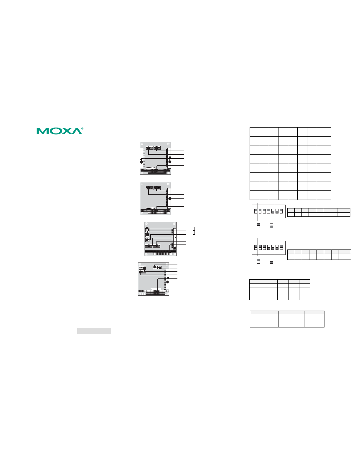
CA-108
SW2: Interrupt Vector
SW1: I/O Base Address
Box Header Connector
PC/104 Slot
CA-104 V2
SW2: Interrupt Vector
SW1: I/O Base Address
Box Header Connector
PC/104 Slot
CA-114
SW3
SW4 Serial Interface
SW5
SW1: I/O Base Address
SW2: Interrupt Vector
PC/104 Slot
Box Header Connector
CA-134I, CA-132 V2, CA-132I V2
RS-422/RS-485
2-WIRE/4-WIRE
SW1: I/O Base Address
SW2: Interrupt Vector
PC/104 Slot
Box Header Connector
20-pin for CA-132 V2, CA-132I V2
40-pin for CA-134I
I/O Base Address
Use DIP switch SW1 to set port 1’s I/O base address. The other ports will
be configured automatically. The default I/O base address is 0×180 and
allows settings from 0×000 to 0×3FF. Some popular settings are provided
below:
A3 A4 A5 A6 A7 A8 A9
8 1 2 4 8 1 2 Hex
ON ON ON ON ON ON ON 0×000
ON ON ON ON ON ON off 0×200
ON ON ON ON ON off off 0×300
ON ON ON ON off off off 0×380
ON ON ON off off off off 0×3C0
ON ON off off off off off 0×3E0
ON off off off off off off 0×3F0
off off off off off off off 0×3F8
off ON ON ON ON ON ON 0×008
off off ON ON ON ON ON 0×018
off off off ON ON ON ON 0×038
off off off off ON ON ON 0×078
off off off off off ON ON 0×0F8
off off off off off off ON 0×2F8
For example, an I/O base address of 0×180
should be set as follows:
A3 A4 A5 A6 A7 A8 A9 Hex
ON ON ON ON off off ON 0×180
ON
DIP
1234567
A3 A4 A5 A6 A7 A8 A9
081
= on, = off
The other serial ports will be set
automatically to 0×188, 0×190, 0×198, etc.
Interrupt Vector
Use DIP switch SW2 to set port 1’s interr upt
vector. The default interrupt vector is 0×1C0,
with SW2 set as follows:
A3 A4 A5 A6 A7 A8 A9 Hex
ON ON ON off off off ON 0×1C0
ON
DIP
1234567
A3 A4 A
5
A6 A
7
A8 A9
01C
= on, = off
Serial Interface
For the CA-114, use S3, S4, and S5 to select the serial interface:
Interface S3 S4 S5 *
RS-232 --- --- ON
RS-422 --- ON off
4-wire RS-485 ON off off
2-wire RS-485 off off off
For the CA-134I, CA-132 V2, and CA-132I V2, use the 2-WIRE/4-WIRE
and RS-422/RS-485 DIP switches to select the serial interface:
Interface 2-WIRE/4-WIRERS422/RS485
RS-422 --- OFF
4-wire RS-485 OFF ON
2-wire RS-485 ON ON
P/N: 1802001043300
Page 2
— 4 — — 5 — — 6 —
4. Hardware Installation
Do not install the drivers until the module has been installed in the
embedded computer. Install the module in the embedded computer as
follows:
STEP 1: Turn the embedded computer off.
STEP 2: On the module, set the I/O base address, interrupt vector, IRQ,
and serial interface (if applicable).
STEP 3: Insert the module into an available PC/104 slot.
STEP 4: Screw the control board in place.
STEP 5: Connect the cables.
STEP 6: Turn the embedded computer on.
5. Software Installation
For detailed software installation instructions, please refer to the CA
Series User’s Manual.
Windows Vista (32-bit)
1. After turning the embedded computer on, log into Windows as
Administrator.
2. Insert the Document and Software CD in the CD-ROM drive.
3. Select Add Hardware from the Control Panel.
4. A window will appear stating that “Windows needs your permission
to continue”. Click Continue.
5. The “Add Hardware Wizard” will open. Click Next to continue.
6. Select Install the hardware that I manually select from a list
(Advanced) and click Next to continue.
7. Select Multi-port serial adapters and click Next to continue.
8. Click Have Disk. For 32-bit (x86) platforms, select the \CA
Series\Software\Windows Vista\x86 folder on the CD and click
OK to continue.
9. Select your CA Series model and click Next to continue.
10. If you see a warning that the software has not passed Windows
Logo testing, click Install this driver software anyway.
11. The installation wizard will guide you through the port installation
procedure, starting with port 0.
12. If the default configuration is not used, you will need to change the
driver settings to match the hardware configuration. Use Windows
Device Manager to check and set the correct resource.
Windows 2003 and XP (32-bit)
1. After turning the embedded computer on, log into Windows as
Administrator.
2. Insert the Document and Software CD in the CD-ROM drive.
3. Select Add/Remove Hardware from Control Panel.
4. Select Yes, I have already connected the hardware.
5. Select
Add new hardware device.
6. Select Install the hardware that I manually select from a list
(Advanced).
7. Select Multi-port serial adapters.
8. Select Have Disk. Select the \CA Series\Software\ Windows
XP_2003\x86 folder on the CD.
9. If you see a warning that the software has not passed Windows
Logo testing, click Continue Anyway.
10. Click Finish to complete the driver installation.
11. If the default configuration is not used, you will need to change the
driver settings to match the hardware configuration. Use Windows
Device Manager to check and set the correct resource.
Windows 2000
1. After powering on your PC, log into Windows 2000 as
Administrator.
2. Insert the Document and Software CD in the CD-ROM drive.
3. Select Add/Remove Hardware from Control Panel.
4. Select Add/Troubleshoot a device.
5. Select Add new device.
6. Select No, I want to select the hardware from a list.
7. Select Multi-port serial adapters.
8. Select Have Disk. Select the \CA Series\Software\Windows 2K
folder on the CD and click Next to continue.
9. If you see a warning that the software has not passed Windows
Logo testing, click Yes to proceed with the installation.
10. Click Finish to complete the driver installation.
11. If the default configuration is not used, you will need to change the
driver settings to match the hardware configuration. Use Windows
Device Manager to check and set the correct resource.
Linux
Please refer to the user’s manual for instructions on installing the Linux
drivers.
6. Pin Assignments and Cable Wiring
The box header connector on the module can be used with optional serial
cables to connect to your serial devices. The pin assignments are as
follows:
RS-232 (CA-108*, CA-114, CA-104 V2)
Pin Signal Pin Signal Pin Signal Pin Signal
1 DCD0 11 DCD1 21 DCD2 31 DCD3
2 DSR0 12 DSR1 22 DSR2 32 DSR3
3 RxD0 13 RxD1 23 RxD2 33 RxD3
4 RTS0 14 RTS1 24 RTS2 34 RTS3
5 TxD0 15 TxD1 25 TxD2 35 TxD3
6 CTS0 16 CTS1 26 CTS2 36 CTS3
7 DTR0 17 DTR1 27 DTR2 37 DTR3
9 GND0 19 GND1 29 GND2 39 GND3
* There are two 40-pin box header connectors on the CA-108, each of
which connects to 4 serial ports.
RS-422, 4-wire RS-485 (CA-132 V2, CA-132I V2, CA-114, CA-134I)
Pin Signal Pin Signal Pin* Signal* Pin* Signal*
1 TxD0-(A) 11 TxD1-(A) 21 TxD2-(A) 31 TxD3-(A)
3 TxD0+(B) 13 TxD1+(B) 23 TxD2+(B) 33 TxD3+(B)
5 RxD0+(B) 15 RxD1+(B) 25 RxD2+(B) 35 RxD3+(B)
7 RxD0-(A) 17 RxD1-(A) 27 RxD2-(A) 37 RxD3-(A)
9 GND0 19 GND1 29 GND2 39 GND3
* Pins 21 to 40 are for CA-114, CA-134I only
2- wire RS-485 (CA-132 V2, CA-132I V2, CA-114, CA-134I)
Pin Signal Pin Signal Pin* Signal* Pin* Signal*
5 Data0+(B) 15 Data1+(B) 25 Data2+(B) 35 Data3+(B)
7 Data0-(A) 17 Data1-(A) 27 Data2-(A) 37 Data3-(A)
9 GND0 19 GND1 29 GND2 39 GND3
* Pins 21 to 40 are for CA-114, CA-134I only
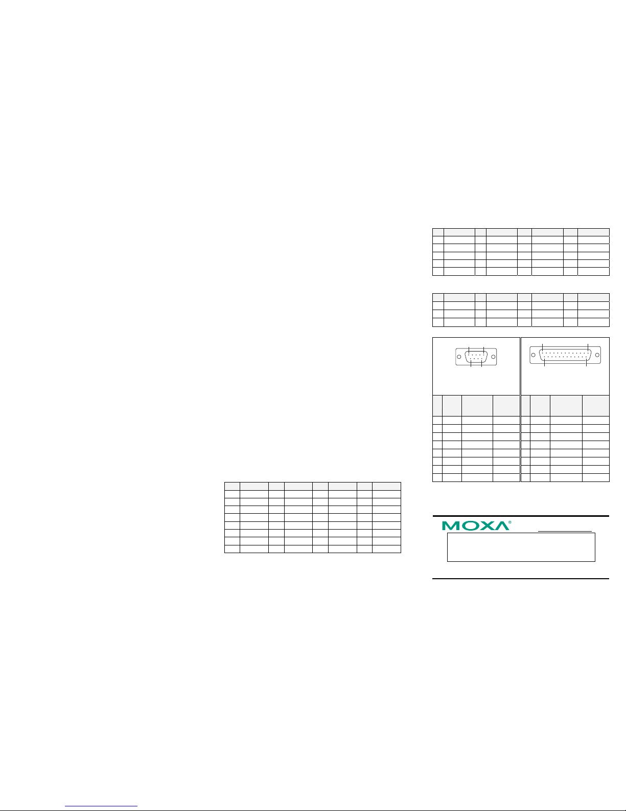
15
69
1
14
13
25
DB9 (M) connectors
(CBL-F40M9x4-50,
CBL-F20M9x4-50)
DB25 (M) connectors
(CBL-F40M25x4-50,
CBL-F20M25x4-50)
PinRS-232
RS-422,
4-wire
RS-485
2-wire
RS-485
Pin RS-232
RS-422,
4-wire
RS-485
2-wire
RS-485
1 DCD TxD-(A) --- 2 TxD RxD+(B) Data+(B)
2 RxD TxD+(B) --- 3 RxD TxD+(B) --3 TxD RxD+(B) Data+(B) 4 RTS --- --4 DTR RxD-(A) Data-(A) 5 CTS --- --5 GND GND GND 6 DSR --- --6 DSR 7 GND GND GND
7 RTS 8 DCD TxD-(A) --8 CTS 20 DTR RxD-(A) Data-(A)
Click here for online support:
www.moxa.com/support
The Americas: +1-714-528-6777 (toll-free: 1-888-669-2872)
Europe: +49-89-3 70 03 99-0
Asia-Pacific: +886-2-8919-1230
China: +86-21-5258-9955 (toll-free: 800-820-5036)
© 2008 Moxa Inc., all rights reserved.
Reproduction without permission is prohibited.
 Loading...