

Moxa Technologies AWK-3131A-M12-RTG, AWK-3131A-SSC-RTG, AWK-3131A-RTG Quick Installation Manual

P/N: 1802031312011
*1802031312011*
AWK-3131A-RTG Series
Quick Installation Guide
Industrial IEEE 802.11n wireless AP/client
Edition 2.0, January 2019
Technical Support Contact Information
www.moxa.com/support
Moxa Americas:
Toll
-free: 1-888-669-2872
Tel:
1-714-528-6777
Fax:
1-714-528-6778
Moxa China (Shanghai office):
Toll
-free: 800-820-5036
Tel:
+86-21-5258-9955
Fax:
+86-21-5258-5505
Moxa Europe:
Tel:
+49-89-3 70 03 99-0
Fax:
+49-89-3 70 03 99-99
Moxa Asia-Pacific:
Tel:
+886-2-8919-1230
Fax:
+886-2-8919-1231
Moxa India:
Tel:
+91-80-4172-9088
Fax:
+91-80-4132-1045
2019 Moxa Inc. All rights reserved.

- 2 -
Overview
The AWK-3131A-RTG Series 3-in-1 industrial AP/client devices are
designed specifically for train-to-ground communication for trains moving
at speeds of up to 120 km/h. The AWK-3131A-RTG is compliant with
mandatory sections of the EN 50155 standard, covering operating
temperature, power input voltage, surge, ESD, and vibration, as well as
conformal coating and power insulation, making the AWK-3131A-RTG
suitable for a variety of industrial applications. Installation is easy, with
DIN-rail mounting that makes it convenient to install the AP inside
distribution boxes, and the wide operating temperature range and IP30
housing with LED indicators, make the AWK-3131A-RTG a convenient yet
reliable solution for any rolling stock application.
Package Checklist
Before installing the AWK-3131A-RTG, verify that the package contains
the following items:
• AWK-3131A-RTG wireless AP/client
• DIN-rail kit
• 2 plastic RJ45 protective cap: One for the console port and the other
for use as a backup
• 1 plastic protective cap for fiber port (AWK-3131A-SSC-RTG only)
• Cable holder with one screw
• Quick installation guide (printed)
• Warranty card
If any of these items is missing or damaged, please contact your
customer service representative for assistance.
NOTE
Antennas are not included with the product and should be
purchased separately. The AWK is certified
for 2 dBi
omni-directional antennas with QMA to RP-SMA adapters.
Installation and Configuration
Before installing the AWK-3131A-RTG, make sure that all items in the
Package Checklist are in the box. In addition, you will need access to a
notebook computer or PC equipped with an Ethernet port. The
AWK-3131A-RTG has a default IP address that you must use when
connecting to the device for the first time.
Step 1: Select the power source
The AWK-3131A-RTG can be powered by a DC power input or PoE (Power
over Ethernet). The AWK-3131A-RTG will use whichever power source
you choose.
Step 2: Connect the AWK to a notebook or PC
Since the AWK-3131A-RTG supports MDI/MDI-X auto-sensing, you can
use either a straight-through cable or crossover cable to connect the
AWK-3131A-RTG to a computer. If the LED indicator on the
AWK-3131A-RTG’s LAN port lights up, it means a connection has been
established.
- 3 -
Step 3: Set up the computer’s IP address
Update the computer’s IP address so that the computer is on the same
subnet as the AWK-3131A-RTG. Since the AWK-3131A-RTG’s default IP
address is 192.168.127.253, and the subnet mask is 255.255.255.0, you
should set the IP address of the computer to 192.168.127.xxx and subnet
mask to 255.255.255.0.
Step 4: Use the web-based manager to configure the AWK
Open your computer’s web browser and type http://192.168.127.253
in the address field to access the homepage of the web-based manager.
Before the homepage opens, you will need to enter the user name and
password. For first-time configuration, enter the default user name and
password given below and then click on the Login button:
User name: admin
Password: root
ATTENTION
For security reasons, we strongly recommend changing the
default
password. To do so, select Maintenance Password
,
and then follow the on-screen instructions.
Step 5: Select the AWK’s operation mode
By default, the AWK-3131A-RTG’s operation mode is set to AP. You can
change the setting in Wireless Settings Basic Wireless Settings if
you would like to use the Client mode.
NOTE
To make the change effective, click Save Configuration
or
Restart; either option saves all changes.

- 4 -
Panel Layout of the AWK-3131A-M12-RTG
1. Grounding screw (M5)
2.
Terminal block for PWR1, PWR2,
relay, DI0, and DI1
3. Reset button
4. System LEDs: PWR1, PWR2,
PoE, FAULT, and STATE LEDs
5. LEDs for signal strength
6. LEDs: CLIENT, WLAN, and LAN
7. RS-232 console port
8. 10/100BaseT(X) M12 port
9. Antenna port A
10.
Antenna port B
11.
Model name
12.
Screw hole for wall-
mounting kit
13.
DIN-rail mounting kit
- 5 -
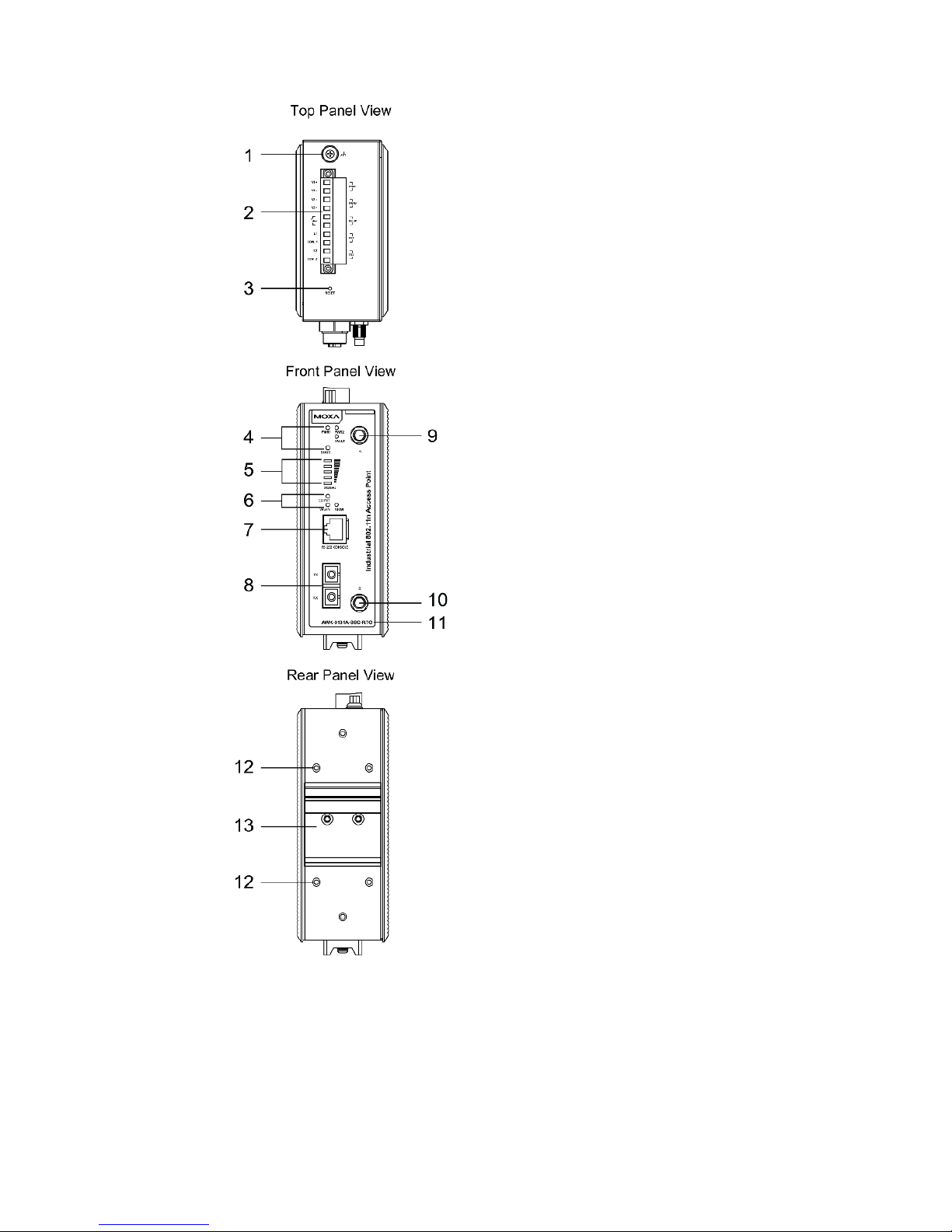
Panel Layout of the AWK-3131A-SSC-RTG
1. Grounding screw (M5)
2.
Terminal block for PWR1, PWR2,
relay, DI0, and DI1
3. Reset button
4. System LEDs: PWR1, PWR2,
FAULT, and STATE LEDs
5. LEDs for signal strength
6. LEDs: CLIENT, WLAN, and
100M
7. RS-232 console port
8. 100BaseFX fiber port
9. Antenna port A
10.
Antenna port B
11.
Model name
12. Screw hole for wall mounting kit
13.
DIN-rail mounting kit
 Loading...