

Moxa Technologies AWK-3131A-M12-RTG, AWK-3131A-SSC-RTG, AWK-3131A-RTG Quick Installation Manual
Page 1

P/N: 1802031312011
*1802031312011*
AWK-3131A-RTG Series
Quick Installation Guide
Industrial IEEE 802.11n wireless AP/client
Edition 2.0, January 2019
Technical Support Contact Information
www.moxa.com/support
Moxa Americas:
Toll
-free: 1-888-669-2872
Tel:
1-714-528-6777
Fax:
1-714-528-6778
Moxa China (Shanghai office):
Toll
-free: 800-820-5036
Tel:
+86-21-5258-9955
Fax:
+86-21-5258-5505
Moxa Europe:
Tel:
+49-89-3 70 03 99-0
Fax:
+49-89-3 70 03 99-99
Moxa Asia-Pacific:
Tel:
+886-2-8919-1230
Fax:
+886-2-8919-1231
Moxa India:
Tel:
+91-80-4172-9088
Fax:
+91-80-4132-1045
2019 Moxa Inc. All rights reserved.
Page 2

- 2 -
Overview
The AWK-3131A-RTG Series 3-in-1 industrial AP/client devices are
designed specifically for train-to-ground communication for trains moving
at speeds of up to 120 km/h. The AWK-3131A-RTG is compliant with
mandatory sections of the EN 50155 standard, covering operating
temperature, power input voltage, surge, ESD, and vibration, as well as
conformal coating and power insulation, making the AWK-3131A-RTG
suitable for a variety of industrial applications. Installation is easy, with
DIN-rail mounting that makes it convenient to install the AP inside
distribution boxes, and the wide operating temperature range and IP30
housing with LED indicators, make the AWK-3131A-RTG a convenient yet
reliable solution for any rolling stock application.
Package Checklist
Before installing the AWK-3131A-RTG, verify that the package contains
the following items:
• AWK-3131A-RTG wireless AP/client
• DIN-rail kit
• 2 plastic RJ45 protective cap: One for the console port and the other
for use as a backup
• 1 plastic protective cap for fiber port (AWK-3131A-SSC-RTG only)
• Cable holder with one screw
• Quick installation guide (printed)
• Warranty card
If any of these items is missing or damaged, please contact your
customer service representative for assistance.
NOTE
Antennas are not included with the product and should be
purchased separately. The AWK is certified
for 2 dBi
omni-directional antennas with QMA to RP-SMA adapters.
Installation and Configuration
Before installing the AWK-3131A-RTG, make sure that all items in the
Package Checklist are in the box. In addition, you will need access to a
notebook computer or PC equipped with an Ethernet port. The
AWK-3131A-RTG has a default IP address that you must use when
connecting to the device for the first time.
Step 1: Select the power source
The AWK-3131A-RTG can be powered by a DC power input or PoE (Power
over Ethernet). The AWK-3131A-RTG will use whichever power source
you choose.
Step 2: Connect the AWK to a notebook or PC
Since the AWK-3131A-RTG supports MDI/MDI-X auto-sensing, you can
use either a straight-through cable or crossover cable to connect the
AWK-3131A-RTG to a computer. If the LED indicator on the
AWK-3131A-RTG’s LAN port lights up, it means a connection has been
established.
Page 3
- 3 -
Step 3: Set up the computer’s IP address
Update the computer’s IP address so that the computer is on the same
subnet as the AWK-3131A-RTG. Since the AWK-3131A-RTG’s default IP
address is 192.168.127.253, and the subnet mask is 255.255.255.0, you
should set the IP address of the computer to 192.168.127.xxx and subnet
mask to 255.255.255.0.
Step 4: Use the web-based manager to configure the AWK
Open your computer’s web browser and type http://192.168.127.253
in the address field to access the homepage of the web-based manager.
Before the homepage opens, you will need to enter the user name and
password. For first-time configuration, enter the default user name and
password given below and then click on the Login button:
User name: admin
Password: root
ATTENTION
For security reasons, we strongly recommend changing the
default
password. To do so, select Maintenance Password
,
and then follow the on-screen instructions.
Step 5: Select the AWK’s operation mode
By default, the AWK-3131A-RTG’s operation mode is set to AP. You can
change the setting in Wireless Settings Basic Wireless Settings if
you would like to use the Client mode.
NOTE
To make the change effective, click Save Configuration
or
Restart; either option saves all changes.
Page 4

- 4 -
Panel Layout of the AWK-3131A-M12-RTG
1. Grounding screw (M5)
2.
Terminal block for PWR1, PWR2,
relay, DI0, and DI1
3. Reset button
4. System LEDs: PWR1, PWR2,
PoE, FAULT, and STATE LEDs
5. LEDs for signal strength
6. LEDs: CLIENT, WLAN, and LAN
7. RS-232 console port
8. 10/100BaseT(X) M12 port
9. Antenna port A
10.
Antenna port B
11.
Model name
12.
Screw hole for wall-
mounting kit
13.
DIN-rail mounting kit
Page 5
- 5 -
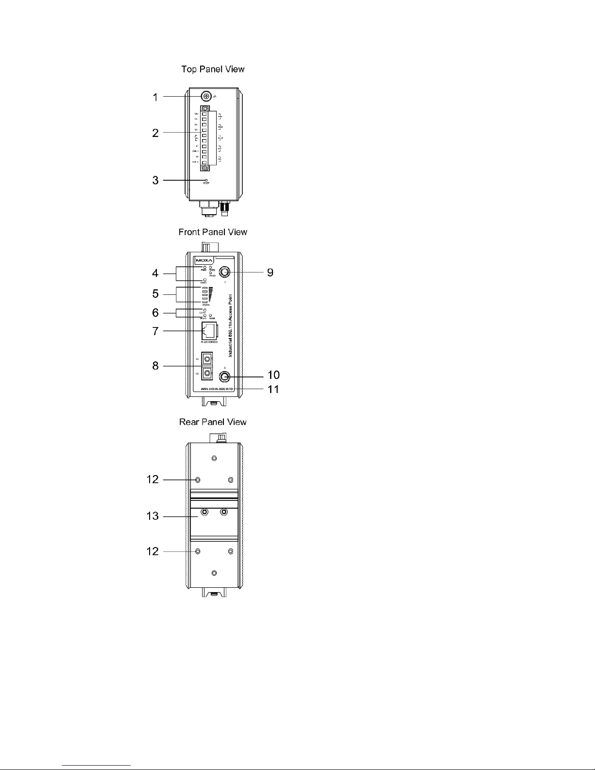
Panel Layout of the AWK-3131A-SSC-RTG
1. Grounding screw (M5)
2.
Terminal block for PWR1, PWR2,
relay, DI0, and DI1
3. Reset button
4. System LEDs: PWR1, PWR2,
FAULT, and STATE LEDs
5. LEDs for signal strength
6. LEDs: CLIENT, WLAN, and
100M
7. RS-232 console port
8. 100BaseFX fiber port
9. Antenna port A
10.
Antenna port B
11.
Model name
12. Screw hole for wall mounting kit
13.
DIN-rail mounting kit
Page 6

- 6 -
Mounting Dimensions (unit = mm)
AWK-3131A-M12-RTG
AWK-3131A-SSC-RTG
DIN-rail Mounting
The aluminum DIN-rail attachment plate should be fixed to the back panel
of the AWK-3131A-RTG when you take it out of the box. If you need to
reattach the DIN-rail attachment plate to the AWK-3131A-RTG, make
sure the stiff metal spring is situated towards the top, as shown in the
figures below:
Page 7

- 7 -
STEP 1:
Insert the top of
the DIN rail into the
slot just below the stiff metal spring.
STEP 2:
The DIN
-rail attachment unit will
snap into place as shown below.
To remove the AWK-3131A-RTG from the DIN rail, simply reverse the
steps 1 and 2.
Wall Mounting (Optional)
For some applications, it may be more convenient to mount the
AWK-3131A-RTG to a wall, as illustrated below.
STEP 1:
Remove the aluminum
DIN
-rail attachment plate
from the AWK
-3131A-RTG,
and then attach the wall
mount
plates with M5
screws, as shown in the
diagrams.
STEP 2:
Mounting the AWK
-3131A-RTG to a wall requires 4
screws. Use the AWK
-3131A-
RTG with wall mount plates
attached as a guide to mark the correct locations of the 4
screws. The heads of the screws should be less than 6.0
mm in diameter, and the shafts should be less than 3.5
mm in diameter, as shown in the figure at the right.
Do not screw the screws in all the way—leave a space of about 2 mm to
allow room for sliding the wall mount panel between the wall and the
screws.
NOTE
Test the screw head and shank size by inserting the screw into
one of the keyhole shaped apertures of the Wall Mounting Plates
before it is screwed into the wall.
Page 8

- 8 -
STEP 3:
Once the screws are fixed into
the wall, insert the
four screw
heads through the large opening
of the keyhole
-shaped
apertures, and then slide the
AWK
-3131A-RTG downwards,
as indicated to the right. Tighten
the four screws for added
stability.
WARNING
•
This equipment is intended to be used in a
Restricted Access
Location, such as a dedicated computer room, with access
restricted to SERVICE PERSONNEL
or USERS who have been
instructed about the fact that the metal chassis of the
equipment is extremely hot and may cause burns.
•
Service personnel or users need
to pay special attention and
take special precautions before handling the equipment.
• Access is to be controlled through the use of a lock and key or
a security identity system, controlled by the authority
responsible for the location. Only authorized, well-trained
professionals should be allowed to access the restricted
access location.
•
External metal parts are hot!! Pay special attention or use
special protection before handling.
Wiring Requirements
WARNING
Safety First!
Be sure to disconnect the power cord before installing and/or
wiring your Moxa AWK-3131A-RTG.
WARNING
Safety First!
Calculate the maximum possible current in each power wire and
common wire. Observe all
electrical codes dictating the
maximum current allowed for each wire size.
If the curren
t goes
above the maximum rating
, the wiring could overheat, causing
serious damage to your equipment.
Page 9

- 9 -
You should also pay attention to the following items:
• Use separate paths to route wiring for power and devices. If power
wiring and device wiring paths must cross, make sure the wires are
perpendicular at the intersection point.
NOTE: Do not run signal or communications wiring and power wiring
in the same wire conduit. To avoid interference, wires with different
signal characteristics should be routed separately.
• You can use the type of signal transmitted through a wire to
determine which wires should be kept separate. The rule of thumb is
that wiring with similar electrical characteristics can be bundled
together.
• Keep input wiring and output wiring separate.
• It is strongly advised that you label wiring to all devices in the system
when necessary.
ATTENTION
This product is intended
to be supplied by a Listed Power Unit
marked
“Class 2” or “LPS” and rated O/P:
•
AWK-3131A-M12-RTG:
Maximum 10.5 W (12 V/0.85 A to 48 V/0.22 A), 25°C.
•
AWK-3131A-SSC-RTG:
Maximum 13 W (12 V/1.0 A to 48 V/0.27 A), 25°C.
ATTENTION
Make sure
the external power adapte
r (includes power cords and
plug assemblies) provided with the unit is certified and suitable
for use in your country.
Grounding the Moxa AWK-3131A-RTG
Grounding and wire routing help limit the effects of noise due to
electromagnetic interference (EMI). Run the ground connection from the
ground screw to the grounding surface prior to connecting devices.
ATTENTION
This product is intended to be mounted to a well
-grounded
mounting surface, such as a metal panel.
Installations with Unstable Power Inputs
There are cases where the device has to be wired to the same power
source as other equipment. In such cases if equipment such as motors
that are connected in the circuit draw a large amount of current during
operation, the transient voltage drop could potentially cause the AWK to
become unstable.
Page 10

- 10 -
Installing a DC/DC power isolator, in between the two equipment, is
recommended to isolate the transient effect and to ensure a stable power
input for the AWK.
Wiring the Redundant Power Inputs
The top two pairs of contacts of the 10-contact terminal block connector
on the AWK-3131A-RTG’s top panel are used for the AWK-3131A-RTG’s
two DC inputs. Top and front views of the terminal block connector are
shown here.
STEP 1:
Insert the negative/positive DC wires into the
V
-/V+ terminals.
STEP 2:
To keep the DC wires from pulling
loose, use a
small flat
-blade screwdriver to tighten the
wire
-clamp screws on the front of the terminal
block connector.
STEP 3:
Insert the plastic terminal block connector prongs
into the terminal block receptor, which is
located
on the AWK-3131A-RTG’s top panel.
ATTENTION
Before connecting the
AWK-3131A-RTG
to the DC power inputs,
make sure the DC power source voltage is stable.
Wiring the Relay Contact
The AWK-3131A-RTG has one relay output, which consists of the two
contacts of the terminal block on the AWK-3131A-RTG’s top panel. Refer
to the previous section for detailed instructions on how to connect the
wires to the terminal block connector, and how to attach the terminal
block connector to the terminal block receptor. These relay contacts are
used to indicate user-configured events. The two wires attached to the
Relay contacts form an open circuit when a user-configured event is
triggered. If a user-configured event does not occur, the relay circuit will
be closed.
Page 11

- 11 -
Wiring the Digital Inputs
The AWK-3131A-RTG has two sets of digital inputs: DI0 and DI1. Each DI
comprises two contacts of the 10-pin terminal block connector on the
AWK-3131A-RTG’s top panel. Refer to the “Wiring the Redundant Power
Inputs” section for detailed instructions on how to connect the wires to
the terminal block connector, and how to attach the terminal block
connector to the terminal block receptor.
Cable Holder Installation (Optional)
You can attach the cable holder to the bottom of the AWK-3131A-RTG to
keep cabling neat and avoid accidents that result from untidy cables.
STEP 1:
Screw the cable holder onto the bottom of the
AWK
-3131A-RTG.
STEP 2:
After mounting the AWK
-3131A-RTG and plugging in the LAN cable,
tighten the cable along the device and wall.
Communication Connections
100BaseFX Fiber Port Connection
The concept behind the SC port and cable is quite straightforward.
Suppose you are connecting devices 1 and 2; contrary to electrical signals,
optical signals do not need a circuit in order to transmit data.
Consequently, one of the optical lines is used to transmit data from device
1 to device 2, and the other optical line is used to transmit data from
device 2 to device 1, for full-duplex transmission. Remember to connect
the Tx (transmit) port of device 1 to the Rx (receive) port of device 2, and
vice versa.
Page 12

- 12 -
If you make your own cable, we suggest labeling the two sides of the
same line with the same letter (A-to-A and B-B, as illustrated below, or
(A1-to-A1, B1-to-B2, etc.).
SC-Port Pinouts
SC-Port to SC-Port Cable Wiring
ATTENTION
This is a Class 1 Laser/LED product. To avoid causing serious
damage to your eyes, do not stare directly into the laser beam.
10/100BaseT(X) Ethernet Port Connection
All AWK-3131A-M12-RTG have a 10/100BaseT(X) Ethernet port (4-pin
shielded M12 connector with D coding). The 10/100TX port located on the
AWK-3131A-M12-RTG’s front panel is used to connect to
Ethernet-enabled devices. Most users configure this port for Auto
MDI/MDI-X mode, in which case the port’s pinouts are adjusted
automatically depending on the type of Ethernet cable used
(straight-through or cross-over), and the type of device (NIC-type or
HUB/Switch-type) connected to the port.
Pinouts for the 10/100BaseT(X) Port
RS-232 Connection
The AWK-3131A-RTG has one RS-232 (8-pin RJ45) console port located
on the front panel. Use either an RJ45-to-DB9 or RJ45-to-DB25 cable to
connect the AWK-3131A-RTG’s console port to your PC’s COM port. You
may then use a console terminal program to access the AWK-3131A-RTG
for console configuration.
Page 13

- 13 -
Console Pinouts for 10-pin or 8-pin RJ45
10-Pin
Connector
Description
8-Pin
Connector
1 – – 2 DSR
1 3 RTS
2 4 GND
3 5 TxD
4 6 RxD
5 7 DCD
6 8 CTS
7 9 DTR
8
10 – –
ATTENTION
For railway rolling stock applications,
the AWK-3131A-
RTG must
use a galvanically isolated power supply that is compliant with the
EN 50155 standard.
LED Indicators
The front panel of the Moxa AWK-3131A-RTG contains several LED
indicators. The function of each LED is described in the table below.
LED
Color
State
Description
PWR1 Green
On
Power is being supplied from power
input 1.
Off
Power is not being supplied from
power input 1.
PWR2 Green
On
Power is being supplied from power
input 2.
Off
Power is
not
being supplied from
power input 2.
PoE
(AWK-3131
A-M12-RTG
only)
Amber
On
Power is being supplied via PoE.
Off
Power is not being supplied via PoE.
FAULT Red
Blinking
(slow at
1-second
intervals)
Cannot get an IP address from the
DHCP server
Blinking
(fast at
0.5-second
intervals)
IP address conflict
Off
No errors
STATE
Green/
Red
Green
System startup is complete and the
system is in operation
Green
(blinking at
1-second
intervals)
The AWK has been located by the
Wireless Search Utility.
Red
Boot up error
Page 14

- 14 -
LED
Color
State
Description
SIGNAL
(5 LEDs)
Green
On
Signal level
(for Client and Client-Router
mode only)
Off
CLIENT
MODE
Green
On
The AWK is functioning in Client or
Client-Router Mode.
Off
The AWK is not functioning in Client
or Client-Router Mode.
WLAN Amber
On
WLAN is in use.
Off
WLAN is not in use.
LAN/
100M*
Green
On
100 Mbps link is active.
Blinking
Data is being transmitted at 100
Mbps.
Off
100 Mbps link is inactive.
*100M applies to the AWK-3131A-SSC-RTG model only.
Specifications
Input Current
0.6 A @ 12 VDC; 0.15 A @ 48 VDC
Input Voltage 12 to 48 VDC, redundant dual DC power
inputs or 48 VDC Power-over-Ethernet Plus
(IEEE 802.3af compliant)
Power Consumption
7.2 W
Operating Temperature
Standard Models: -25 to 60°C (-13 to 140°F)
Wide Temp. Models: -40 to 75°C (-40 to
167°F)
Storage Temperature
-40 to 85°C (-40 to 185°F)
ATTENTION
The AWK
-3131A-SCC-RTG is an industrial wireless device and
hence the antenna should be installed such that it is located at
least 10 cm away from the SC fiber port to ensure proper working
of the fiber port.
The AWK-3131A-RTG is NOT
a portable mobile
device and should be located at least 20 cm away from the human
body.
The AWK
-3131A-RTG is NOT
designed for the general public. To
establish a wireless network safely using the AWK
-3131A-
RTG, a
well-trained technician should be consulted for installation.
ATTENTI
ON
Use the antennas correctly: 2.4 GHz antennas are needed when
the AWK
-3131A-RTG operates in an IEEE 802.11b/g/n wireless
environment
. 5 GHz antennas are needed for an
IEEE 802.11a/n
environment
. Make sure your antenna is installed
in a safe area
that is covered by a lightning protection or surge arrest system.
 Loading...