

Page 1

P/N: 1802011370011
*1802011370011*
AWK-1137C
Quick Installation Guide
Moxa AirWorks
Edition 2.0, August 2017
Technical Support Contact Information
www.moxa.com/support
Moxa Americas:
Toll
-free: 1-888-669-2872
Tel:
1-714-528-6777
Fax:
1-714-528-6778
Moxa China (Shanghai office):
Toll
-free: 800-820-5036
Tel:
+86-21-5258-9955
Fax:
+86-21-5258-5505
Moxa Europe:
Tel:
+49-89-3 70 03 99-0
Fax:
+49-89-3 70 03 99-99
Moxa Asia-Pacific:
Tel:
+886-2-8919-1230
Fax:
+886-2-8919-1231
Moxa India:
Tel:
+91-80-4172-9088
Fax:
+91-80-4132-1045
2017 Moxa Inc. All rights reserved.
Page 2

- 2 -
Overview
The AWK-1137C industrial Wi-Fi client meets the growing need for faster
data transmission speeds and wider coverage by supporting IEEE
802.11n technology with a net data rate of up to 300 Mbps. The
AWK-1137C combines two adjacent 20 MHz channels into a single 40 MHz
channel to deliver a potent combination of greater reliability and more
bandwidth. The AWK-1137C can operate on either the 2.4 or the 5 GHz
band and is backward compatible with existing 802.11a/b/g
deployments.
Hardware Setup
This section covers the hardware setup for the AWK-1137C.
Package Checklist
Moxa’s AWK-1137C is shipped with the following items. If any of these
items is missing or damaged, please contact your customer service
representative for assistance.
• 1 AWK-1137C wireless client
• 2 2.4/5 GHz omni-directional antennas: ANT-WDB-ARM-0202
• DIN-rail kit
• Quick installation guide (printed)
• Warranty card
Page 3
- 3 -
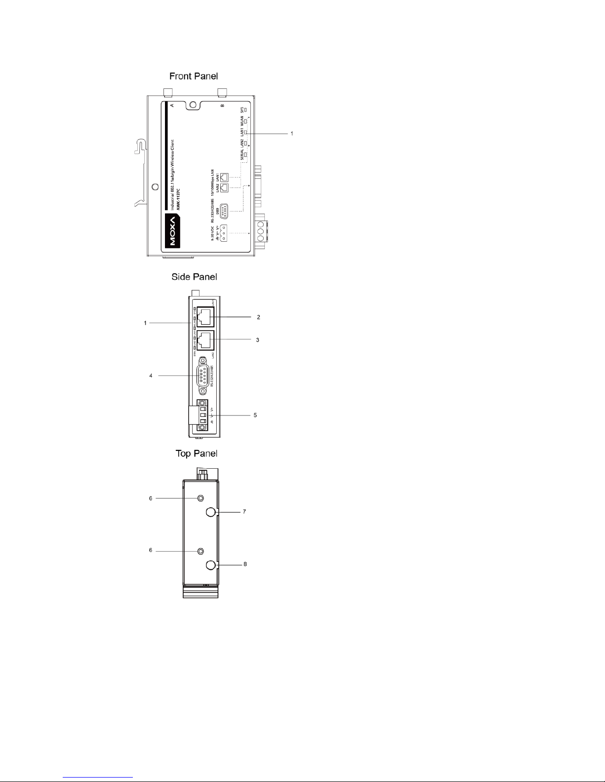
Panel Layout of the AWK-1137C
1. System LEDs: SYS, WLAN,
LAN1, LAN2, and SERIAL
2. LAN1: 10/100 BaseT(X) RJ45
port
3. LAN2: 10/100 BaseT(X) RJ45
port
4. RS-232/422/485 DB9 serial
port
5. 3-pin terminal block
(ground/-/+)
6. M3 screw holes for antenna
bracket
7. Antenna B RP-SMA
8. Antenna A RP-SMA
Page 4
- 4 -
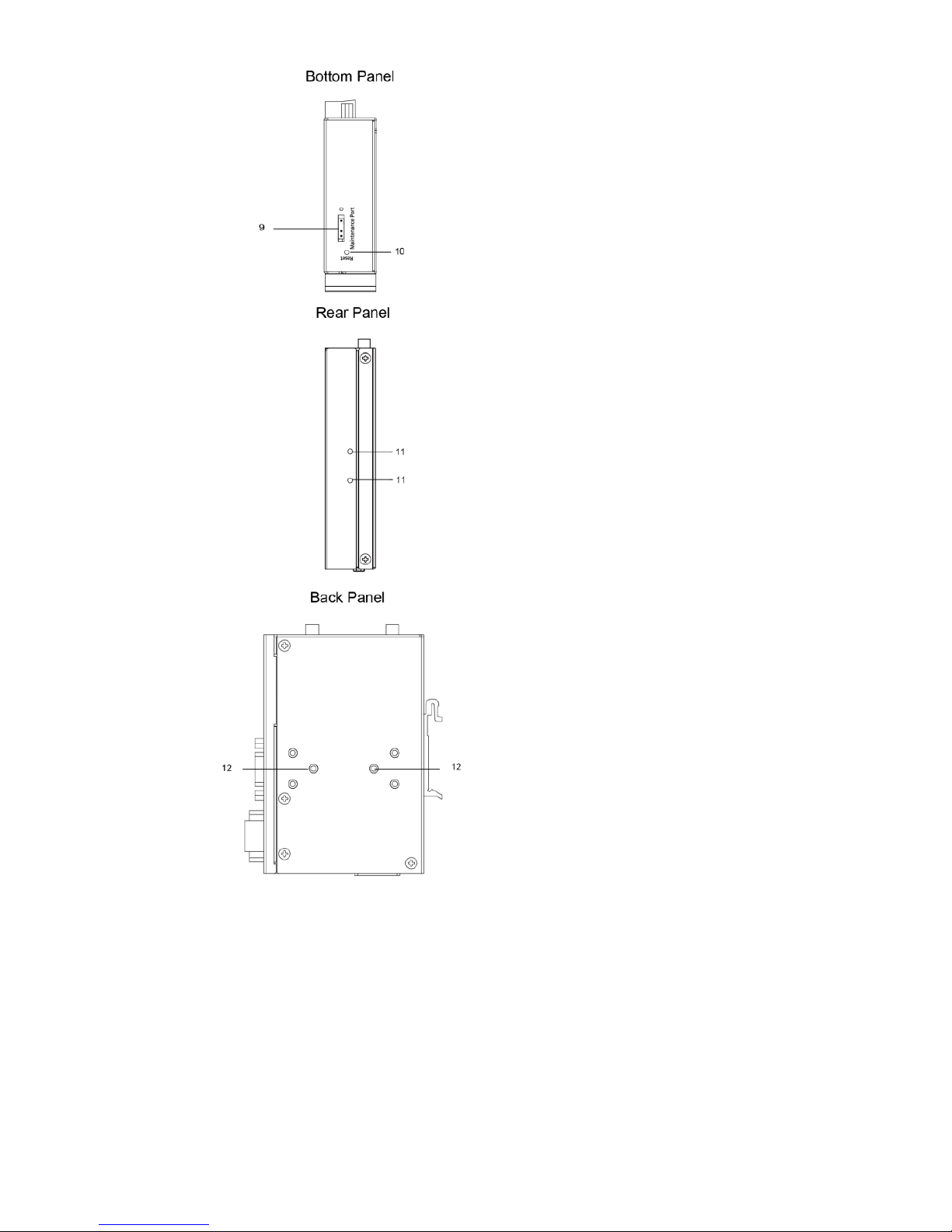
9. 3-pin maintenance port for
engineers
10.
Reset button
11.
Screw holes for DIN-rail
mounting kit
12.
Screw holes for wall-mounting
kit
Page 5
- 5 -
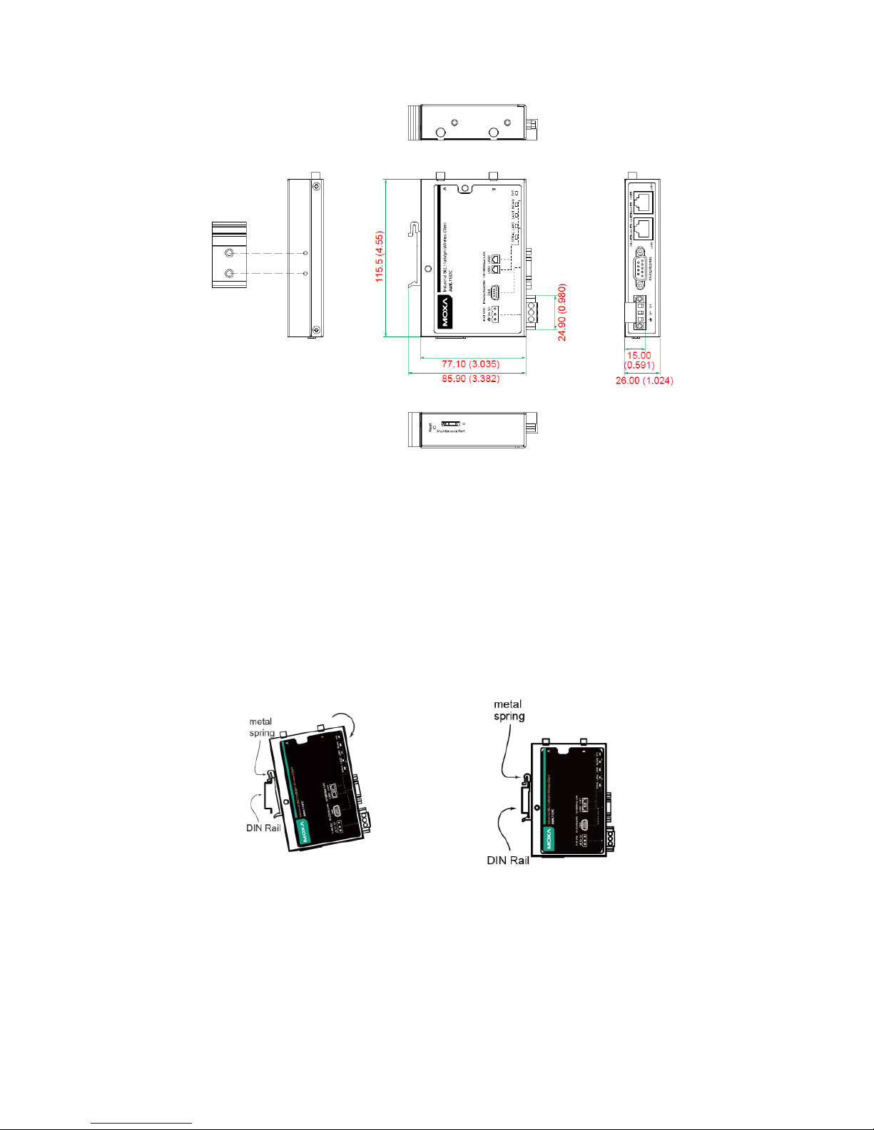
Mounting Dimensions
Unit = mm (inch)
DIN-Rail Mounting
The aluminum DIN-rail attachment plate comes attached to the back
panel of the AWK-1137C when you take it out of the box. If you need to
reattach the DIN-rail attachment plate to the AWK-1137C, make sure the
stiff metal spring is situated towards the top, as shown in the figures
below:
STEP 1:
Insert the top of the DIN rail into
the slot just
below the stiff metal
spring.
STEP 2:
Gently push the device
towards the
DIN rail until the D
IN-
rail attachment
unit snaps into place as shown below:
To remove the AWK-1137C from the DIN rail, reverse steps 1 and 2.
Page 6
- 6 -
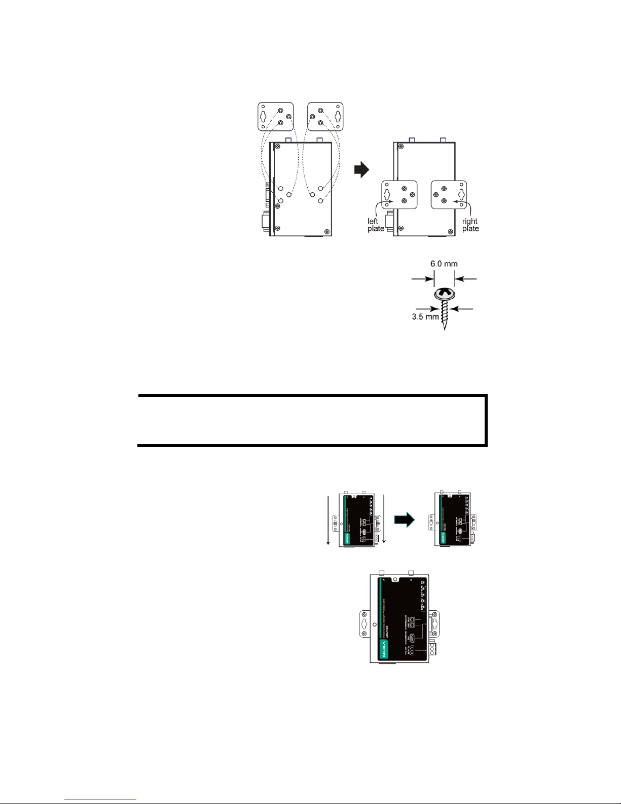
Wall Mounting (Optional)
For some applications, it may be more convenient to mount the
AWK-1137C to a wall, as illustrated below:
STEP 1:
Remove the aluminum
DIN
-rail attachment
plate from the
AWK
-1137C, and then
attach the
wall
-mounting plates
with M3 screws, as
shown in the adjacent
diagrams.
STEP 2:
Mounting the
AWK-1137C to a wall requires two
screws. Use
the AWK-1137C device, with
wall
-mounting
plates attached, as a guide to mark the
correct locations of the
two screws. The heads of the
screws should be less than 6.0 mm in diameter, and
the
shafts should be less than 3.5
mm in diameter, as
shown in the figure on the right.
Do not drive the screws in all the way—leave a space of about 2 mm to
allow room for sliding the wall-mounting panel between the wall and the
screws.
NOTE
Test the screw head and shank size by inserting the screws into
one of the keyhole
-shaped apertures of the wall-
mounting plates
before they are fixed to the wall.
STEP 3a:
Once the screws are fixed into the wall,
insert the
two
screw heads through the
large opening of the keyhole
-shaped
apertures, and then slide the
AWK
-1137C downwards, as indicated
to the right. Tighten the
two
screws for
added stability.
STEP 3b:
Alternatively, insert four screws
directly through the
AWK-1137C into
the wall.
Page 7

- 7 -
WARNING
•
This equipment is intended to be used in a
Restricted Access
Location, such as a dedicated computer room where only
authorized service personnel or users can gain access.
Such
personnel must be instructed about the fact that the metal
chassis of the equipment is extremely hot and may cause
burns.
•
Service personnel
or users have to pay special attention and
take special precautions before handling this equipment.
•
Only authorized, well-trained professionals should be a
llowed
to access the Restricted Access Location. Access should be
controlled by the authority responsible for the location with
a
lock and key or a security identity system.
•
External metal parts are hot!! Pay special attention or
use
special protection before handling this equipment.
Wiring Requirements
WARNING
Safety First!
Be sure to disconnect the power cord before installing and/or
wiring your M
oxa AWK-1137C.
Calculate the maximum possible current in each power wire and
common wire. Observe all electrical codes that dictate the
maximum current allowed for each wire size. If the current goes
above the maximum ratings, the wiring could overheat, causing
serious damage to your equipment.
You should also pay attention to the following items:
• Use separate paths to route wiring for power and devices. If power
wiring and device wiring paths must cross, make sure the wires are
perpendicular at the intersection point.
NOTE
Do not run signal or communications wiring and power wiring in
the same wire conduit. To avoid interference, wires with different
signal characteristics should be routed separately.
• You can use the type of signal transmitted through a wire to
determine which wires should be kept separate. The rule of thumb is
that wiring with similar electrical characteristics can be bundled
together.
• Keep input wiring and output wiring separate.
• It is strongly advised that you label wiring to all devices in the system
when necessary.
Page 8

- 8 -
ATTENTION
This product is intended to be supplied by a UL
-listed power
adapter suitable for
use at a Thermom
echanical Analysis (TMA) of
7
5 degree Celsius, which output meets SELV circuit and LPS
standards;
output rated 9 - 30Vdc, 1.3A min. or 24Vdc, 0.49A
min.
ATTENTION
Make sure
the external power adapte
r (includes power cords and
plug assemblies) provided with the unit is certified and suitable
for use in your country.
Grounding the Moxa AWK-1137C
Grounding and wire routing help limit the effects of noise due to
electromagnetic interference (EMI). Run the ground connection from the
ground screw to the grounding surface prior to connecting devices.
ATTENTION
This product is intended to be mounted to a well
-grounded
mounting surface, such as a metal panel.
There must be no
electrical potential difference between any two grounding points;
otherwise, there is a risk that the device could be destroyed.
Installing Cable Extended Antennas for Outdoor Applications
If the antenna or the AWK device is installed outdoors or in an open-air
setting, proper lightning protection is required to prevent direct lightning
strikes on the AWK device. In order to prevent coupling currents from
nearby lightning strikes, a lightning arrester should be installed as part of
your antenna system. Ground the device, antenna, as well as the arrester
properly to provide maximum outdoor protection for the device.
Page 9

- 9 -
Arrester Accessories
• SA-NMNF-01: Surge arrester, N-type (male) to N-type (female)
• SA-NFNF-01: Surge arrester, N-type (female) to N-type (female)
Wiring the Redundant Power Inputs
The top two pairs of contacts of the 10-contact terminal block connector
on the AWK-1137C’s top panel are used for the AWK-1137C’s two DC
inputs. The top and front views of the terminal block connector are shown
below:
STEP 1:
Insert the negative/positive DC wires into the
V
-/V+ terminals.
STEP 2:
To keep the DC wires from pulling
loose, use a
small flat
-blade screwdriver to tighten the
wire
-clamp screws on the front of the terminal
block
connector.
STEP 3:
Insert the plastic terminal block connector
prongs into the terminal block receptor, which is
located on
the AWK-1137C’s side panel.
NOTE
Input Terminal Block (CN1) is suitable for wire size range of
12
-28 AWG (3.31-0.0804 mm²) and a torque value of 4.5 lb-in
(0.51 Nm)
ATTENTION
If the
AWK-1137C
is connected to a motor or other similar type of
equipment, be sure to use power isolation protection. Before
connecting the
AWK-1137C to the DC power inputs, make sure
the DC power source voltage is stable.
Using the Reset Button
The Reset button is used to load the factory default settings. Use a
pointed object to hold the Reset button down for five seconds to load the
factory defaults.
Activating AeroMag Function
Push the Reset Button five times to activate AeroMag. To deactivate it
again, push the Reset Button three times.
Page 10

- 10 -
Installing the Antenna-Locking Clamp
Use the antenna-locking clamp to secure the antennas to the AWK-1137C
for added stability when you install the device in a high-vibration
environment.
STEP 1:
Slide the clamps
into the antenna
port.
STEP 2:
Use s
crews to fix the clamps to the
side
panel of the AWK-1137C as
shown below:
Communication Connections
10/100BaseT(X) Ethernet Port Connection
The 10/100BaseT(X) ports located on the AWK-1137C’s front panel are
used to connect to Ethernet-enabled devices.
The pinouts for both the MDI (NIC-type) and MDI-X (HUB/switch-type)
ports as shown below:
MDI Port Pinouts
MDI-X Port Pinouts
8-pin RJ45
Pin
Signal
1
Tx+
2
Tx-
3
Rx+
6
Rx-
Pin
Signal
1
Rx+
2
Rx-
3
Tx+
6
Tx-
RS-232/422/485 Serial Port
The AWK-1137C has 1 RS-232/422/485 serial port with DB9 connector
for serial-to-WLAN connectivity. The pin assignments for the serial ports
are shown below:
Pin RS-232
RS-422/485
(4W)
RS-485
(2W)
1
DCD
TxD-(A)
– 2 RxD
TxD+(B)
– 3 TxD
RxD+(B)
Data+(B)
4
DTR
RxD-(A)
Data-(A)
5
GND
GND
GND
6
DSR – – 7 RTS – – 8 CTS – – 9 – – –
Page 11

- 11 -
LED Indicators
The front and side panel of the Moxa AWK-1137C contains several LED
indicators. The function of each LED is described in the table below:
LED
Color
State
Description
SYS
Green
On
System start up complete and the
system is in operation
Blinking +
Beeps
(Interval: 1
second)
Device has been located by the
Wireless Search Utility
Red
On
System is booting or a system booting
error has occurred
Blinking
(Interval: 0.5
second)
IP address conflict
Blinking
(Interval: 1
second)
Cannot obtain an IP address from the
DHCP server
WLAN
Green
On
(RSSI > 35)
WLAN interface has connected
Blinking
Data communication via WLAN
Amber
On
(RSSI < 35)
WLAN interface has connected
Blinking
Data communication via WLAN
LAN1
Green
On
Ethernet LAN 1 interface has
connected
Blinking
Data communication via Ethernet LAN
1
LAN2
Green
On
Ethernet LAN 2 interface has
connected
Blinking
Data communication via Ethernet LAN
2
Serial
Amber
Blinking
Data Transmission via serial data port
Specifications
WLAN Interface
Standards
IEEE 802.11a/b/g/n for Wireless LAN
IEEE 802.11i for Wireless Security
IEEE 802.3 for 10BaseT
IEEE 802.3u for 100BaseT(X)
IEEE 802.1Q VLAN
Spread Spectrum and
Modulation (typical)
• DSSS with DBPSK, DQPSK, CCK
• OFDM with BPSK, QPSK, 16QAM, 64QAM
• 802.11b: CCK @ 11/5.5 Mbps, DQPSK @ 2
Mbps, DBPSK @ 1 Mbps
• 802.11a/g: 64QAM @ 54/48 Mbps,
16QAM @
36/24 Mbps, QPSK @ 18/12 Mbps, BPSK @
9/6 Mbps
• 802.11n: 64QAM @ 300 Mb
ps to BPSK @ 6.5
Mbps (multiple rates supported)
Page 12

- 12 -
WLAN Interface
Operating Channels
(central frequency)
US:
• 2.412 to 2.462 GHz (11 channels)
• 5.180 to 5.240 (4 channels)
• 5.260 to 5.320 (4 channels)
• 5.500 to 5.700 GHz (8 channels, excluding
5.600 to 5.640 GHz)
• 5.745 to 5.825 GHz (5 channels)
EU:
• 2.412 to 2.472 GHz (13 channels)
• 5.180 to 5.240 GHz (4 channels)
• 5.260 to 5.320 GHz (4 channels)
• 5.500 to 5.700 GHz (11 channels)
JP:
• 2.412 to 2.484 GHz (14 channels)
• 5.180 to 5.240 GHz (4 channels)
• 5.260 to 5.320 GHz (4 channels)
• 5.500 to 5.700 GHz (11 channels)
Security
• SSID broadcast enable/disable
• Firewall for MAC/IP/Protocol/Port-based
filtering
• 64-bit and 128-bit WEP encryption
• WPA/WPA2-Personal and Enterprise (IEEE
802.1X/RADIUS, TKIP, and AES)
Transmission Rates
• 802.11b: 1, 2, 5.5, 11 Mbps
• 802.11a/g: 6, 9, 12, 18, 24, 36, 48, 54 Mbps
• 802.11n: 6.5 to 300 Mbps (multiple rates
supported)
Transmitter Power
802.11b:
• Typ. 26±1.5 dBm @ 1 Mbps
• Typ. 26±1.5 dBm @ 2 Mbps
• Typ. 26±1.5 dBm @ 5.5 Mbps
• Typ. 25±1.5 dBm @ 11 Mbps
802.11g:
• Typ. 23±1.5 dBm @ 6 to 24 Mbps
• Typ. 22±1.5 dBm @ 36 Mbps
• Typ. 20±1.5 dBm @ 48 Mbps
• Typ. 19±1.5 dBm @ 54 Mbps
802.11n (2.4 GHz):
• Typ. 23±1.5 dBm @ MCS0/8 20 MHz,
• Typ. 17±1.5 dBm @ MCS7/15 20 MHz
• Typ. 23±1.5 dBm @ MCS0/8 40 MHz,
• Typ. 17±1.5 dBm @ MCS7/15 40 MHz
802.11a:
• Typ. 23±1.5 dBm @ 6 to 24 Mbps
• Typ. 21±1.5 dBm @ 36 Mbps
• Typ. 20±1.5 dBm @ 48 Mbps
• Typ. 18±1.5 dBm @ 54 Mbps
802.11n (5 GHz):
• Typ. 23±1.5 dBm @ MCS0/8 20 MHz,
• Typ. 18±1.5 dBm @ MCS7/15 20 MHz
• Typ. 23±1.5 dBm @ MCS0/8 40 MHz,
• Typ. 18±1.5 dBm @ MCS7/15 40 MHz
Page 13

- 13 -
NOTE
Based on regional regulations, the maximum transmission power
allowed on UNII bands is restricted in the firmware, as indicate
below.
US
EU
JP
2.4 GHz
26 dBm
18 dBm
18 dBm
5 GHz (UNII-1)
23 dBm
23 dBm
23 dBm
5 GHz (UNII-2)
23 dBm
23 dBm
23 dBm
5 GHz (UNII-2e)
23 dBm
23 dBm
23 dBm
5 GHz (UNII-3)
23 dBm
--
--
Receiver Sensitivity
• 802.11b:
-89 dBm @ 1 Mbps, -89 dBm @ 2 Mbps
-89 dBm @ 5.5 Mbps, -88 dBm @ 11 Mbps
• 802.11g:
-88 dBm @ 6 Mbps, -88 dBm @ 9 Mbps
-88 dBm @ 12 Mbps, -87 dBm @ 18 Mbps
-84 dBm @ 24 Mbps, -81 dBm @ 36 Mbps
-77 dBm @ 48 Mbps, -75 dBm @ 54 Mbps
• 802.11n (2.4 GHz):
-70 dBm @ MCS7 20 MHz,
-70 dBm @ MCS15 20 MHz,
-64 dBm @ MCS7 40 MHz,
-65 dBm @ MCS15 40 MHz
• 802.11a:
-90 dBm @ 6 Mbps, -88 dBm @ 9 Mbps
-87 dBm @ 12 Mbps, -85 dBm @ 18 Mbps
-81 dBm @ 24 Mbps, -78 dBm @ 36 Mbps
-74 dBm @ 48 Mbps, -73 dBm @ 54 Mbps
• 802.11n (5 GHz):
-69 dBm @ MCS7 20 MHz,
-70 dBm @ MCS15 20 MHz,
-64 dBm @ MCS7 40 MHz,
-66 dBm @ MCS15 40 MHz
Protocol Support
General Protocols
Proxy ARP, DNS, HTTP, HTTPS, IP, ICMP, SNTP,
TCP, UDP, RADIUS, SNMP, DHCP, VLAN
Interface
Default Antennas 2 dual-band omni-directional antennas, 1.8 dBi,
RP-SMA (male)
Connector for External
Antennas
RP-SMA (female), 500 V insulation
LAN Ports
2, RJ45, 10/100BaseT(X) auto negotiation speed,
F/H duplex mode, and auto MDI/MDI-X
connection
Serial Port
1, RS-232/422/485, DB9 male connector
Reset
Present
LED Indicators
SYS, WLAN, LAN1, LAN2, Serial
Physical Characteristics
Housing
Metal, providing IP30 protection
Weight
470 g (1.03 lb)
Dimensions
77.1 x 115.5 x 26 mm (3.035 x 4.55 x 1.024 in)
Page 14

- 14 -
Installation
DIN-rail mounting (standard),
wall mounting (optional)
Environmental Limits
Operating
Temperature
Standard Models: 0 to 60°C (32 to 140°F)
Wide Temp. Models: -40 to 75°C (-40 to 167°F)
Storage Temperature
-40 to 85°C (-40 to 185°F)
Ambient Relative
Humidity
5% to 95% (non-condensing)
Power Requirements
Input Voltage
9 to 30 VDC
Input Current
1.3A@9VDC, 0.39A@30VDC, 0.49A@24VDC
Connector
3-pin removable terminal block, 500 V insulation
Power Consumption
11.7 W
Reverse Polarity
Protection
Present
Standards and Certifications
Safety
UL 60950-1, EN 60950-1
EMC
EN 61000-6-2/61000-6-4, EN 55032/55024
EMI
CISPR 22, FCC Part 15B Class B
EMS
IEC 61000-4-2 ESD: Contact 8 kV; Air 15 kV
IEC 61000-4-3 RS: 80 MHz to 1 GHz: 10 V/m
IEC 61000-4-4 EFT: Power 2 kV; Signal 1 kV
IEC 61000-4-5 Surge: Power 2 kV; Signal 1 kV
IEC 61000-4-6 CS: 10 V
IEC 61000-4-8
Radio
EN 301 489-1/17, EN 300 328, EN 301 893, MIC,
FCC ID SLE-1137C, WPC, ANATEL, KC, RCM,
SRRC
Note: Check Moxa’s website for the most up-to-date certification status.
Reliability
MTBF
1,125,942 hrs
Warranty
Warranty Period
5 years
Details
See www.moxa.com/support/warranty.aspx
ATTENTION
•
The AWK-1137C is NOT
a portable mobile device and should
be located at least 20 cm away from the human body.
•
The AWK-1137C is NOT designed for the general public. A
well-trained technician is required to deploy AWK-1137Cs
and safely establish a wireless network.
ATTENTION
Use the antennas correctly: The 2.4 GHz antennas are needed
when the
AWK-1137C
operates in IEEE 802.11b/g/n. The 5 GHz
antennas are needed for operation in IEEE802.11a/n. Make sure
that the antennas are installed in a safe area, which is covered by
a lightning protection or surge arrest system.
Page 15

- 15 -
ATTENTION
This device complies with part 15 of the FCC Rules.
The o
peration
of this device
is subject to the following conditions:
1. This device must not cause harmful interference.
2.
This device must accept any interference received, including
interference that may cause undesired operations.
ATTENTION
Do not locate the antenna near overhead power lines or other
electric light or power circuits, or where it can come into contact
with such circuits. When installing the antenna, take extreme
care not to come into contact with such circuits, becau
se they
may cause serious injury or death. For proper installation and
grounding of the antenna, refer to national and local co
des (for
example, U.S.: NFPA 70;
National Electrical Code (NEC) Article
810; Canada: Canadian Electrical Code, Section 54).
NOTE
For installation flexibility,
you may select either antenna A or
antenna
B on the top panel. Make sure the antenna connection
matches the antenna
s configured in the AWK-1137C web
interface.
To protect the connectors and RF module, all radio ports should
be terminated by either an antenna or a terminator. We strongly
recommend using resistive terminators for terminating the
unused antenna ports.
Federal Communications Commission Interference
Statement
This equipment has been tested and found to comply with the limits for a
Class B digital device, pursuant to part 15 of the FCC Rules. These limits
are designed to provide reasonable protection against harmful
interference in a residential installation. This equipment generates, uses,
and can radiate radio frequency energy and, if not installed and used in
accordance with the instructions, may cause harmful interference to radio
communications. However, there is no guarantee that interference will
not occur in a particular installation. If this equipment does cause harmful
interference to radio or television reception, which can be determined by
turning the equipment off and on, the user is encouraged to try to correct
the interference by one or more of the following measures:
- Reorient or relocate the receiving antenna.
- Increase the separation between the equipment and receiver.
- Connect the equipment into an outlet on a circuit different from that to
which the receiver is connected.
- Consult the dealer or an experienced radio/ TV technician for help.
Page 16

- 16 -
ATTENTION
CAUTION: Any changes or modifications not expressly approved
by the grantee of this device could void the user's authority to
operate the equipment Type message content here.
WARNING
RF exposure:
This equipment must be installed and operated in accordance
with provided instructions and the antenna(s) used for this
transmitter must be installed to provide a separation distance of
at least 20 cm from all persons and must not
be co-located
or operating in conjunction with any other antenna or
transmitter. End
-users and installers must be provided with
antenna installation instructions and transmitter
operating conditions for satisfying RF exposure compliance.
This radio transmi
tter FCCID: SLE-1137C has been appr
oved by
FCC to operate with the
antenna types listed below with the
maximum permissible gain and required antenna impedance for
each antenna type indicated. Antenna types not included in this
list,
having a gain greater t
han the maximum gain indicated for
that type, are strictly prohibited for use with this device.
Software Setup
This section covers the software setup for AWK models in general.
How to Access the AWK
Before installing the AWK device (AWK), make sure that all items in the
package checklist are provided in the product box. You will also need
access to a notebook computer or PC equipped with an Ethernet port.
• Step 1: Select a suitable power source and plug in the AWK.
The AWK can be powered by DC power ranging from 12 VDC to 48
VDC.
• Step 2: Connect the AWK to the notebook or PC via the AWK’s
LAN port.
The LED indicator on the AWK’s LAN port will light up when a
connection is established.
NOTE
If you are using an Ethernet-to-USB adapter, follow the
instructions in the user’s manual provided with the adapter.
Page 17

- 17 -
• Step 3: Set up the computer’s IP address
Choose an IP address for the computer that is on the same subnet as
the AWK. Since the AWK’s default IP address is 192.168.127.253,
and the subnet mask is 255.255.255.0, set the IP address to
192.168.127.xxx, where xxx is a value between 1 and 252.
• Step 4: Access the homepage of the AWK.
Open your computer’s web browser and type
http://192.168.127.253 in the address field to access the AWK’s
homepage. Log in using the following default username and
password:
Default Username: admin
Default Password: moxa
Click the Login button to access the homepage of the AWK device.
First-Time Quick Configuration
After successfully accessing the AWK, refer to the appropriate subsection
below to quickly set up a wireless network.
NOTE
Ensure that there are no IP address conflicts when you configure
more than one AWK on the same subnet.
Point-to-Multipoint Scenario (AP/Client Mode)
Configuring the AWK as an AP
• Step 1: Set the operation mode of the AWK to AP mode.
Go to Wireless LAN Setup Operation Mode and select AP.
NOTE
The default operation mode for the AWK is AP.
• Step 2: Set up your own SSID.
Go to Wireless LAN Setup WLAN Basic WLAN Setup and
click Edit to set the SSID.
Page 18

- 18 -
NOTE
The default SSID is MOXA.
• Step 3: Set the RF type and Channel for the AWK.
Go to Wireless LAN Setup WLAN Basic WLAN Setup.
We recommend that you choose the RF type 5 GHz for a relative clean
medium with minimum interference.
For the Channel setting, we recommend that you choose a channel
other than the default channel to avoid interference.
Click Submit to apply the changes and restart the AWK in AP mode to
complete the configuration process.
Configuring the AWK as a Client
• Step 1: Set the operation mode of the AWK to Client mode.
Go to Wireless LAN Setup Operation Mode, set the operation
mode to Client, and then click Submit to apply the change.
Page 19

- 19 -
• Step 2: Link to an existing SSID.
Go to Wireless LAN Setup WLAN Basic WLAN Setup and
click Site Survey to select an existing SSID, or directly enter an
existing SSID in the text field.
• Step 3: Set the RF type and Channel settings for the AWK.
On the Wireless LAN Setup WLAN Basic WLAN Setup page,
edit the RF type and Channel settings.
Click Submit to apply the changes, and restart the AWK in client
mode to complete the configuration process.
Point-to-Point Scenario (Master/slave mode)
Configuring the AWK as a Master
• Step 1: Set the operation mode of the AWK to Master mode.
Go to Wireless LAN Setup Operation Mode, set the operation
mode to Master, and then click Submit to apply the change.
• Step 2: Set up your own SSID.
Go to Wireless LAN Setup WLAN Basic WLAN Setup and
click Edit to set the SSID.
• Step 3: On the Wireless LAN Setup WLAN Basic WLAN
Setup page edit the RF type and Channel settings.
Click Submit to apply the changes, and restart the AWK in master
mode to complete the configuration process.
Configuring the AWK as a Slave
• Step 1: Set the operation mode of the AWK to Slave mode.
Page 20

- 20 -
Go to Wireless LAN Setup Operation Mode, set the operation
mode to Slave, and then click Submit to apply the change.
• Step 2: Link to an existing SSID.
Go to Wireless LAN Setup WLAN Basic WLAN Setup and
click Site Survey to select an existing SSID,
or directly enter an
existing SSID in the text field
.
• Step 3: Set the RF type for the AWK.
On the Wireless LAN Setup WLAN Basic WLAN Setup page
edit the RF type setting.
Click Submit to apply the changes, and restart the AWK in slave
mode to complete the configuration process
 Loading...