

Page 1

P/N: 1802011210012
*1802011210012*
AWK-1121
Quick Installation Guide
Moxa AirWorks
Edition 2.1, July 2016
Technical Support Contact Information
www.moxa.com/support
Moxa Americas:
Toll
-free: 1-888-669-2872
Tel:
1-714-528-6777
Fax:
1-714-528-6778
Moxa China (Shanghai office):
Toll
-free: 800-820-5036
Tel:
+86-21-5258-9955
Fax:
+86-21-5258-5505
Moxa Europe:
Tel:
+49-89-3 70 03 99-0
Fax:
+49-89-3 70 03 99-99
Moxa Asia-Pacific:
Tel:
+886-2-8919-1230
Fax:
+886-2-8919-1231
Moxa India:
Tel:
+91-80-4172-9088
Fax:
+91-80-4132-1045
2016 Moxa Inc. All rights reserved.
Page 2

- 2 -
Overview
Moxa’s AWK-1121 WLAN client is ideal for applications that are hard to
wire, too expensive to wire, or use mobile equipment that connect over a
TCP/IP network. The AWK-1121 is rated to operate at temperatures
ranging from 0 to 60°C for standard models and -40 to 75°C for extended
temperature models, and is rugged enough for any harsh industrial
environment. Installation is easy, with either DIN-rail mounting or
distribution boxes. The DIN-rail mounting ability, wide operating
temperature range, and IP30 housing with LED indicators make the
AWK-1121 a convenient yet reliable solution for any industrial wireless
application.
Package Checklist
Moxa’s AWK-1121 is shipped with the following items. If any of these
items is missing or damaged, please contact your customer service
representative for assistance.
• 1 AWK-1121
• 2 dBi dual band antenna
• Console protective cap
• Resistive Terminator
• Document and software CD
• Quick Installation Guide (printed)
• Warranty card
Page 3
- 3 -
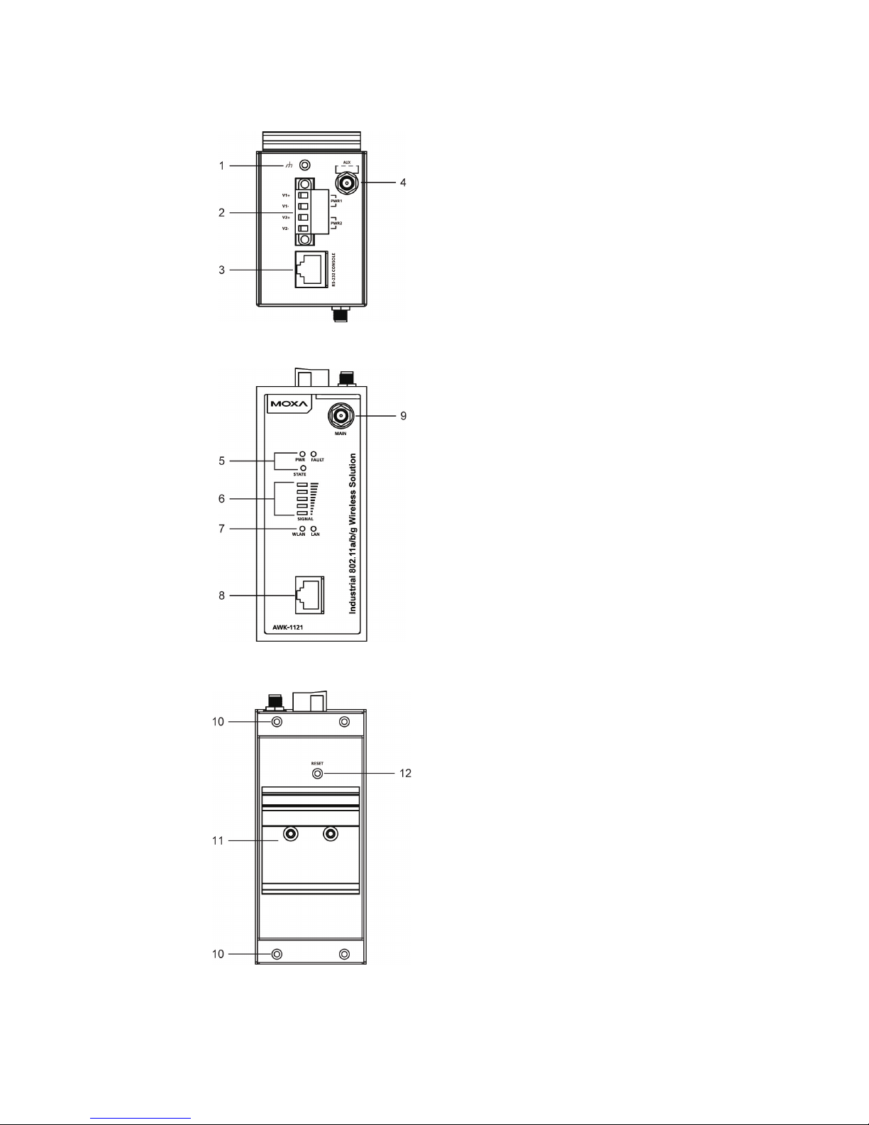
Panel Layout of the AWK-1121
Top Panel View
Front Panel View
Rear Panel View
1. Grounding screw (M3)
2. Terminal block for PWR1 and
PWR2
3. RS-232 console port
4. AUX antenna port
5. System
LEDs: PWR, FAULT, and
STATE LEDs
6. LEDs for signal strength
7. WLAN and LAN LEDs
8. 10/100BaseT(X) RJ45 Port
9. MAIN antenna port
10.
Screw hole for wall-
mounting kit
11.
DIN-rail mounting kit
12.
Reset button
Page 4
- 4 -
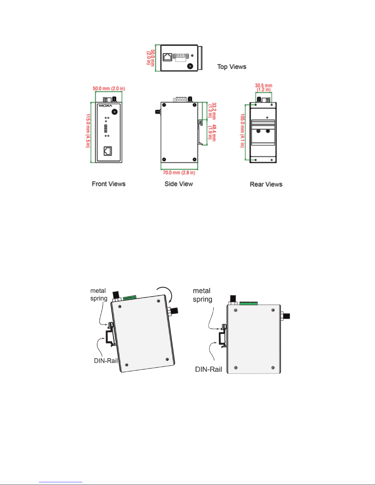
Mounting Dimensions
DIN-Rail Mounting
The aluminum DIN-rail attachment plate should be fixed to the back panel
of the AWK-1121 when you take it out of the box. If you need to reattach
the DIN-rail attachment plate to the AWK-1121, make sure the stiff metal
spring is situated towards the top, as shown in the figures below:
STEP 1:
Insert the top of the DIN rail into the
slot just below the stiff metal spring
in the upper hook of the DIN
-rail
mounting kit.
STEP 2:
Push the AWK
-1121 towards the
DIN rail until the DIN
-rail
attachment bracket snaps into
place.
To remove the AWK-1121 from the DIN rail, simply reverse Steps 1 and 2.
Page 5

- 5 -
Wall Mounting (optional)
For some applications, it may be more convenient to mount the
AWK-1121 to a wall, as illustrated below.
STEP 1:
Remove the aluminum
DIN
-rail attachment plate
from the AWK
-1121, and
then attach the wall mount
plates with M3 screws, as
shown in the adjacent
diagrams.
STEP 2:
Mounting the AWK
-1121 to a wall requires 4 screws.
Use the AWK
-1121 device, with wall mount plates
attached, as a guide to mark the correct locations of
the 4 screws. The heads of the screws should be less
than 6.0 mm in diameter, and the
shafts should be
less
than 3.5 mm in diameter, as shown in the figure
on
the
right.
Do not drive the screws in all the way into the wall—leave a space of about
2 mm to allow room for sliding the wall mount panel between the wall and
the screws.
NOTE
Test the screw head and shank size by inserting the screw into
one of the k
eyhole shaped apertures of the wall-mounting p
lates
before attaching the plate to the wall.
STEP 3:
Once the screws are fixed into
the wall, insert the four screw
heads through the large opening
of
the keyhole-shaped
apertures, and then slide the
AWK
-1121 downwards, as
indicated to the right. Tighten
the four screws for added
stability.
Page 6

- 6 -
Deployment Precautions
Wiring Requirements
WARNING
Safety First!
Be sure to
disconnect the power cord before installing and/or
wiring your Moxa AWK-1121.
WARNING
Safety First!
Calculate the maximum possible current in each power wire and
common wire. Observe all electrical codes dictating the
maximum current allow
able for each wire size.
If the current goes
above
the maximum ratings, the wiring could
overheat, causing
serious damage to your equipment.
You should also pay attention to the following items:
• Use separate paths to route wiring for power and devices. If power
wiring and device wiring paths must cross, make sure the wires are
perpendicular at the intersection point.
NOTE
Do not run signal or communications wiring and power wiring in
the same wire conduit. To avoid interference, wires with different
signal characteristics should be routed separately.
• You can use the type of signal transmitted through a wire to
determine which wires should be kept separate. The rule of thumb is
that wiring with similar electrical characteristics can be bundled
together.
• Keep input wiring and output wiring separate.
• It is strongly advised that you label wiring to all devices in the system
for easy identification.
ATTENTION
This pr
oduct is intended to be supplied by a Listed Power Unit
marked
“Class 2” or “LPS” and rated O/P:
12 to 48 VDC, 0.16 to
0.55 A.
ATTENTION
Make sure
the external power adapte
r (includes power cords and
plug assemblies) provided with the unit is certified and suitable
for use in your country.
Page 7

- 7 -
Grounding the Moxa AWK-1121
Grounding and wire routing help limit the effects of noise due to
electromagnetic interference (EMI). Run the ground connection from the
ground screw to the grounding surface prior to connecting devices.
ATTENTION
This product is intended to be mounted to a well
-grounded
mounting surface, such as a metal panel.
Installations with Unstable Power Inputs
There are cases where the device has to be wired to the same power
source as other equipment. In such cases if equipment such as motors
that are connected in the circuit draw a large amount of current during
operation, the transient voltage drop could potentially cause the AWK to
become unstable. Installing a DC/DC power isolator in between the two
equipment is recommended to isolate the transient effect and to ensure a
stable power input for the AWK.
Installations with Cable Extended Antennas for Outdoor
Applications
If the antenna or the AWK device is installed outdoors or in an open-air
setting, proper lightning protection is required to prevent direct lightning
strikes on the AWK device. In order to prevent coupling currents from
nearby lightning strikes, a lightning arrester should be installed as part of
your antenna system. Ground the device, antenna, as well as the arrester
properly to provide maximum outdoor protection for the device.
Page 8

- 8 -
Arrester Accessories
• SA-NMNF-01: Surge arrester, N-type (male) to N-type (female)
• SA-NFNF-01: Surge arrester, N-type (female) to N-type (female)
Wiring the Redundant Power Inputs
The 4-contact terminal block connector on the AWK-1121’s top panel is
used for the AWK-1121’s two DC inputs. The top and front views of the
terminal block connector are shown here.
Top View
Front View
STEP 1: Insert the negative/positive DC wires
into the
V-/V+ terminals.
STEP 2:
To keep the DC wires from pulling
loose,
use a small flat
-blade screwdriver to
tighten the
wire
-clamp screws on the front of the terminal
block connector.
STEP 3:
Insert the plastic terminal block
connector prongs into the terminal block
receptor, which is
located on the AWK-1121’s t
op
panel.
ATTENTION
If the AWK
-1121 is connected to a motor or other similar type
of
equipment, be sure to use power isolation protection. Before
connecting the
AWK-1121
to the DC power inputs, make sure the
DC power source voltage is stable.
Page 9

- 9 -
Communication Connections
10/100BaseT(X) Ethernet Port Connection
The 10/100BaseT(X) ports located on the AWK-1121’s front panel are
used to connect to Ethernet-enabled devices.
The pinouts for both MDI (NIC-type) ports and MDI-X (HUB/Switch-type)
ports are shown below:
MDI Port Pinouts
MDI-X Port Pinouts
8-pin RJ45
Pin
Signal
Pin
Signal
1
Tx+
1
Rx+
2
Tx- 2 Rx-
3
Rx+
3
Tx+
6
Rx- 6 Tx-
RS-232 Connection
The AWK-1121 has one RS-232 (8-pin RJ45) console port located on the
top panel. Use either an RJ45-to-DB9 or RJ45-to-DB25 cable to connect
the Moxa AWK-1121’s console port to your PC’s COM port. You may then
use a console terminal program to access the AWK-1121 for console
configuration.
Console Pinouts for 10-pin or 8-pin RJ45
10-Pin
Description
8-Pin 1 –
– 2 DSR
1 3 RTS
2 4 GND
3 5 TxD
4 6 RxD
5 7 DCD
6 8 CTS
7 9 DTR
8
10 – –
NOTE
1. The pin numbers for DB9 and DB25 male connectors, and
hole numbers for DB9 and DB25 female connectors are
labeled on the connector strip. However, the numbers are
typically quite small, so you may need to use a magnifying
glass to see the numbers clearly.
2. The pin numbers for both the 8-pin and 10-pin RJ45
connectors (and ports) are typically not labeled on the
connector (or port). Refer to the pinout diagram above
for
details.
Page 10

- 10 -
LED Indicators
The front panel of the Moxa AWK-1121 contains several LED indicators.
The function of each LED is described in the table below:
LED
Color
State
Description
PWR Green
On
Power is on.
Off
Power is not being supplied.
FAULT Red
On
System is booting up.
Blinking
(slow at
1-second
intervals)
IP address cannot be got from DHCP
server.
Blinking
(fast at
0.5-second
intervals)
IP address conflict.
Off
Status is normal.
STATE
Green/
Red
Green
System startup is complete and the
system is in operation.
Green
(Blinking at
1-second
intervals)
The AWK Search Utility has located
the AWK.
Red
System is booting up.
SIGNAL
(5 LEDs)
Green
On
Signal level.
Off
Reserved.
WLAN Green
On
WLAN is connected.
Blinking
WLAN is transferring data.
Off
WLAN is not in use or not working
properly.
LAN Green
Green
100/10 Mbps LAN port is active.
Blinking
Data is being transmitted.
Off
100/10 Mbps LAN port is inactive.
Specifications
WLAN Interface
Standards
IEEE 802.11a/b/g for Wireless LAN
IEEE 802.11i for Wireless Security
IEEE 802.3 for 10BaseT
IEEE 802.3u 10/100BaseT(X)
IEEE 802.3af for Power-over-Ethernet (PoE
models only)
IEEE 802.1D for Spanning Tree Protocol
IEEE 802.1w for Rapid STP
Spread Spectrum and
Modulation (typical)
• DSSS with DBPSK, DQPSK, CCK
• OFDM with BPSK, QPSK, 16QAM, 64QAM
• 802.11b:
CCK @ 11/5.5 Mbps, DQPSK @ 2 Mbps,
DBPSK @ 11 Mbps
• 802.11a/g:
64QAM @ 54/48 Mbps, 16QAM @ 36/24 Mbps
,
QPSK @ 18/12 Mbps, BPSK @ 9/6 Mbps
Page 11

- 11 -
Operating Channels
(central frequency)
US:
• 2.412 to 2.462 GHz (11 channels)
• 5.18 to 5.24 GHz (4 channels)
EU:
• 2.412 to 2.472 GHz (13 channels)
• 5.18 to 5.24 GHz (4 channels)
JP:
• 2.412 to 2.472 GHz (13 channels, OFDM)
• 2.412 to 2.484 GHz (14 channels, DSSS)
• 5.18 to 5.24 GHz (4 channels for W52)
Security
Firewall for MAC/IP/Protocol/Port-based filtering
64-bit and 128-bit WEP encryption,
WPA/WPA2-Personal and Enterprise (IEEE
802.1X/RADIUS, TKIP, and AES)
Transmission Rates
802.11b: 1, 2, 5.5, 11 Mbps
802.11a/g: 6, 9, 12, 18, 24, 36, 48, 54 Mbps
TX Transmit Power
802.11b:
• Typ. 18±1.5 dBm @ 1 to 11 Mbps
802.11g:
• Typ. 18±1.5 dBm @ 6 to 24 Mbps
• Typ. 17±1.5 dBm @ 36 Mbps
• Typ. 16±1.5 dBm @ 48 Mbps
• Typ. 16±1.5 dBm @ 54 Mbps
802.11a:
• Typ. 18±1.5 dBm @ 6 to 24 Mbps
• Typ. 16±1.5 dBm @ 36 Mbps
• Typ. 15±1.5 dBm @ 48 Mbps
• Typ. 14±1.5 dBm @ 54 Mbps
RX Sensitivity
802.11b:
• -97 dBm @ 1 Mbps
• -94 dBm @ 2 Mbps
• -92 dBm @ 5.5 Mbps
• -90 dBm @ 11 Mbps
802.11g:
• -88 dBm @ 6 to 24 Mbps
• -85 dBm @ 36 Mbps
• -75 dBm @ 48 Mbps
• -70 dBm @ 54 Mbps
802.11a:
• -88 dBm @ 6 to 24 Mbps
• -85 dBm @ 36 Mbps
• -75 dBm @ 48 Mbps
• -70 dBm @ 54 Mbps
Protocol Support
General Protocols
Proxy ARP, DNS, HTTP, HTTPS, IP, ICMP, SNTP,
TCP, UDP, RADIUS, SNMP, PPPoE, DHCP
Interface
Default Antennas 1 dual-band omni-directional antennas, 2 dBi,
RP-SMA (male)
Connector for
External Antennas
RP-SMA (female)
RJ45 Ports
1, 10/100BaseT(X) auto negotiation speed, F/H
duplex mode, and auto MDI/MDI-X connection
Page 12

- 12 -
Console Port
RS-232 (RJ45-type)
Reset
Present
LED Indicators
PWR, FAULT, STATE, SIGNAL, WLAN, LAN
Physical Characteristics
Housing
Metal, providing IP30 protection
Weight
400 g (0.9 lb)
Dimensions
50 x 115 x 70 mm
(1.98 x 4.53 x 2.76 in)
Installation
DIN-rail mounting,
wall mounting (with optional kit)
Environmental Limits
Operating
Temperature
Standard Models: 0 to 60°C (32 to 140°F)
Wide Temp. Models: -40 to 75°C (-40 to 167°F)
Storage Temperature
-40 to 85°C (-40 to 185°F)
Ambient Relative
Humidity
5% to 95% (non-condensing)
Power Requirements
Input Voltage
12 to 48 VDC, redundant dual DC power inputs or
48 VDC Power-over-Ethernet (IEEE 802.3af
compliant)*
*PoE is only available for the AWK-1121-PoE
Connector
4-pin removable terminal block
Power Consumption
12 to 48 VDC, 0.16 to 0.55 A
Reverse Polarity
Protection
Present
Standards and Certifications
Safety
UL 60950-1, EN 60950-1
EMC
EN 301 489-1/17; FCC Part 15, Subpart B Class B;
EN 55022/55024
Radio EN 300 328, EN 301 893, TELEC, FCC ID
SLE-WAPN003
Note: Please check Moxa’s website for the most up-to-date
certification status.
Reliability
MTBF
392,209 hrs.
Warranty
Warranty Period
5 years
Details
See www.moxa.com/support/warranty.aspx
ATTENTION
The AWK
-1121 is NOT a portable mobile device and should be
located
at least 20 cm away from the human body.
The AWK
-1121 is NOT designed for the general public. A
well
-trained technician is required to deploy the AWK-4131A
units and safely establish a wireless network.
Page 13

- 13 -
ATTENTION
This device complies with Part 15 of the FCC rules.
Operation is subject to the following conditions:
1. This device may not cause harmful interference.
2. This device must accept any interference received,
including interference that may cause undesired operation.
ATTENTION
Do not locate the antenna near overhead power lines or other
electric light or power circuits, or where it can come into contact
with such circuits.
When installing the antenna, take extreme
care not to come into contact with such circuits, because they
may cause serious injury or death. For proper installation and
grounding of the antenna, refer to national and local codes (for
example, U.S.: NFPA 70
; National Electrical Code (NEC) Article
810; Canada: Canadian Electrical Code, Section 54).
NOTE
For installation flexibility, either the MAIN antenna (on the front
panel) or the AUX antenna (on the top panel) may be selected for
use. Make sure the ante
nna connection matches the antenna
configured in the AWK
-1121web interface.
To protect the connectors and RF module, all radio ports should
be terminated by either an antenna or a terminator. We strongly
recommend using resistive terminators for terminatin
g the
unused antenna ports.
ATTENTION
 Loading...