

Page 1

A50/A51/A60
Feb. 1997 ( 1st Edition )
All Rights Reserved
Page 2

Part I - A50/A51 RS-232 to RS-422/RS-485 Converter
A50/A51
RS-232 to RS-422/RS-485
Bidirectional Converter
Page 3

Part II - A60 RS-232 Surge Protection
A60
RS-232 Surge Protection
Converter
Page 4
Copyright Notice
This documentation is copyrighted by Moxa Technologies Co., Ltd.
All rights are reserved. Moxa Technologies reserves the right to
make improvements to the products described in this manual at any
time without notice.
Information provided in this manual is intended to be accurate and
reliable. However, Moxa Technologies assumes no responsibility for
its use, nor for any infringements of rights of the fourth party which
may result from its use.
MOXA is a registered trademark of Moxa Technologies Co., Ltd.
The other trademarks in this manual belong to their manufacturers
individually.
Moxa Technologies Co., Ltd.
Tel: +866-2-8665-6373
Fax: +886-2-8665-6372
www.moxa.com.tw
support@moxa.com.tw
Page 5

MoxaInternetService
s
Customer’s satisfaction is always our number one concern. To
ensure customers get the full benefit of our services, Moxa Internet
Services (MIS) have been built for technical support, product inquiry,
new driver upgrade, etc.
The followings are the services we provide.
E-mail for technical support
address : support@moxa.com.tw
Ftp site for free driver upgrade
address : ftp.moxa.com or ftp.moxa.com.tw
user ID : ftp
password : your_email_address
World Wide Web (WWW) for product info.
address : www.moxa.com or www.moxa.com.tw
Page 6

Table of Contents
Part I - A50/A51 RS-232 to RS-422/RS-485 Converter
Chapter 1. Introduction ………………………………………. 1
1.1 Overview 1
1.2 Features and Specifications 2
1.3 Package Check List 5
Chapter 2. Installation ……………………………………….. 7
2.1 Installation Procedure 7
2.2 Switch Function Description 7
2.3 LED Indicators 8
2.4 RS-422/RS-485 Pinouts 9
Chapter 3. Operation ………………………………………… 11
3.1 Point-to-point 12
3.2 Multidrop 14
3.3 Simplex/Transmit, Receive 17
3.4 Self Test 19
Appendix A RS-232 Pinouts and Cable Wiring ……………….. 21
Appendix B Impedance Matching and Termination Resistors…… 25
Appendix C Troubleshooting …………………………………. 27
Page 7

Table of Contents
Part II - A60 RS-232 Surge Protection
Chapter 1. Introduction…………………………………………… 29
1.1 Overview 30
1.2 Features and Specifications 30
1.3 Package Check List 31
Chapter 2. Installation……………………………………………… 33
2.1 Installation Procedure 33
2.2 LED Indicators 34
2.3 Self Test 36
Appendix A RS-232 Pinouts and Cable Wiring…………………… 37
Appendix B Troubleshooting ……………………………………….. 41
Page 8

Page 9
Chapter1 Introduction
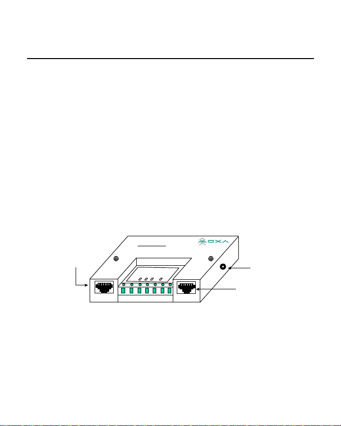
1.1 Overview
The MOXA RS-232 to RS-422/RS-485 bidirectional converters,
A50 and A51, are designed to convert unbalanced (single-ended)
RS-232 signals to balanced (differential) RS-422/RS-485
signals, and vice versa. They are the best choices for those who
want to control devices at longer distance and/or to
communicate with several devices via merely one link,
particularly in the industry area. Point-to-point, multidrop and
simplex operations are available for most users' needs.
RS-422/485
RJ-45 Connector
RS-232toRS-422/485
A50
onverter
C
R
R
T
P
T
X
X
W
S
D
D
RS-422/485 RS-232
R
Outlook of A50
1
Power Jack
RS-232
RJ-45 Connector
Page 10
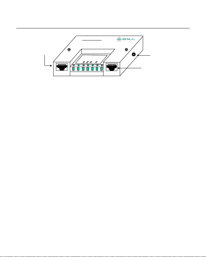
Introduction Chapter 1
IsolatedRS-232toRS-422/485
RS-422/485
RJ-45 Connector
RS-422/485 RS-232
A51
C
A51
onverter
R
R
T
X
T
X
S
D
D
P
W
R
Power Jack
RS-232
RJ-45 Connector
Outlook of A51
1.2 Features and Specifications
Features
Both A50 and A51 are RS-232 to RS-422/RS-485 bidirectional
converters except that A51 has one more feature: isolation
protection, which provides high voltage protection up to 2000V.
All the switches, SW1 and SW2, of A50/A51 are designed to be
inside of the converter to protect switch settings from
unintended change and introducing communication error
without any warning. Hence, it is necessary to take the two
screws off and open the cover up if you need to change the
operation mode via sliding the switches.
The A50/A51 must be powered either from a DC +9V to +30V,
2
Page 11

Chapter 1 Introduction
150mA power adapter or the pin 6 and pin 7 of the Terminal
Block.
LED indicators are provided to show the status of data
transmitting/receiving, RTS signal and Power.
To avoid over-current from the remote ground to converter's
ground, an protect resistor has been added inside the A50/A51.
Specifications
v Power Supply - DC +9V to +30V, 150mA
v Data Rate - Up to 921600 bps under 500 ft (0.15 Km)
v Distance - Up to 4000 ft (1.2 Km) under 115200 bps
v RS-232 RJ-45 Connector -
Supports TxD, RxD, DTR, DSR, RTS, CTS, DCD, GND
v RS-422/RS-485 RJ-45 Connector -
Supports TxDA, TxDB, RxDA, RxDB, GND
v RS-422/RS-485 Terminal Block Connector -
Supports TxDA, TxDB, RxDA, RxDB, GND, PWR, PWR
GND
v Switch - SW1 : for full/half-duplex mode
SW2 : for Tx (driver) and Rx (receiver) state
3
Page 12
Introduction Chapter 1
C
v Isolation Protection - for A51 only, up to 2000V.
v Ter minal Resistor - RT1 space reserved for RS-422/RS-485
receiver signal.
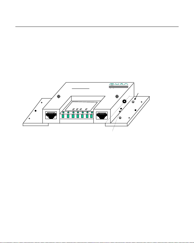
v Mounting Kit - Plastic Plates and screws for mounting
A50/A51 on the wall or any surface.
RS-232toRS-422/485
A50
onverter
R
R
T
P
T
X
X
W
S
D
D
RS-422/485 RS-232
R
Fixing Screw
A50/A51 with Mounting Kit
4
Mounting
Screw
Page 13

Chapter 1 Introduction
1.3 Package Check List
Upon unpacking your A50 or A51 package, you should find the
following items:
v A50 (or A51) RS-232 to RS-422/RS-485 bidirectional
converter (with isolation protection if A51)
v One power adapter
v Mounting Kit
v A50/A51/A60 User's Manual
5
Page 14

Introduction Chapter 1
6
Page 15
Chapter 2 Installation
2.1 Installation Procedure
As RS-232 or RS-422/RS-485 port are labeled clearly on the
surface of the A50/A51 converter, please prepare the RS-232
cable (refer to Appendix A, RS-232 Cable Wiring) and decide
the operation mode as well as 2/4-wire cable (refer to Chapter 3,
Operation) in advance.
Take off the two screws on top of the converter and open the
cover up if you need to change the operation mode via sliding
the switches.
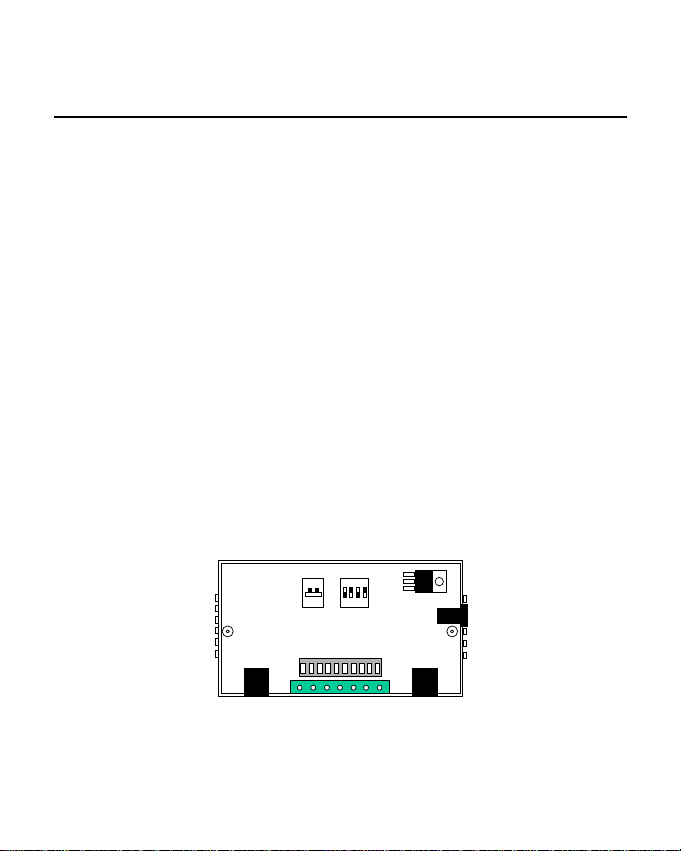
2.2 Switch Function Description
ON
ON
1
1 2 3 4
SW1 SW2
Inside look of A50/A51
7
Page 16

Chapter 2 l l Installation
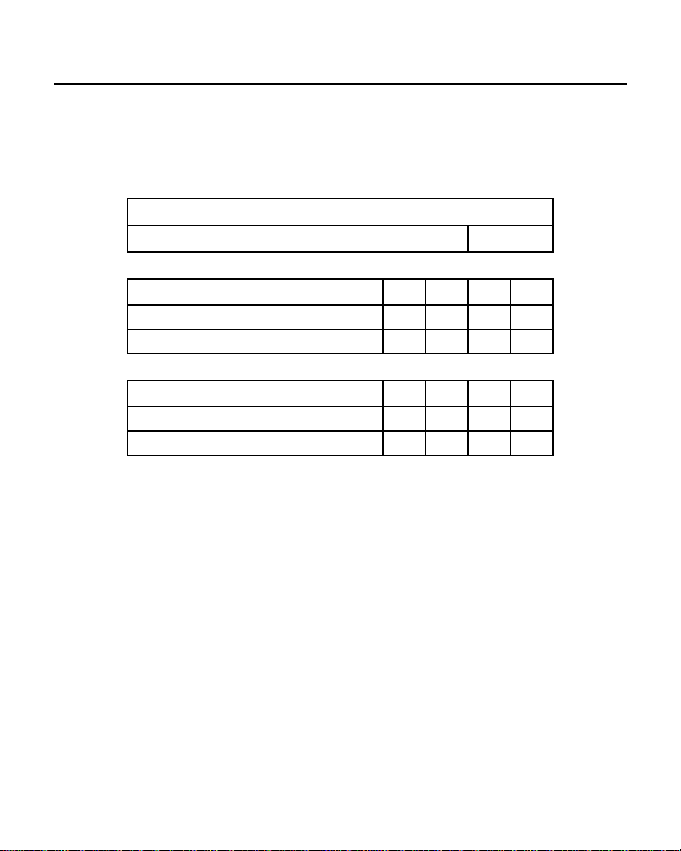
Switch settings table of SW1 and SW2 is as follows:
SW1
*Full-duplex mode Off
Half-duplex mode On
SW2 Pin1 Pin2 Pin3 Pin4
*TxD always enabled On Off X X
TxD always disabled Off Off X X
TxD enabled by RTS Off On X X
*RxD always enabled X X On Off
RxD enabled by /RTS X X Off On
Note: ‘ * ‘ means default settings , ‘ X ‘ means don’t care
2.3 LED Indicators
There are LED indicators for TxD, RxD, RTS, and PWR on top
of A50/A51. The indicator is not lighted on when not connected
with signal or power. On the contrary, it will be lighted on and
be in one of the red, green or orange colors.
TxD indicator stands for data transmitting from RS-232 to
RS-422/RS-485. It shows green when connected and no data
transmitting. It shows orange when connected and transmitting
data.
8
Page 17

Installation l l Chapter 2
RxD indicator stands for data transmitting from RS-422/RS-485
to RS-232. It shows red when connected and no data received. It
shows orange when connected and receiving data (In halfduplex mode, it shows red when line is not connected due to the
characteristics of ICs for RS-485).
RTS indicator is for RS-232 RTS signal. It shows red when
connected and RTS signal turned on. It shows green when
connected and RTS signal turned off.
PWR indicator is red when power is on and not lighted when
power is off or not connected.
2.4 RS-422/RS-485 Pinouts
RS-422/RS-485 interface with RJ-45 Jack connector or
Terminal Block Connector is depicted as follows.
RJ-45 Connector Terminal Block Connector
1 2 3 4 5 6 7 8 9 10
1 2 3 4 5 6 7
9
Page 18

Chapter 2 l l Installation
A50/A51 A50/A51
RJ-45 Jack Terminal Block
Connector Pinouts Signals Connector Pinouts Signals
1 nc 1 TxD B
2 nc 2 TxD A
3 GND 3 RxD B
4 TxD B 4 RxD A
5 TxD A 5 GND
6 RxD A 6 Power GND
7 RxD B 7 Power Input
8 GND
9 nc
10 nc(not connected)
Note : Pin 6 and Pin 7 of Terminal Block are for Power GND
and Power Input, which is an alternate option for power
adapter. Be careful that DO NOT confuse RS-422/RS485 GND with Power GND.
Note : Under half-duplex mode (SW1 in ON mode), the
couples of (TxD B, RxD B) and (TxD A, RxD A) are
shorted inside the converter for convenience. Users can
save the trouble with shorting the wires.
10
Page 19

Chapter 3 Operation
The A50 (or A51) supports 5 kinds of operations. They are:
v Point-to-point/4-wire Full Duplex
v Point-to-point/2-wire Half Duplex
v Multidrop/4-wire Full Duplex
v Multidrop/2-wire Half Duplex
v Simplex/Transmit, Receive Only
All the operations are to be described below. And TA, TB, RA
and RB represent TxD A, TxD B, RxD A and RxD B signal
lines of the RJ-45 RS-422/RS-485 connector or the Terminal
Block, respectively.
Note : If possible, connect GND of both sides together to gain
better signals. That is, you may need one more GND
connection in addition to 4-wire or 2-wire connection.
Note : For A51, connecting GND at the Terminal Block to the
earth ground to provide a ground path to prevent
electric shock caused by lightning, no matter RJ-45 or
Terminal Block RS-422/RS-485 is used.
~11~
Page 20

Chapter 3 l l Operation
3.1 Point-to-point
Point-to-point configuration means two devices which locate at
two different places can be linked together to communicate
through a couple of A50 (or A51) converters.
4-wire Full Duplex
A50/A51A50/A51
TA
DTE/
DCE
RS-232
RS-422/ TB
RS-485 RB
RA
GND
In the graph, TA, TB, RA and RB could be either from RJ-45 or
Terminal Block. The settings of the switches for each A50 (or
A51) are as follows:
SW1 SW2 Pin1 Pin2 Pin3 Pin4
Full-duplex mode Off TxD always enabled On Off X X
RxD always enabled X X On Off
RA
RB RS-422/ RS-232
TB RS-485
TA
GND
DTE/
DCE
12
Page 21

Operation l l Chapter 3
2-wire Half Duplex
A50/A51
RA
RB RS-232
TB
TA
GND
RS-485
DTE/
DCE
DTE/
DCE
RS-232
A50/A51
TA
TB
RB
RA
GND
RS-485
In the graph, TA, TB, RA and RB could be either from RJ-45 or
Terminal Block. The settings of the switches for each A50 (or
A51) are as follows:
SW1 SW2 Pin1 Pin2 Pin3 Pin4
Half-duplex mode On TxD enabled by RTS Off On X X
RxD enabled by / RTS X X Off On
13
Page 22

Chapter 3 l l Operation
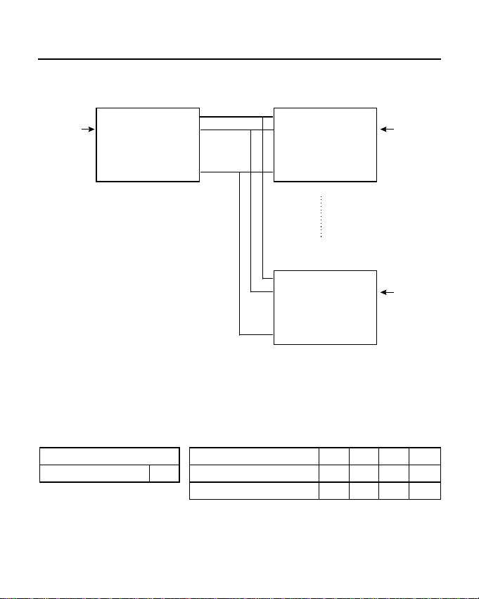
3.2 Multidrop
Multidrop configuration means that more than two devices
(Max. 10 for RS-422; Max. 32 for RS-485) can be linked all
together to communicate one another through many A50 (or
A51) devices. In this configuration, one of the A50 (or A51)
will be connected to a master devic e and the rest of A50 (or
A51) devices will be connected to any other slave devices.
4-wire Full Duplex
Master
DTE/
DCE
RS-232
A50/A51
TA
RS-485 TB
RB
RA
GND
RA
RB RS-485 RS-232
TB
TA
GND
RA
RB RS-485 RS-232
TB
TA
GND
14
A50/A51
A50/A51
Slave
DTE/
DCE
Slave
DTE/
DCE
Page 23
Operation l l Chapter 3
In the graph, TA, TB, RA and RB could be either from RJ-45 or
Terminal Blocks. The settings of the switches for each A50 (or
A51) are as follows:
SW1
Full-duplex mode Off
SW2 for Master Pin1 Pin2 Pin3 Pin4
TxD always enabled On Off X X
RxD always enabled X X On Off
SW2 for Slaves Pin1 Pin2 Pin3 Pin4
TxD enabled by RTS Off On X X
RxD always enabled X X On Off
2-wire Half Duplex
15
Page 24

Chapter 3 l l Operation
Master
DTE/
DCE
A50/A51
RA
RS-232
RS-485 RS-485
TB
RB
TA
GND
RA
RB RS-232
TB
TA
GND
RA
RB RS-232
TB
TA
GND
A50/A51
A50/A51
RS-485
Slave
DTE/
DCE
Slave
DTE/
DCE
16
Page 25

Operation l l Chapter 3
In the graph, TA, TB, RA and RB could be either from RJ-45 or
Terminal Block. The settings of the switches for each A50 (or
A51) are as follows:
SW1 SW2 Pin1 Pin2 Pin3 Pin4
Half-duplex mode
On
TxD enabled by RTS Off On X X
RxD enabled by / RTS X X Off On
3.3 Simplex/Transmit, Receive
Simplex configuration means that more than two devices
(Max. 10 for RS-422; Max. 32 for RS-485) can be linked all
together to communicate through many A50/A51 devices. Its
configuration is like the Multidrop's, but the master device can
talk only and the slave devices can listen only.
17
Page 26
Chapter 3 l l Operation
DTE/
DCE
RS-232
A50/A51
TA
RS-422/ TB
RS-485 RB
RA
GND
A50/A51
RA
RB RS-422/ RS-232
TB RS-485
TA
GND
DTE/
DCE
A50/A51
RA
RB RS-422/ RS-232
TB RS-485
TA
GND
DTE/
DCE
In the graph, TA, TB, RA and RB could be either from RJ-45 or
Terminal Block. The settings of the switches for each A50 (or
A51) are as follows:
SW1 SW2 Pin1 Pin2 Pin3 Pin4
Full-duplex mode Off TxD always enabled On Off X X
RxD always enabled X X On Off
18
Page 27

Operation l l Chapter 3
3.4 Self Test
This configuration is for A50/A51 self test. Run terminal
emulation program to see if what you received is what you
typed.
A50/A51
TA
DTE/
DCE
RS-232
RS-422/485
In the graph, TA, TB, RA and RB could be either from RJ-45 or
Terminal Block. The settings of the switches for each A50 (or
A51) are as follows:
SW1 SW2 Pin1 Pin2 Pin3 Pin4
Half-duplex mode On TxD always enabled On Off X X
RxD always enabled X X On Off
TB
RB
RA
GND
19
Page 28

Chapter 3 l l Operation
20
Page 29

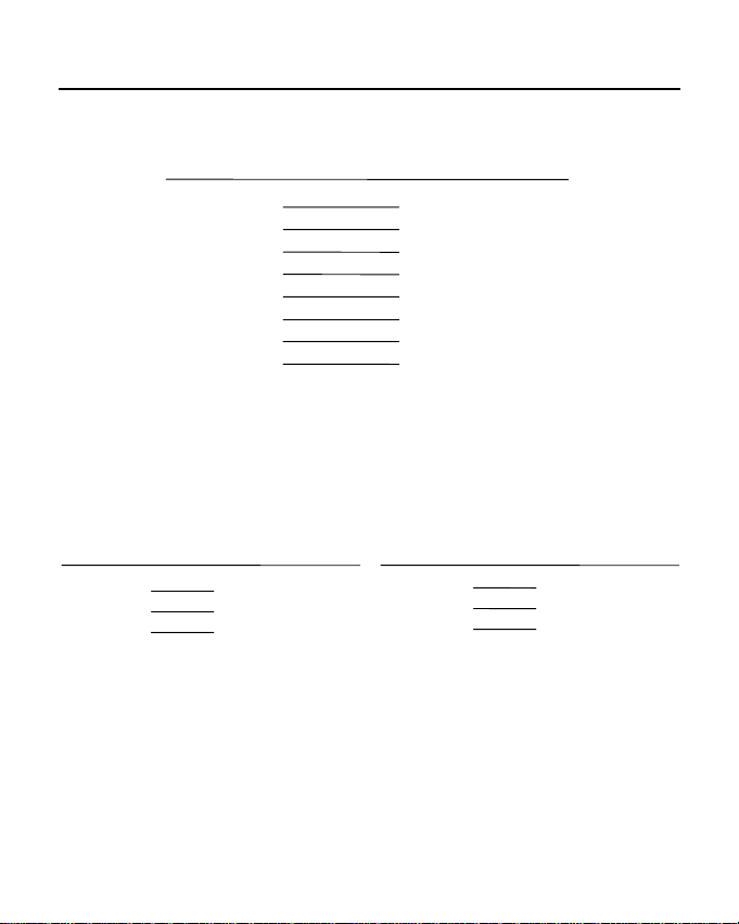
Appendix A RS-232 Pinouts & Cable Wiring
RS-232 interface with RJ-45 connector is depicted as follows.
RJ-45 Connector
1 2 3 4 5 6 7 8 9 10
A50/A51 RJ-45
Connector Pinouts RS-232 Signals
1 DCD Always On
2 DSR
3 RTS
4 GND
5 TxD
6 RxD
7 GND
8 CTS
9 DTR
10 -
~21~
Page 30

Appendix A l l RS-232 Pinouts and Cable Wiring
Note : Each group of (RTS, CTS) and (DTR, DSR) pins have
been shorted on A50/A51, which release the users from
the hardware flow control cable wiring problem. Thus,
there are two types of RS-232 cable wiring which are
listed below.
Type 1:To connect RS-232 side of A50/A51 to a DTE (e.g. PC
COM1/2) or DCE . (Please check the precise DTE/DCE
pinouts, the following DTE/DCE pinouts is just an
example)
A50/A51 DTE A50/A51 DTE
RJ-45 Connector DB-25 Male RJ-45 Connector DB-9 Male
1 DCD 8 DCD 1 DCD 1 DCD
2 DSR 20 DTR 2 DSR 4 DTR
3 RTS 5 CTS 3 RTS 8 CTS
5 TxD 3 RxD 5 TxD 2 RxD
6 RxD 2 TxD 6 RxD 3 TxD
7 GND 7 GND 7 GND 5 GND
8 CTS 4 RTS 8 CTS 7 RTS
9 DTR 6 DSR 9 DTR 6 DSR
22
Page 31
RS-232 Pinouts and Cable Wiring l l Appendix A
A50/A51 DCE
RJ-45 Connector DB-25 Female
1 DCD 8 DCD
2 DSR 6 DTR
3 RTS 4 CTS
5 TxD 2 RxD
6 RxD 3 TxD
7 GND 7 GND
8 CTS 5 RTS
9 DTR 20 DSR
Type 2: To connect RS-232 side of A50/A51 to a DTE, e.g.
terminal or PC COM1/2, with 3-pin wiring if don't
care Hardware flow control.
A50/A51 DTE A50/A51 DTE
RJ-45 Connector DB-25 Male RJ-45 Connector DB-9 Male
5 TxD 3 RxD 5 TxD 2 RxD
6 RxD 2 TxD 6 RxD 3 TxD
7 GND 7 GND 7 GND 5 GND
3 RTS 5 CTS 3 RTS 8 CTS
8 CTS 4 RTS 8 CTS 7 RTS
2 DSR 20 DTR 2 DSR 4 DTR
9 DTR 6 DSR 9 DTR 6 DSR
1 DCD 8 DCD 1 DCD 1 DCD
23
Page 32

Appendix A l l RS-232 Pinouts and Cable Wiring
A50/A51 DCE
RJ-45 Connector DB-25 Female
5 TxD 2 RxD
6 RxD 3 TxD
7 GND 7 GND
3 RTS 4 CTS
8 CTS 5 RTS
2 DSR 6 DTR
9 DTR 20 DSR
1 DCD 8 DCD
24
Page 33

A p p e n d ix B I m p e d a n ce Matc h ing a n d Termin atio n R esistors
When an electrical signal travels through two different
resistance junctions in a transmission line, the mismatch will
sometimes cause signal reflection. Signal reflection causes
signal distortion, which in turn will contribute communication
errors. The solution to this problem is to establish the same
impedance at the line ends as in the line itself by terminating
them with resistors.
It is normally sufficient when the value of the termination
resistor equals the characteri stic impedance of the transmission
line. The resistors should be added near the receiving side. For
example,
A50/A51 Remote site
TxDA RxDA
TxDB RxDB
RxDA TxDA
RxDB TxDB
~25~
Page 34

Appendix Bl l Impedance Matching and Termination Resistors
Note:
1. stands for termination resistor near the receiving
side. RT1 is the space reserved inside A50/A51 for
this purpose.
2. The suggested termination resistor for AWG #26
cable is 100 ohm.
3. The suggested termination resistor for phone cable is
600 ohm.
26
Page 35

Appendix C Troubleshooting
Q1. Failure of data transmission.
Solutions:
1. Check that the right power adapter is applied.
2. Check that the RS-232 link is proper.
3. Check that the RS-422/RS-485 link is proper.
4. Check that the SW1 and SW2 are set properly.
Q2. Data loss or error.
Solution:
Check that the data rate, data format are the same for
both devices.
Q3. How do I do self-test on A50/A51?
Solution:
Refer to Chapter 3.4 Self Test .
~27~
Page 36

Appendix C l l Troubleshooting
~28~
Page 37

Chapter 1 Introduction
1.1 Overview
The MOXA RS-232 Surge Protection converter, A60, is
designed to protect the RS-232 communication line from TOV
(Transient Over Voltages) which comes from lightning,
electrostatic discharge and other forms. TOV is always the
major factor which damages components and makes ports
unreliable. To improve this problem, we add Transient Voltage
Suppressor to our I/O ports to clamp surge voltage to protect
ports from TOV.
Due to the impulse signal generated by inductive devices in
factory, the surge protection is best suited for the factory
automation applications.
RS-232 Surge
0
RS-232
RJ-45 Connector
Remote
A6
P
rotection
T R D D R C D
X X T S T T C
D D R R S S D
Local
Power Jack
( Not used )
RS-232
RJ-45 Connector
Outlook of A60
~29~
Page 38

Chapter 1 • • Introduction
1.2 Features and Specifications
Features
A60's main feature is surge protection up to 2000V. No switch
is needed. No power is needed. LED indicators are provided to
show the status of data transmitting/receiving, modem control
signals and DCD.
Specifications
v RS-232 RJ-45 Connectors : supports TxD, RxD, DTR, DSR,
RTS, CTS, GND, DCD
v RS-232 Terminal Block : supports TxD, RxD, DTR, DSR,
RTS, CTS, GND
v LED Indicators : for TxD, RxD, DTR, DSR, RTS, CTS,
DCD
v Surge Protection : up to 2000V, preventing surge from
remote site.
v Mounting Kit : plastic plates and screws for mounting A60
on the wall or any surface.
~30~
Page 39

Introduction • •Chapter 1
Mounting
Screw
Remote
RS-232 Surge
0
6
A
P
rotection
T R D D R C D
X X T S T T C
D D R R S S D
R
R
T
P
T
X
X
W
S
D
D
R
Local
Fixing Screw
A60 with Mounting Kit
1.3 Package Check List
Upon unpacking your A60 package, you should find the
following items:
v A60 RS-232 surge protection converter
v Mounting Kit
v A50/A51/A60 User's Manual
~31~
Page 40

Chapter 1 • • Introduction
~32~
Page 41

hapter 2
C
Installation
2.1 Installation Procedure
Even though the local and remote ports of A60's are labeled on
the surface of the A60 converter, please take care when
connecting the cables to the A60 and the hosts. Note that the
surge from both the local and the remote site is blocked by the
A60. However , the LED indicators and the local host are under
surge protection if and only if the surge comes in from the
remote port of A60. Hence, it is recommended to keep A60 as
close as possible to the local host. Otherwise, you may risk
damaging the A60 itself as well as the local host if surge occurs
between the A60's local port and the host.
In addition, you may need a couple of A60s, if both local and
remote hosts are to be protected from surge.
Note that remote port and Terminal Block are actually the same
except that DCD signal is not available in Terminal Block.
It is recommended to connect GND at the Terminal Block to the
earth ground to provide a ground path to prevent electric shock
caused by lightning, no matter RJ-45 or Terminal Block is used.
~33~
Page 42

Chapter 2 • • Introduction
To
Remote
Host
2000 V Surge
Remote
0
A6
RS-232 Surge
0
A6
Protection
T R D D R C D
X X T S T T C
D D R R S S D
Local
To
Local
Host
Earth Ground
Please prepare the RS-232 cables, referring to Appendix A, RS232 Cable Wiring.
2.2 LED Indicators
There are LED indicators for TxD, RxD, DTR, DSR, RTS, CTS,
and DCD on top of A60. The indicators are not lighted on when
not connected with signals. On the contrary, they will be lighted
on and be one of the red, green or orange colors.
TxD indicator (signal from local port)
Green : when connected correctly and no data transmitting.
Orange : when transmitting data from local to remote site.
~34~
Page 43

Installation • • Chapter 2
RxD indicator (signal from remote port )
Green : when connected correctly and no data receiving.
Orange : when receiving data from remote to local site.
DTR/RTS indicators (signal from local port)
Red : when connected and DTR (or RTS) signal turned on.
Green : when connected and DTR (or RTS) signal turned off.
DSR/CTS/DCD indicators (signal from remote port)
Red : when connected and DSR (or CTS/DCD) signal turned on
Green : when connected and DSR (or CTS/DCD) signal turned off.
~35~
Page 44
Chapter 2 • • Introduction
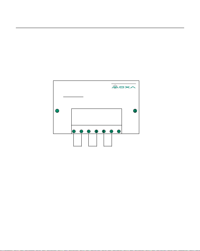
2.3 Self Test
This configuration is for A60 self-test. Run terminal emulation
program to see if what you received is what you typed.
RS-232 Sur ge
0
6
A
P
rotection
R
R
D
D
C
D
T
X
T
S
T
C
S
D
R
R
S
D
Local
Remote
T
X
D
1 2 3 4 5 6 7
In the above graph, all the signal lines could be either from
remote site RJ-45 or Terminal Block and shorted as shown.
~36~
Page 45

ppendix A
A
RS-232 Pinouts and Cable Wiring
Below is RS-232 pinouts for RJ-45 connector or Terminal
Block.
RJ-45 Connector Terminal Block Connector
1 2 3 4 5 6 7 8 9 10
A60 RJ-45 A60 Terminal Block
Connector Pinouts Signals Connector Pinouts Signals
1 DCD 1 TxD
2 DSR 2 RxD
3 RTS 3 DTR
4 GND 4 DSR
5 TxD 5 RTS
6 RxD 6 CTS
7 GND 7 GND
8 CTS
9 DTR
10 -
~37~
1 2 3 4 5 6 7
Page 46

Appendix A • • RS-232 Pinouts and Cable Wiring
There are two types of RS-232 cable wiring which are listed
below.
Note: 1. Terminal Block supports no DCD signal.
2. DTE: Data Terminal Equipment like terminal or PC
COM1/2; DCE: Data Communication Equipment
like modem. Please check the precise DTE/DCE
pinouts, the following DTE/DCE pinouts is just an
example.
Type 1: To connect RS-232 local/remote port of A60 to a DTE
or DCE.
DTE DTE
A60 DB-25 Male A60 DB-9 Male
DCD 8 DCD DCD 1 DCD
DSR 20 DTR DSR 4 DTR
RTS 5 CTS RTS 8 CTS
TxD 3 RxD TxD 2 RxD
RxD 2 TxD RxD 3 TxD
GND 7 GND GND 5 GND
CTS 4 RTS CTS 7 RTS
DTR 6 DSR DTR 6 DSR
~38~
Page 47
RS-232 Pinouts and Cable Wiring • • Appendix A
DCE
A60 DB-25 Female
DCD 8 DCD
DSR 6 DTR
RTS 4 CTS
TxD 2 RxD
RxD 3 TxD
GND 7 GND
CTS 5 RTS
DTR 20 DSR
Type 2: To connect RS-232 local/remote port of A60 to a DTE
with 3-pin wiring if don't care hardware flow control.
DTE DTE
A60 DB-25 Male A60 DB-9 Male
TxD 3 RxD TxD 2 RxD
RxD 2 TxD RxD 3 TxD
GND 7 GND GND 5 GND
RTS 5 CTS RTS 8 CTS
CTS 4 RTS CTS 7 RTS
DSR 20 DTR DSR 4 DTR
DTR 6 DSR DTR 6 DSR
DCD 8 DCD DCD 1 DCD
~39~
Page 48

Appendix A • • RS-232 Pinouts and Cable Wiring
DCE
A60 DB-25 Female
TxD 2 RxD
RxD 3 TxD
GND 7 GND
RTS 4 CTS
CTS 5 RTS
DSR 6 DTR
DTR 20 DSR
DCD 8 DCD
~40~
Page 49

ppendix B
A
Troubleshooting
Q1. Failure of data transmission.
Solutions:
Check that the RS-232 link is proper.
Q2. Data loss or error.
Solution:
1. Check that the data rate, data format are the same
for both devices.
2. Surge occurs during the data transferring. Error
detection and recovery should be taken in
applications.
Q3. How do I do self-test on A50?
Solution:
Refer to Chapter 2.3, Self Test.
 Loading...