

Page 1

Moxa IEEE 802.11a/b/g PCI Module
WAPA004 User’s Manual
www.moxa.com
First Edition, January 2013
© 2013 Moxa Inc. All rights reserved.
Reproduction without permission is prohibited.
Page 2

WAPA004 User’s Manual
The hardware and software described in this manual is furnished under a license agreement and may be used
only in accordance with the terms of that agreement.
Copyright Notice
Copyright © 2009 Moxa Inc.
All rights reserved.
Reproduction without permission is prohibited.
Trademarks
MOXA is a registered trademark of Moxa Inc.
All other trademarks or registered marks in this manual belong to their respective manufacturers.
Disclaimer
Information in this document is subject to change without notice and does not represent a commitment on the
part of Moxa.
Moxa provides this document “as is,” without warranty of any kind, either expressed or implied, including, but
not limited to, its particular purpose. Moxa reserves the right to make improvements and/or changes to this
manual, or to the products and/or the programs described in this manual, at any time.
Information provided in this manual is intended to be accurate and reliable. However, Moxa assumes no
responsibility for its use, or for any infringements on the rights of third parties that may result from its use.
This product might include unintentional technical or typographical errors. Changes are periodically made to the
information herein to correct such errors, and these changes are incorporated into new editions of the
publication.
Technical Support Contact Information
www.moxa.com/support
Moxa Americas:
Toll-free: 1-888-669-2872
Tel: +1-714-528-6777
Fax: +1-714-528-6778
Moxa Europe
Tel: +49-89-3 70 03 99-0
Fax: +49-89-3 70 03 99-99
:
Moxa China (Shanghai office)
Toll-free: 800-820-5036
Tel: +86-21-5258-9955
Fax: +86-10-6872-3958
Moxa Asia-Pacific
Tel: +886-2-8919-1230
Fax: +886-2-8919-1231
:
:
Page 3

Chapter 1 Introduction
Table of Contents
Features
Specification
Overview
Chapter 2 Getting Started
Block Diagram
Hardware Installation
Software Installation
Module Layout
Page 4

WAPA004 User’s Manual Introduction
1
1
Chapter 1 Introduction
The following topics are covered in this chapter:
Overview
Features
Specifications
Page 5

WAPA004 User’s Manual Introduction
Overview
WAPA004 PCI Module is designed to provide wireless communication for all wireless device based systems. It
communicates via the standard 802.11a/b/g protocols. The WAPA004 uses the AR5414 wireless chipset from
Atheros. This module is connected to the PCI bus through a PCI connector and special circuitry to allow for
compatibility with either 3.3V or 5V PCI signaling.
.
Features
Dynamic frequency selection (DFS) in required 5-GHz bands
All-CMOS MIMO solution interoperable with IEEE 802.11a/b/g WLANs
No external VCOs or SAW filters needed
2.4/5 GHz WLAN MAC/BB processing
BPSK, QPSK, 16 QAM, 64 QAM, DBPSK,DQPSK, and CCK modulation schemes
802.11e-compatible bursting
Wireless multimedia enhancements quality of service support (QoS)
802.11e-compatible bursting
WEP, TKIP, and AES hardware encryption
Host interface PCI 2.3 and PC Card 7.1
compatible
IEEE 1149.1 standard test access port and
boundary scan architecture supported
Case temperature 85°C
Page 6

WAPA004 User’s Manual Introduction
Specification
Features WAPA004
Chipset
Baseband Processor
(BBP)
security engine WEP64,WEP128, WEP256, AES-CCM, TKIP ,WPS
Bus Interface PCI 2.3 complaint
Connectors Defined BTB connector is using 2x40 pins header, and Support PCI Express standard.
Power requirement 1.2V +/-5%
Dimension 50mm x 49mm x 1.2mm
Weight 15g
Operating
Temperature
Storage
Temperature:
Operates in 2.4 and
5 GHz frequency
bands.
Atheros AR5414
- BPSK, QPSK, 16 QAM, 64 QAM, DBPSK,
DQPSK, and CCK modulation schemes
- Data rates of 6–54 Mbps for 802.11a, 1–54
Mbps for 802.11g, 1–11 Mbps for 802.11b,
Atheros Super
1.8V +/-5%
3.3V +/-10%
-40 to +80 ℃
-40 to +150℃
2.4 GHz (2412~2462MHz (FCC), 2412~2472MHz (CE))
5 GHz U-NII 5.15–5.35 GHz, 5.725–5.825 GHz
ISM 5.725–5.850 GHz
DSRC 5.850–5.925 GHz
Europe 5.15–5.35 GHz, 5.47–5.725 GHz
Japan 4.90–5.00 GHz, 5.03–5.091 GHz,
5.15–5.25 GHz
Page 7

2
2
Chapter 2 Getting Started
This chapter covers the module layout, and block diagram, hardware installation of the WAPA004. Software
installation is covered in the next chapter.
The following topics are covered:
Module Layout
Block Diagram
Hardware Installation
Software Installation
Page 8

WAPA004 User’s Manual Getting Started
Module Layout
Page 9
WAPA004 User’s Manual Getting Started
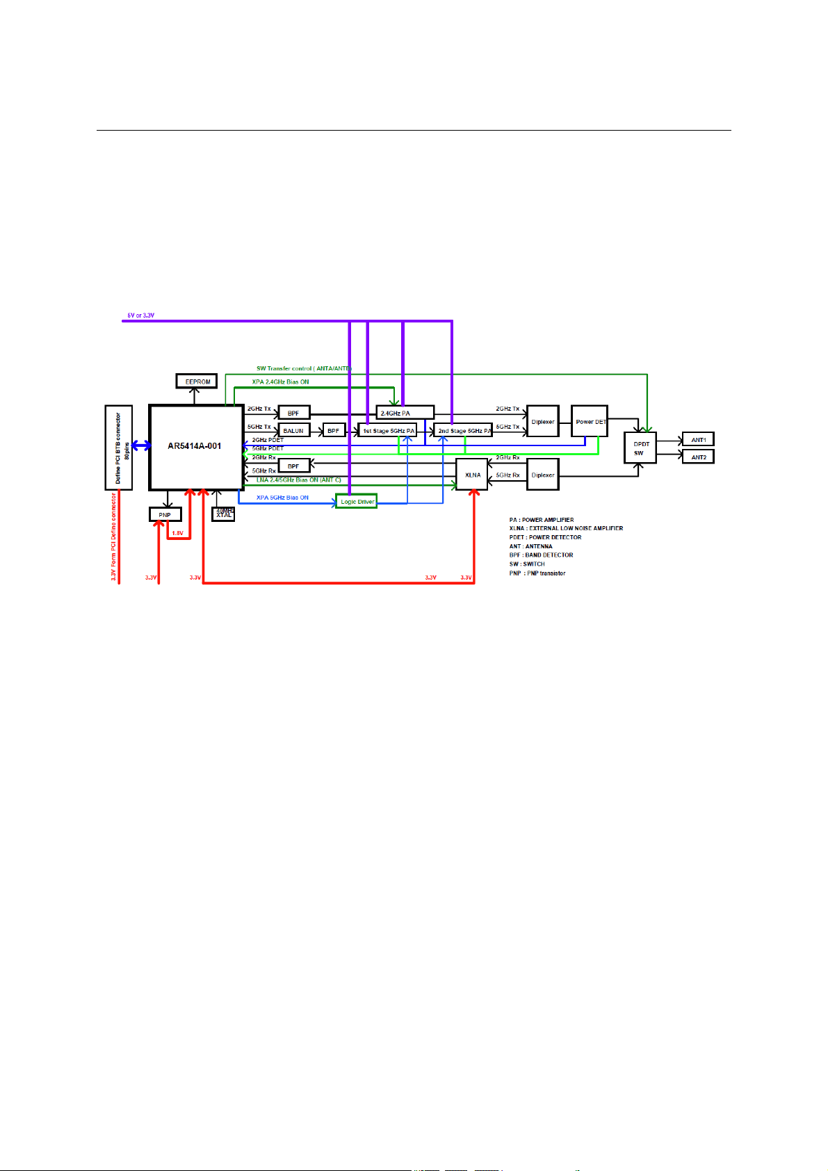
Block Diagram
Below is a block diagram of the WAPA004. Primary board components are in bold, while external connections
are italicized.
Page 10
WAPA004 User’s Manual Getting Started
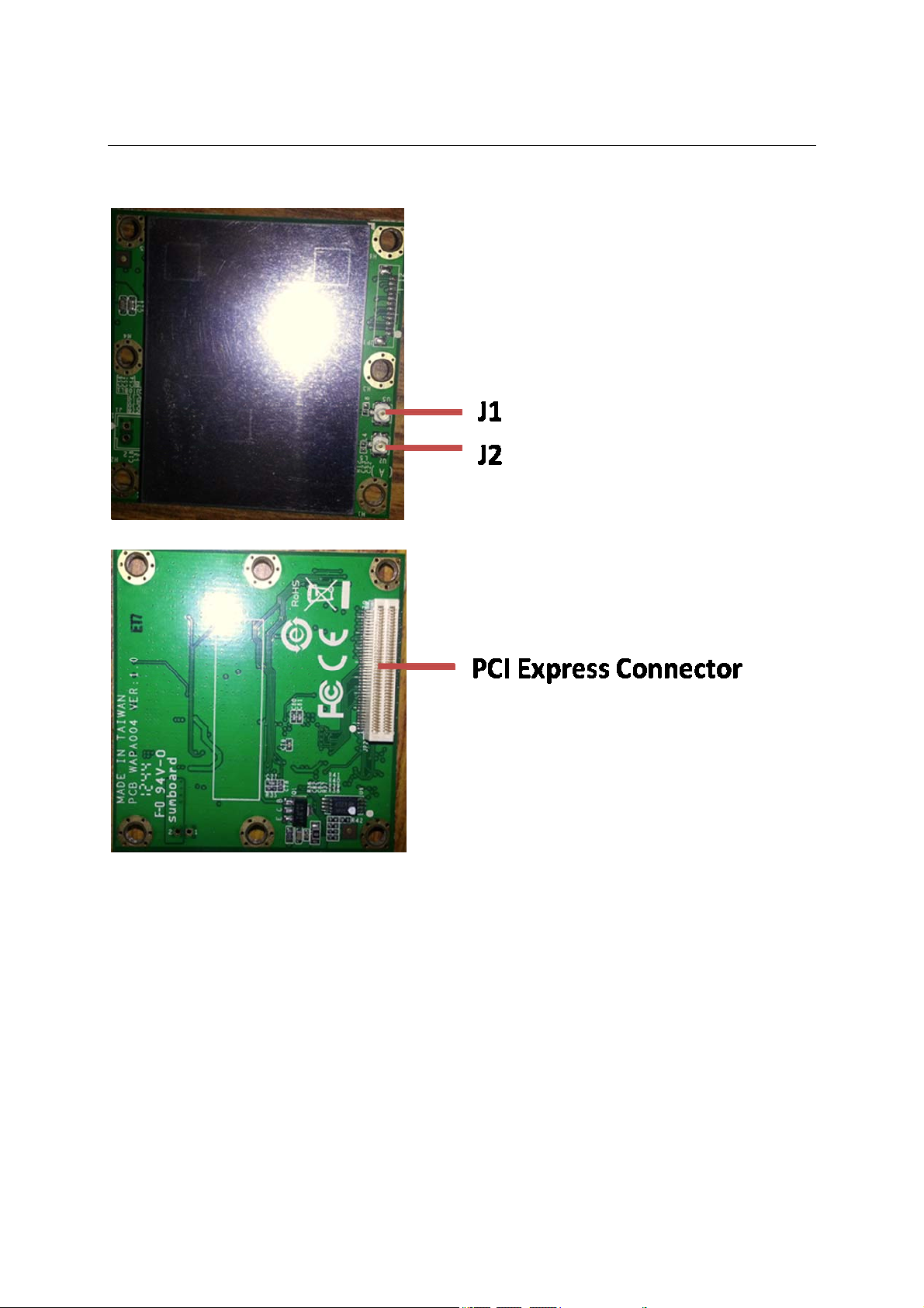
Connector Locations
Page 11

WAPA004 User’s Manual Getting Started
PCI Bus Connector PIN Assignments
Page 12

WAPA004 User’s Manual Getting Started
Hardware Installation
The WAPA004 can be installed into all Moxa wireless system board series.
Step for Installation
1. Attach the WLAN antenna to connector J1.
2. If using 2nd WLAN antenna, attach it to connector J2.
3. Install the WAPA004 PCI card on the system board. Apply pressure to both bus
connectors and gently press the board onto the stack. The board should slide into the matching
bus connectors. Do not attempt to force the board, as this can lead to bent/broken pins.
4. Screw on the WAPA004 PCI card.
5. If any power boards are to be stacked above the WAPA004, install them.
6. Screw on the all the necessary chassis.
Software Installation
After physically installing the WAPA004, your operating system must be configured to recognize
the new system board.
Step for Installation
1. Apply power to the system board.
2. Connect system board and PC with Ethernet cable.
3. Open a browser and type: 192.168.127.253 to open the system login webpage.
4. Login the webpage with default password: root in order to verify that all of the hardware is
install properly.
Page 13

WAPA004 User’s Manual Getting Started
Federal Communication Commission Interference
Statement
This equipment has been tested and found to comply with the limits for a Class B digital device, pursuant to Part
15 of the FCC Rules. These limits are designed to provide reasonable protection against harmful interference in a
residential installation. This equipment generates, uses and can radiate radio frequency energy and, if not
installed and used in accordance with the instructions, may cause harmful interference to radio communications.
However, there is no guarantee that interference will not occur in a particular installation. If this equipment does
cause harmful interference to radio or television reception, which can be determined by turning the equipment
off and on, the user is encouraged to try to correct the interference by one of the following measures:
- Reorient or relocate the receiving antenna.
- Increase the separation between the equipment and receiver.
- Connect the equipment into an outlet on a circuit different from that to which the receiver is connected.
- Consult the dealer or an experienced radio/TV technician for help.
FCC Caution:
To assure continued compliance, (example - use only shielded interface cables when connecting to computer or
peripheral devices) any changes or modifications not expressly approved by the party responsible for compliance
could void the user's authority to operate this equipment.
This device complies with Part 15 of the FCC Rules. Operation is subject to the following two conditions:
(1) This device may not cause harmful interference, and
(2) This device must accept any interference received, including interference that may cause undesired operation.
IMPORTANT NOTE:
This module is restricted to mobile configuration. To comply with FCC RF exposure compliance requirements,
the antenna used for this transmitter must be installed to provide a separation distance of at least 20 cm from all
persons and must not be co-located or operating in conjunction with any other antenna or transmitter. This
transmitter module must not be co-located or operating in conjunction with any other antenna or transmitter
CAUTION:
Any changes or modifications not expressly approved by the grantee of this device could void the user's
authority to operate the equipment.
End Product Labeling
This transmitter module is authorized only for use in device where the antenna may be installed such that 20cm
may be maintained between the antenna and users. The final end product must be labeled in a visible area with
the following: "Contains FCC ID: SLE-WAPA004 ”
Page 14

WAPA004 User’s Manual Getting Started
RF exposure warning
This equipment must be installed and operated in accordance with provided
instructions
and the antenna(s) used for this transmitter must be installed to provide a separation
distance of at least 20 cm from all persons and must not be co-located or operating in
conjunction with any other antenna or transmitter. End-users and installers must be
provide with antenna installation instructions and transmitter operating conditions for
satisfying RF exposure compliance.
Information for the OEMs and Integrators
The following statement must be included with all versions of this document supplied to an
OEM or integrator, but should not be distributed to the end user.
1) This device is intended for OEM integrators only.
2) Please see the full Grant of Equipment document for other restrictions.
This radio transmitter FCCID: SLE-WAPA004 has been approved by FCC to operate with the
antenna types listed below with the maximum permissible gain and required antenna
impedance for
each antenna type indicated. Antenna types not included in this list, having a gain greater
than the
maximum gain indicated for that type, are strictly prohibited for use with this device.
ANTENNA LIST
No. Manufacturer
1
2
KINSUN ANT-WDB-0-2 BK (main)(aux)
KINSUN ANT-WDB-ANM-0502 (main)(aux)
Part No.
Peak Gain
2.9dBi in 2.4 GHz
2.3dBi in 5 GHz
4.62dBi in 2.4 GHz
1.41dBi in 5 GHz
Note:The antenna connector is Reverse SMA type (ANT-WDB-0-2 BK) and N type (ANT-WDB-ANM-0502)
Note:
This is a specific product that requires professional installation and configuration, must be
performed by trained technical engineers to install the antenna, the MOXA agents contact
information as follows:
Page 15

WAPA004 User’s Manual Getting Started
NCC 警語:
經型式認證合格之低功率射頻電機,非經許可,公司、商號或使用者均不得擅自變
更頻率、加大功率或變更原設計之特性及功能。
低功率射頻電機之使用不得影響飛航安全及干擾合法通信;經發現有干擾現象時,
應立即停用,並改善至無干擾時方得繼續使用。
前項合法通信,指依電信法規定作業之無線電通信。低功率射頻電機須忍受合法通
信或工業、科學及醫療用電波輻射性電機設備之干擾。
本模組於取得認證後將依規定於模組本體標示審驗合格標籤,並要求最終產品平台
廠商
(OEM Integrator)於最終產品平台(End Product)上標示” 本產品內含射頻模組,
其 NCC 型式認證號碼為: CCXXxxYYyyyZzW
在 5.25 ~ 5.35GHz 頻帶內操作之無線資訊傳輸設備,限於室內使用。
 Loading...