


NPort W2150A/W2250A Series
User’s Manual
Edition 10.1, September 2018
www.moxa.com/product
© 2018 Moxa Inc. All rights reserved.

NPort W2150A/W2250A Series
User’s Manual
The software described in this manual is furnishe d under a license agr eeme nt and may be used only in accordance
with the terms of that agreement.
Copyright Notice
© 2018 Moxa Inc. All rights reserved.
Trademarks
The MOXA logo is a registered trademark of Moxa Inc.
All other trademarks or registered marks in this manual belong to their respective manufacturer s .
Disclaimer
Information in this document is subject to change without no tic e and doe s no t repres e nt a co mmitment o n the part of
Moxa.
Moxa provides this document as is, witho ut warr anty of any kind, either expressed or implied, includ ing , but not
limited to, its particular purpos e . Moxa reserves the right to make improve ments and /or change s to this manual, or to
the products and/or the programs describ ed in this manual, at any time .
Information provided in this manual is intend e d to be accurate and reliable. However, Moxa assumes no resp o ns ibility
for its use, or for any infringements on the rights of third parties that may result from its use .
This product might include unintentional technical or typographical errors. Changes are periodically made to the
information herein to correc t such er rors, and these changes are incorporated into ne w editio ns of the publication.
Technical Support Contact Information
www.moxa.com/support
Moxa Americas
Toll-free: 1-888-669-2872
Tel: +1-714-528-6777
Fax: +1-714-528-6778
Moxa Europe
Tel: +49-89-3 70 03 99-0
Fax: +49-89-3 70 03 99-99
Moxa India
Tel: +91-80-4172-9088
Fax: +91-80-4132-10 45
Moxa China (Shanghai office)
Toll-free: 800-820-5036
Tel: +86-21-5258-9955
Fax: +86-21-5258-55 05
Moxa Asia-Pacific
Tel: +886-2-8919-1230
Fax: +886-2-8919-1231

Table of Contents
1. Introduction ...................................................................................................................................... 1-1
Overview ........................................................................................................................................... 1-2
Package Checklist ...............................................................................................................................1-2
Product Features ................................................................................................................................1-3
Serial Port Pin Assignments ..................................................................................................................1-3
2. Getting Started.................................................................................................................................. 2-1
Overview ........................................................................................................................................... 2-2
Panel Layout ...................................................................................................................................... 2-2
LED Indicators .................................................................................................................................... 2-3
Top Panel LED Indicators ..............................................................................................................2-3
End Panel LED Indicators ..............................................................................................................2-3
Pull High/Low Resistors for RS-422/485 ................................................................................................. 2-4
Placement Options ..............................................................................................................................2-5
Connecting the Hardware.....................................................................................................................2-5
Connecting to the Network ...........................................................................................................2-6
Connecting the Power ..................................................................................................................2-6
Connecting to a Serial Device .......................................................................................................2-6
3. Initial IP Configuration ..................................................................................................................... 3-1
Overview ........................................................................................................................................... 3-2
Factory Default IP Settings ..................................................................................................................3-2
Using ARP to Assign an IP Address ........................................................................................................3-2
Using the Telnet Console to an Assign IP Address ...................................................................................3-3
Using the Serial Console to an Assign IP Address ....................................................................................3-6
4. Introduction to Operation Modes ...................................................................................................... 4-1
Overview ........................................................................................................................................... 4-2
Real COM Mode .................................................................................................................................. 4-2
RFC2217 Mode ................................................................................................................................... 4-3
TCP Server Mode ................................................................................................................................4-3
TCP Client Mode ................................................................................................................................. 4-3
UDP Mode .......................................................................................................................................... 4-4
Pair Connection Modes ........................................................................................................................4-4
Ethernet Modem Mode .........................................................................................................................4-4
5. Installing and Configuring the Software ........................................................................................... 5-1
Overview ........................................................................................................................................... 5-2
Device Search Utility (DSU) .................................................................................................................5-2
Installing the DSU .......................................................................................................................5-2
Finding NPort Device Servers on a Network .................................................................................... 5-4
Modifying NPort IP Addresses ........................................................................................................5-5
Upgrading NPort Firmware ............................................................................................................5-6
NPort Windows Driver Manager ............................................................................................................5-7
Installing NPort Windows Driver Manager .......................................................................................5-7
Adding Mapped Serial Ports ........................................................................................................ 5-10
Configuring Mapped Serial Ports .................................................................................................. 5-13
Command-Line Installation/Removal ............................................................................................ 5-17
Linux Real TTY Drivers ...................................................................................................................... 5-19
Basic Steps ............................................................................................................................... 5-19
Installing Linux Real TTY Driver Files ........................................................................................... 5-19
Mapping TTY Ports ..................................................................................................................... 5-20
Removing Mapped TTY Ports ....................................................................................................... 5-20
Removing Linux Driver Files ........................................................................................................ 5-21
UNIX Fixed TTY Drivers ..................................................................................................................... 5-21
Installing the UNIX Driver........................................................................................................... 5-21
Configuring the UNIX Driver ....................................................................................................... 5-22
6. Web Console: Basic Settings ............................................................................................................. 6-1
Overview ........................................................................................................................................... 6-2
Basic Settings .................................................................................................................................... 6-4
7. Web Console: Network Settings ........................................................................................................ 7-1
Overview ........................................................................................................................................... 7-2
Network Settings ................................................................................................................................7-2
General Settings .........................................................................................................................7-2
Ethernet/Bridge Settings ..............................................................................................................7-3
WLAN Settings ............................................................................................................................7-6
Advanced Settings ..................................................................................................................... 7-24
8. Web Console: Serial Port Settings ..................................................................................................... 8-1
Overview ........................................................................................................................................... 8-2

Serial Port Settings ......................................................................................................................8-2
Communication Parameters ........................................................................................................ 8-21
Data Buffering/Log .................................................................................................................... 8-22
9. Web Console: System Management ................................................................................................... 9-1
Overview ........................................................................................................................................... 9-2
System Management ...........................................................................................................................9-2
Misc. Network Settings .................................................................................................................9-2
Auto Warning Settings .................................................................................................................9-6
Maintenance ............................................................................................................................. 9-10
Certificate ................................................................................................................................ 9-14
10. Web Console: System Monitoring .................................................................................................... 10-1
Overview ......................................................................................................................................... 10-2
System Monitoring ............................................................................................................................ 10-2
Serial Status ............................................................................................................................. 10-2
System Status .......................................................................................................................... 10-4
11. Web Console: Restart ...................................................................................................................... 11-1
Overview ......................................................................................................................................... 11-2
Restart ............................................................................................................................................ 11-2
Restart System ......................................................................................................................... 11-2
Restart Ports............................................................................................................................. 11-3
12. Android API Instructions ................................................................................................................ 12-1
Overview ......................................................................................................................................... 12-2
How to Start MxNPortAPI ........................................................................................................... 12-2
MxNPortAPI Function Groups .............................................................................................................. 12-3
Example Program ............................................................................................................................. 12-3
A. SNMP Agents with MIB II & RS-232-Like Groups .............................................................................. A-1
RFC1213 MIB-II Supported SNMP Variables ...........................................................................................A-1
System MIB ................................................................................................................................A-1
Interfaces MIB ............................................................................................................................A-1
IP MIB .......................................................................................................................................A-1
ICMP MIB ...................................................................................................................................A-2
UDP MIB ....................................................................................................................................A-2
Address Translation .....................................................................................................................A-2
TCP MIB .....................................................................................................................................A-2
SNMP MIB ..................................................................................................................................A-2
RFC1317: RS-232 MIB Objects .............................................................................................................A-3
Generic RS-232-like Group ...........................................................................................................A-3
RS-232-like General Port Table .....................................................................................................A-3
RS-232-like Asynchronous Port Group ............................................................................................A-3
The Input Signal Table .................................................................................................................A-3
The Output Signal Table ...............................................................................................................A-3
B. Well-Known Port Numbers ................................................................................................................ B-1
C. Ethernet Modem Commands .............................................................................................................. C-1
Dial-in Operation ................................................................................................................................C-1
Dial-out .............................................................................................................................................C-1
Disconnection Request from Local S ite ..................................................................................................C-1
Disconnection Request from Remote Site ...............................................................................................C-1
AT Commands ....................................................................................................................................C-2
S Registers ........................................................................................................................................C-3
D. Federal Communication Commission Interference Statement ........................................................... D-1
E. FCC Warning Statement .................................................................................................................... E-1

The following topics are covered in this chapte r:
Overview
Package Checklist
Product Features
Serial Port Pin Assignments
1
1. Introduction

NPort W2150A/W2250A Seri es Introduction
Overview
In this chapter, we introduce the basic features and specifications of the NPort W2150A/W2250A and NPort
W2150A/W2250A-T, ref er red to collectively as the NPort W2150A/W2250A Series.
The NPort W2150A/W2250A Series of wireless device servers are used to connect RS-232/422/485 serial
devices or Ethernet devices, including PLCs , meters , and sensors, to a wireless LAN. Your communications
software will be able to access the serial devices or Ethernet devices from anywhere over a local LAN,
WLAN, or the Internet. Moreover , the WLAN enviro nme nt offers an excellent solution for applicatio ns in
which the serial devices and Ethernet devices are move d freq ue ntly from place to place.
The NPort W2150A/W2250A supports both automatic IP configuration proto cols (D HC P, BOOT P) and manual
configuration using a standard web browser. Both IP configuration methods ensure quick and ef fe c tive
installation. In addition, a utility ca lle d “N Por t Windows Dr iver Manager” makes port mapping easy.
The external antenna can be adjusted for maximum signal streng th. You can also choose to use your own
antenna for additional flexibility and scalability. A signal strength indic a to r on the front panel makes it easier
for you to troubleshoot any connectio n problems.
The NPort W2150A/W2250A Series offers different operation modes to ensure co mpa tibility with standard
network APIs, including TCP Server Mode , TCP Clie nt Mode, and UDP Mode. Real COM/TTY drivers are
provided to allow legacy ser ial-bas e d sof tware to communicate over an IP network instantly. This preserves
your software investment w hile providing all the advantages of ne twor king your serial devices.
For easier management, the NPort W2150A/W2250A inc ludes features such as password authentication, IP
filtering, 64-bit and 128 -bit WEP encryption, and SNMP support.
Package Checklist
Standard Accessories
• 1 NPort W2150A or NPort W2250A wireless device server
• 1 antenna 2.4/5 GHz: ANT-WDB-ARM-02
• 100 to 240 VAC power adapter (excluding T models)*
• 1 Ethernet cable: CBL-RJ458P-100
• Quick installation guide (printed)
•Warranty card
NOTE The package includes one power adapter suitable for your region.
Optional Accessories
• DK35A: DIN-rail mounting kit (35 mm)
• Power-jack-to-terminal-block po we r c able (P/N : 9199000000900)
NOTE Please notify your sales representative if any of the above items is missing or damaged.
1-2

NPort W2150A/W2250A Seri es Introduction
Product Features
• Supports wireless client: links any serial or Ethernet device to an IEEE 802.11a/b/g/n network
• Web-based configuration over Ethernet or WLAN
• Enhanced remote configuration with HTTPS, SSH
• Secure data access with WEP, WPA, WPA2
• Built-in WLAN site survey tool
• Fast Roaming for quick automatic switching between access points
• Per-port offline port buffering and serial data log
• Dual power inputs via power jack and terminal block
Serial Port Pin Assignments
Pin RS-232 RS-422/ RS-485 (4W) RS-485 (2W)
1 DCD TxD-(A) –
2 RXD TxD+(B) –
3 TXD RxD+(B) Data+(B)
4 DTR RxD-(A) Data-(A)
5 GND GND GND
6 DSR – –
7 RTS – –
8 CTS – –
9 – – –
1-3

The following topics are covered in this chapte r:
Overview
Panel Layout
LED Indicators
¾ To p Panel LED Indicators
¾ End Panel LED Indicators
Pull High/Low Resistors for RS-422/485
Placement Options
Connecting the Hardware
¾ C o nne c ting to the Network
¾ C onnecting the Power
¾ C onnecting to a Serial Device
2
2. Getting Started
NPort W2150A/W2250A Seri e s Getting Started
Overview
This chapter presents the hardware features of the NPort W2150/W2250A Series and explains how to
connect the hardware.
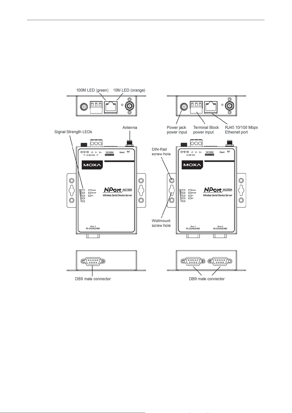
Panel Layout
NPort W2150A/W2150A-T NPort W2250A/W2250A-T
2-2

NPort W2150A/W2250A Seri e s Getting Started
LED Indicators
Top Panel LED Indicators
Name Color Function
Steady on: Power is on, and the NPort is booting up.
Ready
WLAN
Serial 1
Serial 2
Signal Strength
(5 LEDS)
Red
Green
Off Power is off, or a power error condition exis ts .
Green
Off Wireless not enabled.
Orange Serial port is receiving data.
Green Serial port is transmitting data.
Off No data is flowing to or from the serial port.
Red
Green
Blinking: An I P co nf lic t ex is ts , or the DHCP/ B OOT P serv er did not
respond pr operly.
Steady on: The NPor t is functioning normally.
Blinking: The unit is re s po nd ing to Loc ate f unc tion.
Steady on: Wireless enabled
Blinking: The NPor t c a n’t establish WLAN connection with AP
(Infrastructure) or station (Ad-Hoc)
1 Red - the signal strength (RSSI) is worse than -88 dBm
2 Red - the signal strength (RSSI) is between -87 to -79 dBm
3 Green - the signal strength (RSSI ) is betw e e n -78 to -68 dB m
4 Green - the signal strength (RSSI ) is betw e e n -67 to -60 dB m
5 Green - the signal strength (RSSI ) is betw e e n -59 to -45 dB m
End Panel LED Indicators
Name Color Function
10 Mbps Ethernet connection
100 Mbps Ethernet connection
Ethernet
Orange
Green
Off Ethernet cable is disconnected
2-3
NPort W2150A/W2250A Seri e s Getting Started
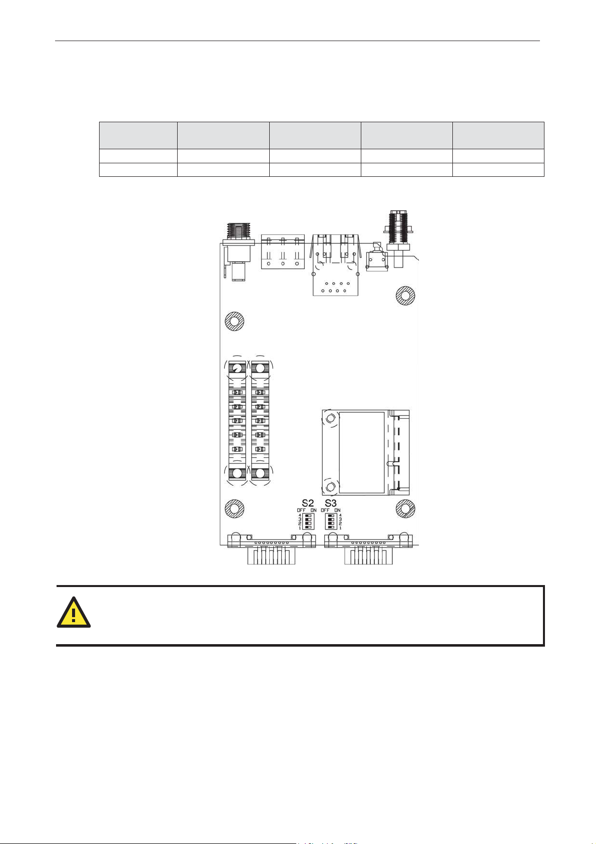
Pull High/Low Resistors for RS-422/485
You may need to set the pull high/low resistor s when ter m ination r esistors are used for certain RS-422 or
RS-485 environments.
S2 (Serial 1)
S3 (Serial 2)
ON .ƻ .ƻ ƻ –
OFF .ƻ .ƻ *N/A –
*Default
S3 is for NPort W2250A only
Pull high resistor
DIP 1
DIP 2
Pull low resistor
DIP 3
Terminal resistor
DIP 4
Reserved
ATTENTION
'RQRWXVHWKH.ƻVHWWLQJZKLOHLQ56-232 mode. Doing so will degrade the RS-232 signals and re d uce the
effective communication distance.
2-4
NPort W2150A/W2250A Seri e s Getting Started
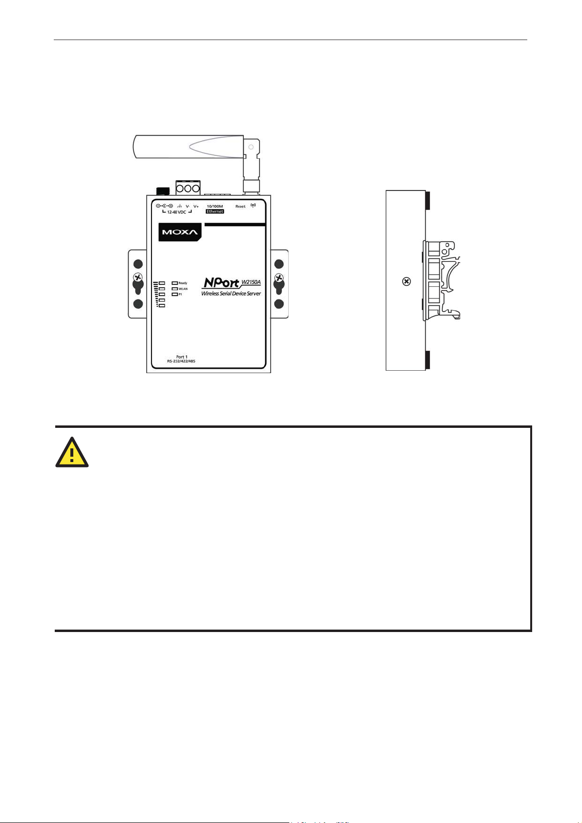
Placement Options
The NPort can be placed on a desktop or other horizontal surface. You can also install the NPort on a DINrail or on the wall.
Wall Mounting DIN-Rail Mounting
Connecting the Hardware
ATTENTION
Before connecting the hardware, follow these important wiring safety precautio ns :
Disconnect power source
Do not install or wire this unit or any attached device s with the pow er connected. Disconnect the power
before installation by removing the power cor d bef or e installing and/or wiring your unit.
Follow maximum curre nt ratings
Calculate the maxim um pos sible current in each power wire and common wir e . Observe all electrical codes
dictating the maximum current allowable for each wire size.
If the current goes above the maximum ratings, the wiring could overheat, causing serious damage to your
equipment.
Use caution - unit may get hot
The unit will generate heat during operation, and the casing may be too hot to touch. Take care when
handling the unit. Be sure to leave adequate space for ventilatio n.
The following guidelines will help e ns ure tr o uble -f re e sig n al communic ation with the NPort.
• Use separate paths to route wiring for power and devices to avoid interfer ence. Do not run signal or
communication wiring and power wiring in the same wire conduit. The r ule of thumb is that wir ing that
shares similar electrical characteristics can be bundled toge t h er.
• If power wiring and device wiring paths must cross, make sure the wires are perpendicular at the
intersection point.
• Keep input wiring and output wiring separate.
• Label all wiring to each device in the system for easier testing and troubleshooting
2-5

NPort W2150A/W2250A Seri e s Getting Started
Connecting to the Network
Use the supplied Ethernet cable to connect the NPort to your Ethernet network. If the cable is properly
connected, the NPort will indicate a valid conne ction to the Ethernet as follows:
• A green Ethernet LED indicates a valid connection to a 100 Mbps Etherne t ne twork .
• An orange Ethernet LED indicates a valid connectio n to a 10 Mbps Ether ne t ne twor k .
• A flashing Ethernet LED indicates that Ethernet packets are being trans mitte d or re c e ive d .
Connecting the Power
Connect the VDC power line (12 to 48 V) to the NPort’s power jack or terminal block (recommended for only
one connection at a time). If power is proper ly conne c t e d , the “R e a dy ” LED w ill initially glow red. When the
system is ready, the “Ready” LED will turn green.
Connecting to a Serial Device
Use a serial cable to connect your serial device to a serial port on the NPort.
2-6

3. Initial IP Configuration
The following topics are covered in this chapte r:
Overview
Factory Default IP Settings
Using ARP to Assign an IP Address
Using the Telnet Console to an Assign IP Address
Using the Serial Console to an Assign IP Address
3
NPort W2150A/W2250A Seri e s Initial IP Configuration
Overview
This chapter presents sev er a l way s to a s s ign the NPort’s IP address for the firs t time . Ple ase re fe r to
Chapter 2 for instructions on connec ting to the network.
The web console is the recommended method for configuring the NPort. Please refer to Chapter 5 and 6 for
details on using the web console for configuratio n.
ATTENTION
The LAN and WLAN interfaces cannot be used at the same time if you don't enable the Ethernet Bridge
mode (please refer to Chapter 7 for mor e details ). If the Ethernet link is active, then WLAN connectio ns will
be disabled. If the WLAN connection is active, then the Ethernet link will be disabled.
ATTENTION
Make sure that the Ethernet cable is connected befor e pow er ing up the NPor t.
Factory Default IP Settings
Network Interfac e IP Configuration IP Address Netmask
LAN Static 192.168.126.254 255.255.255.0
WLAN Static 192.168.127.254 255.255.255.0
If your NPort is configured to obtain its IP settings from a DHCP or BOOTP server but is unable to get a
response, it will use the factory de fault IP address and netmask.
ATTENTION
If you forget the IP address of yo ur NPort, you can look it up using the Device Se arc h U tility (DSU). After
the Device Search Utility (DSU ) has fo und all NPorts on the network, each unit will be listed with its I P
address. Please refer to Ch apte r 11 for additional information on using the Dev ic e S e arc h Utility (DSU).
Using ARP to Assign an IP Address
The ARP (Address Resolution Protocol) command can be used to assign an IP address to the NPort. The ARP
command tells your computer to associate the NPort’s MAC address with the specified IP address. You must
then use Telnet to access the NPort, at which point the device server’s IP address will be re co nfigured. This
method only works when the NPort is configured with default I P setting s .
1. Select a valid IP address for your NPor t. Co nsult with your network administrator if ne ces sar y .
2. Obtain the NPort’s MAC address from the label on its bottom panel.
3. From the DO S prompt, execute the arp -s command with the desired IP address and the NPort’s MAC
address, as in the following example:
arp -s 192.168.200.100 00-90-E8-xx-xx-xx
In this example, 192.168.200.100 is the new IP address that will be assigned to the NPort, and 00-90E8-xx-xx-xx is the NPor t’ s MAC addr ess .
4. From the DOS prompt, execute a special Te lne t co mmand using po rt 6000, as in the following example:
telnet 192.168.200.100 6000
In this example, 192.168.200.100 is the new IP address that will be assigned to the NPort.
3-2
NPort W2150A/W2250A Seri e s Initial IP Configuration
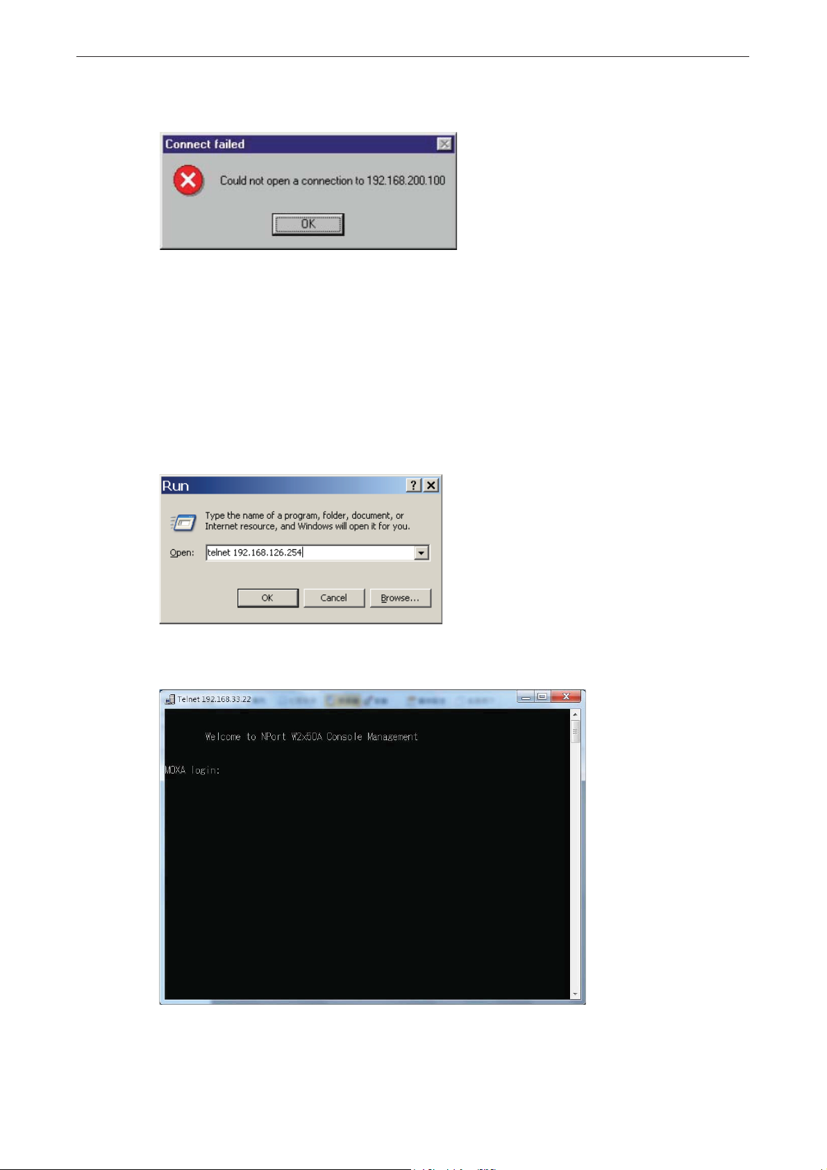
5. You will see a message indicating that the connection failed.
The NPort will automatically reboot with the new IP addre s s. You c a n ver ify that the c o nfigur atio n was
successful by connecting to the new IP address with Telnet, ping, the web console, or the Device Search
Utility (DSU).
Using the Telnet Console to an Assign IP
Address
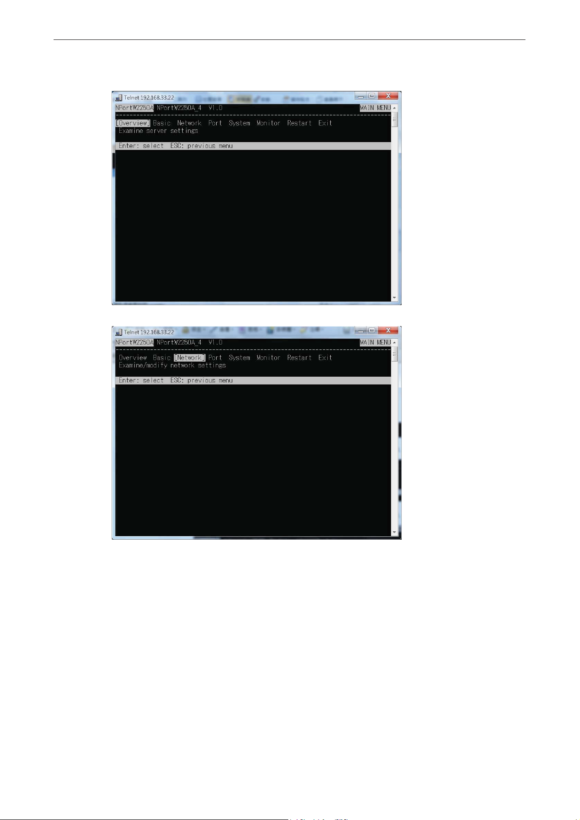
1. Select Run… from the Windows Start menu.
2. Enter telnet 192.168.126.254 (the NPort’s default IP address ) and c lick [OK].
3. Enter your login account and password, then press ENTER.
(Default login is admin and password is moxa.)
3-3
NPort W2150A/W2250A Seri e s Initial IP Configuration
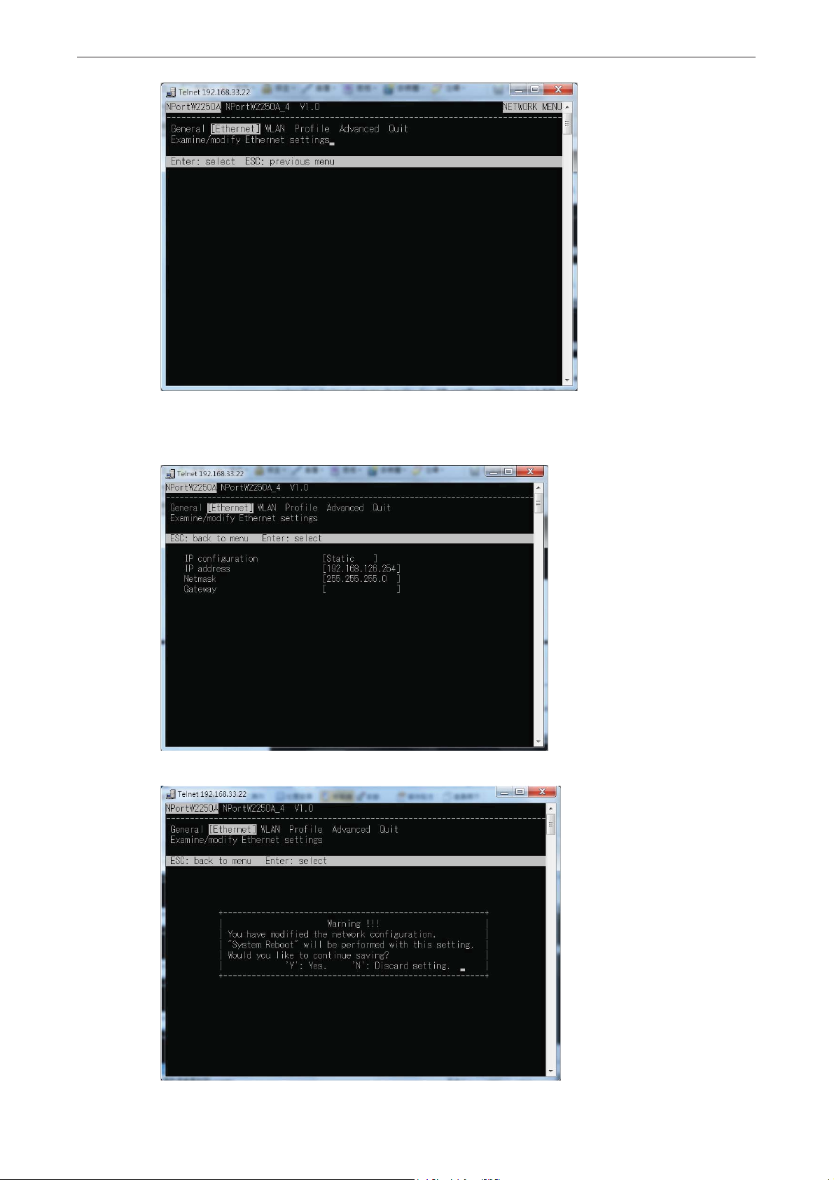
4. You will login to the Overview page.
5. Press N or use the cursor keys to select Network and press ENTER.
6. Press E or use the cursor keys to select Ethernet and press ENTER.
3-4
NPort W2150A/W2250A Seri e s Initial IP Configuration
7. Use the cursor keys to navigate between the different fields. For IP address, Netmask, and Gateway,
enter the desired values directly. For IP configuration and LAN speed, press ENTER to open a
submenu and select between the available options.
8. Press ESC to return to the menu. When prompted, press Y to save the configuration changes.
3-5

NPort W2150A/W2250A Seri e s Initial IP Configuration
The NPort will reboot with the new IP settings. You can telnet to the new IP to login again.
Using the Serial Console to an Assign IP
Address
Before using the NPort’s serial c o nso le , turn off the power and use a serial cable to connect the NPort
console port to your computer’s s er ial port. Port 1 on the NPort serves as the console port. Use Port 1
connecting to the console port with a serial-based terminal or terminal emulator program, such as Windows
HyperTerminal. You may also download PComm Lite at www.moxa.com
ANSI or VT100, and the serial communication parameters should be set as 19200, 8, N, 1 (19200 fo r b a ud
rate, 8 for data bits, None for parity, and 1 for stop b its). As soo n as the co nne c tio n is open, you will b e
presented with a text menu display ing the NPor t W2150A/W2250A Series general setting s . Ple ase refer to
Chapter 4 for a description of the available setting s . The following instructions, we recommend us ing
PComm Terminal Emulator, which can be downloaded free of charge from
configuration procedure.
1. Connect your PC’s serial port to the NPort’s co nsole por t.
2. Open your terminal emulator program, suc h as Windows HyperTer minal. We r eco mmend using PComm
Terminal Emulator, which can be downloaded for free at www.moxa.com
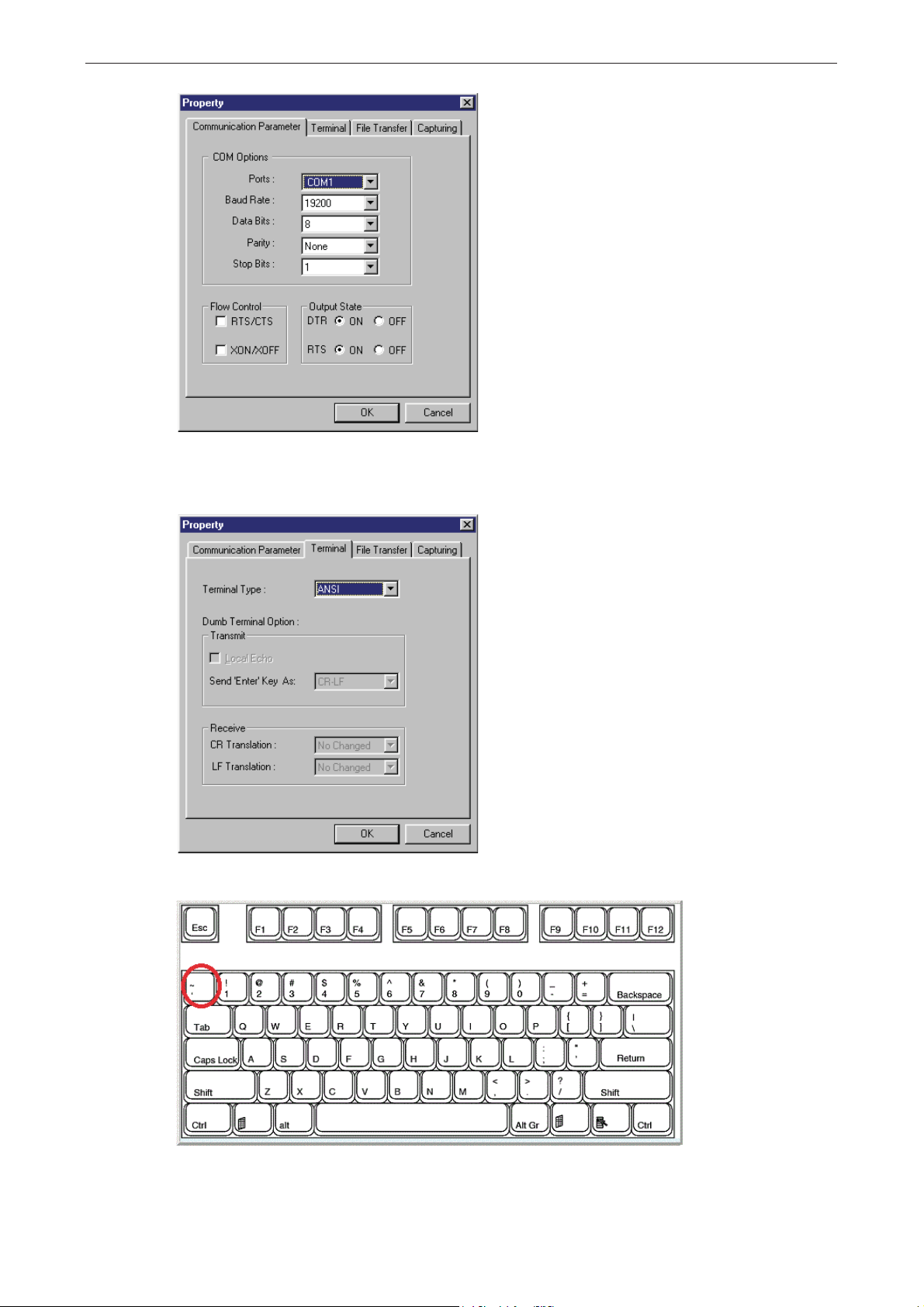
3. In your terminal emulator program, config ure the communication parameters for the serial port on the
PC. The parameters should be set to 19200 for baud rate, 8 for data bits, None for parity, an d 1 for
stop bits.
. The terminal type should be set as
www.moxa.com, to carry out the
.
3-6
NPort W2150A/W2250A Seri e s Initial IP Configuration
4. In your terminal emulator progr am, set the te r m inal typ e to ANSI or VT100. If you select Dumb
Terminal as the terminal type, some of the console functions—especially the “Monitor” functio n— m ay
not work properly.
5. Hold the grave accent key (`) down and power up the NPort.
The continuous string of grave accent characters triggers the NPort to switch from data mode to console
mode.
3-7

NPort W2150A/W2250A Seri e s Initial IP Configuration
6. The serial console will open and will be functionally identical to the Telnet console. Please refer to the
Telnet console section for instruc tio ns on how to naviga te the co nso le and co nfig ure the IP settings.
3-8

4. Introduction to Operation Modes
The following topics are covered in this chapter:
Overview
Real COM Mode
RFC2217 Mode
TCP Server Mode
TCP Client Mode
UDP Mode
Pair Connection Modes
Ethernet Modem Mode
4
NPort W2150A/W2250A Series Introduction to Operation Modes
Overview
This chapter introduces the different serial port operation modes that are available on the NPort
W2150A/W2250A Series . Each se rial port on the NPort is configured independ ently of the other ports, with
its own serial communication parameters and oper ation mode. The serial port’s operation mode determines
how it interacts with the network, and different modes are available to encompass a wide variety of
applications and devices.
Real COM and RFC2217 modes allow serial-based software to access the NPort serial port as if it were a
local serial port on a PC. These modes are appropriate when your application relies on Windows or Linux
software that was originally designed for locally attached COM or TTY devices. With these modes, you can
access your devices from the network using your existing COM/TTY-based software, without investing in
additional software.
Three different socket modes are available for user-d ev eloped socket programs: TCP Serve r , TCP Client,
and UDP Server/Client. For TCP applications, the appropriate mode depends on whether the connection
will be hosted or initiated from the NPort serial port or from the network. The main difference between the
TCP and UDP protocols is that TCP guarantee s delivery of data by requiring the recip ie n t to se nd an
acknowledgement to the sende r . UD P does not re q uire this typ e of ver ification, making it possible to offer
speedier delivery. UDP also allows multicasting of data to gro u p s of IP addresses and would be suitab le for
streaming media or noncritical messaging applic atio ns such as LED messag e board s .
Pair Connection Slave and Master modes are designed for serial-to-serial communication over Ethernet,
in order to overcome traditional limitations w ith se rial transmission distance.
In Ethernet Modem mode, the NPort acts as an Ethernet modem, providing a network connection to a host
through the serial port.
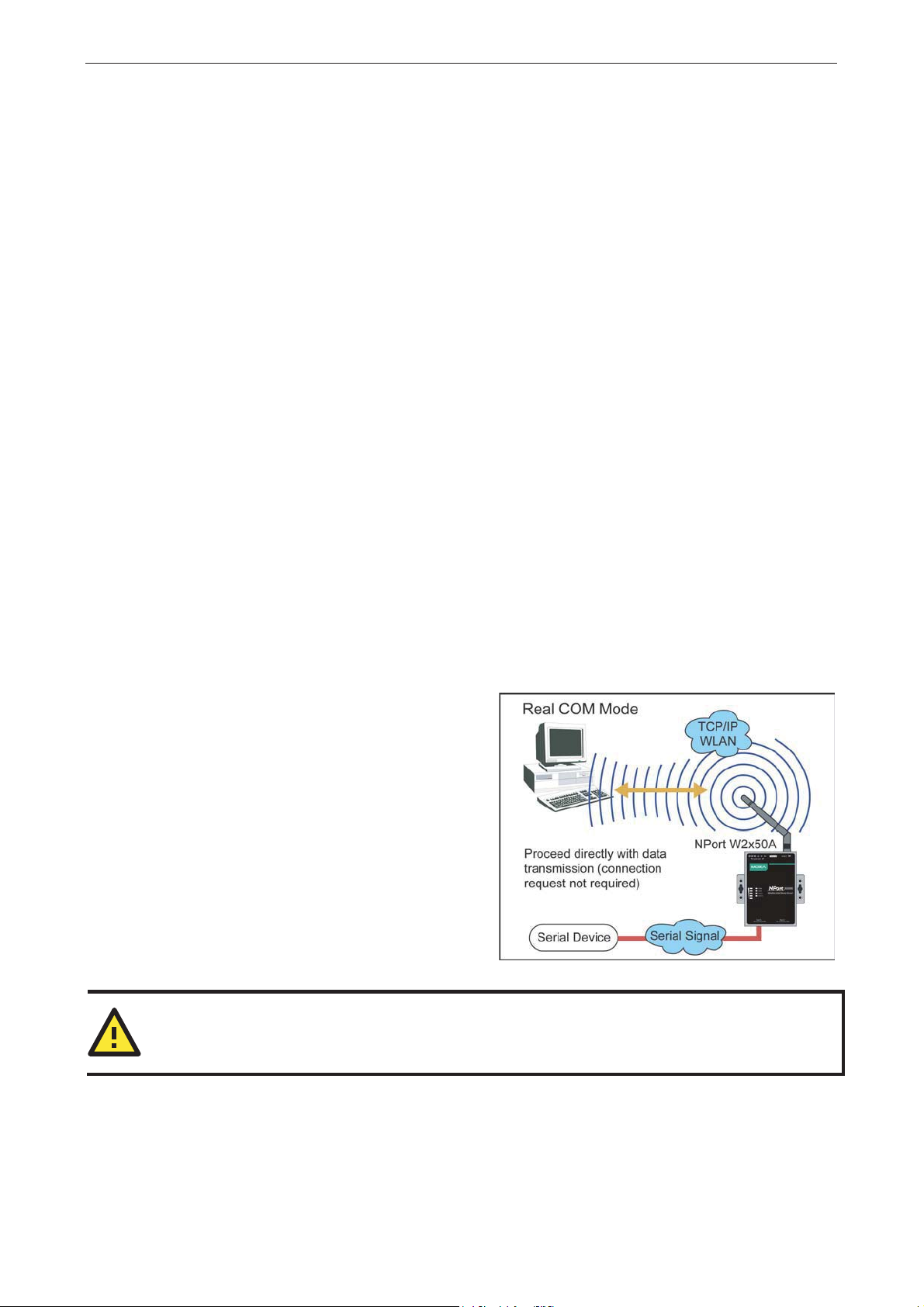
Real COM Mode
Real COM mode is designed to work with NPort
drivers that are installed on a network host. COM
drivers are provided for Windows systems, and TTY
drivers are provided for Linux and UNI X sys te m s .
The driver establishes a transparent connec tion to
the attached serial device by mapping a local serial
port to the NPort serial port. Real COM mode
supports up to four simultaneous connectio ns , so
multiple hosts can collect data from the attached
device at the same time.
ATTENTION
Real COM drivers are installed and config ur ed thro ugh NPort Windows Driver Manager.
Real COM mode allows you to continue using your ser ial communicatio ns s of tw a re to access devic e s that ar e
now attached to your NPort device server. On the host, the NPort Real COM driver automatically intercepts
data sent to the COM port, packs it into a TCP/IP packet, and redirec ts it to the network . At the other e nd of
the connection, the NPort device server acce pts the Ethernet frame, unpacks the TCP/IP packet, and sends
the serial data to the appropr iate dev ice.
4-2
NPort W2150A/W2250A Series Introduction to Operation Modes
ATTENTION
In Real COM mode, several hosts can have simultaneous access control over the NPort serial port. If
necessary, you can limit access by using the NPort’s Accessible IP settings. Please refer to Chapter 8 for
additional information on Accessible IP settings.
RFC2217 Mode
RFC-2217 mode is similar to Real COM mode, s ince it re lie s o n a drive r to trans p ar e ntly map a virtual COM
port on a host computer to a serial port on the NPort. The RFC2217 standard defines general COM port
control options based on the Telnet protocol and supports one connection at a time. Third party drivers
supporting RFC-2217 are widely available on the Internet and can be used to implement virtual COM
mapping.
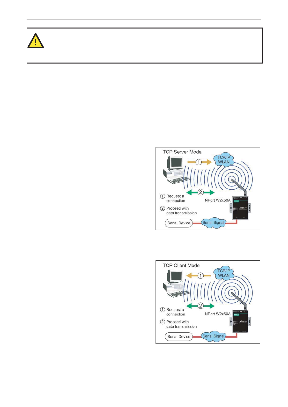
TCP Server Mode
In TCP Server mode, the NPort serial port is
assigned an IP:port address that is unique on your
TCP/IP network. It waits for the host compute r to
establish a connection to the attached serial device.
This operation mode also supports up to e ight
simultaneous connections, so multiple hos ts can
collect data from the attached device at the same
time.
Data transmission proceeds as follows:
A host requests a connection to the NPort serial
port.
Once the connection is established, data can be
transmitted in both direct io ns—from the host to the
device, and from the device to the host.
TCP Client Mode
In TCP Client mode, the NPort actively establishe s a
TCP connection to a specific network host when data
is received from the attache d se r ia l device. After the
data has been transferred, the NPort can
automatically disconnect from the host computer
through the Inactivity time settings. Pleas e re fe r to
Chapter 7 for details on these parameters .
Data transmission proceeds as follows:
The NPort requests a connection from the hos t.
The connection is established and data can be
transmitted in both direct io ns betw e e n the host and
device.
4-3
NPort W2150A/W2250A Series Introduction to Operation Modes
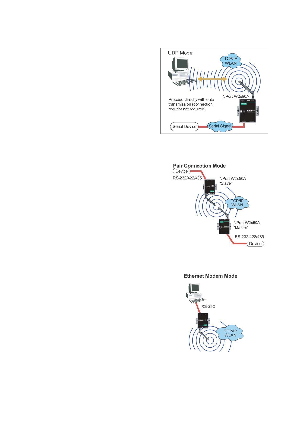
UDP Mode
UDP is similar to TCP but is faster and more
efficient. Data can be broadcast to or received from
multiple network hosts. However , UDP does no t
support verification of da ta and would no t be
suitable for applications wh ere d ata integ rity is
critical. It is ideal for message dis p lay app lic ations.
Pair Connection Modes
Pair Connection Master and Slave modes connect two
NPort device se rvers over a network for serial-toserial communication. A device attached to one NPort
can then communicate transparently to a device
attached to the other NPort, as if the two devices
were connected by a serial cable. Both data and
modem control signals are exchanged, except for
DCD signals. This can be used to overcome
traditional limitations with serial communic ation
distance and introduces many new possibilities for
serial-based device control.
Ethernet Modem Mode
Ethernet Modem mode is designed for use with legacy
operating systems, such as MS-DOS, that do not
support TCP/IP Ethernet. By connecting the pro perly
configured NPort serial port to the MS -DO S
computer’s serial port, it is possible to use legacy
software to transmit data over the Ether ne t when the
software was originally designed to transmit data over
a modem.
4-4

NPort W2150A/W2250A Series Introduction to Operation Modes
4-5

5
5. Installing and Configuring the Software
The following topics are covered in this chapter:
Overview
Device Search Utility (DSU)
¾ Installing the DSU
¾ Finding NPort Device Servers on a Network
¾ Modifying NPort IP Addresses
¾ Upgrading NPort Firmware
NPort Windows Driver Manager
¾ Installing NPort Windows Driver Manage r
¾ Adding Mapped Se rial Ports
¾ C onfiguring Mapped Serial Ports
¾ Command-Line Installation/Removal
Linux Real TTY Drivers
¾ Basic Steps
¾ Installing Linux Real TTY Driver Files
¾ Map p ing TTY Ports
¾ R e moving Mapped TTY Ports
¾ Removing Linux Driver Files
UNIX Fixed TTY Drivers
¾ I nstalling the UNIX Driver
¾ C onfiguring the UNIX Driver
NPort W2150A/W2250A Se ri e s Installing and Configuring the Software
Overview
This chapter describes how to install and use the NPor t Windo ws Driver Manager, the Device Search Utility
(DSU), and NPort Linux and UNIX drivers. You may downlo ad the s e items fr o m Moxa ’ s webs ite that is
provided with the NPort W2150A/W2250A Series.
NPort Windows Driver Manager is a utility that installs and manages NPort COM drivers for COM
mapping. The Device Search Utility (DSU) is a utility for the management of NPort device servers over
the network. You may also use the Device Search Utility (DS U ) to up grade the firmware.
Device Search Utility (DSU)
Installing the DSU
1. Download the DSU from Moxa’s website:
https://www.moxa.com/support/download.aspx?type=support&id=10137
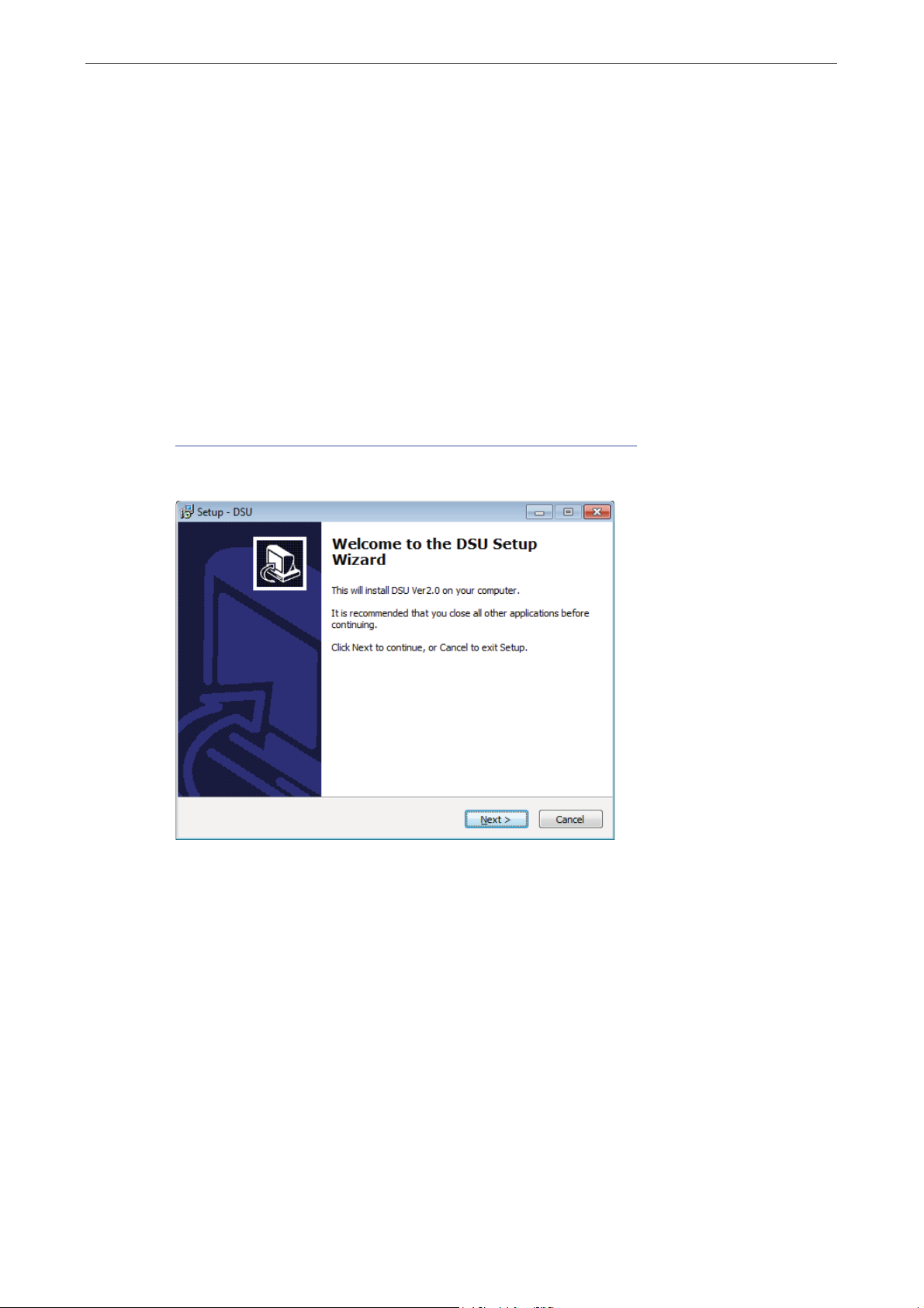
You may double click on the executable file. Once the program starts running , c lic k Yes to proceed.
2. The installation wizard will open. Click Next to proceed.
5-2
NPort W2150A/W2250A Se ri e s Installing and Configuring the Software
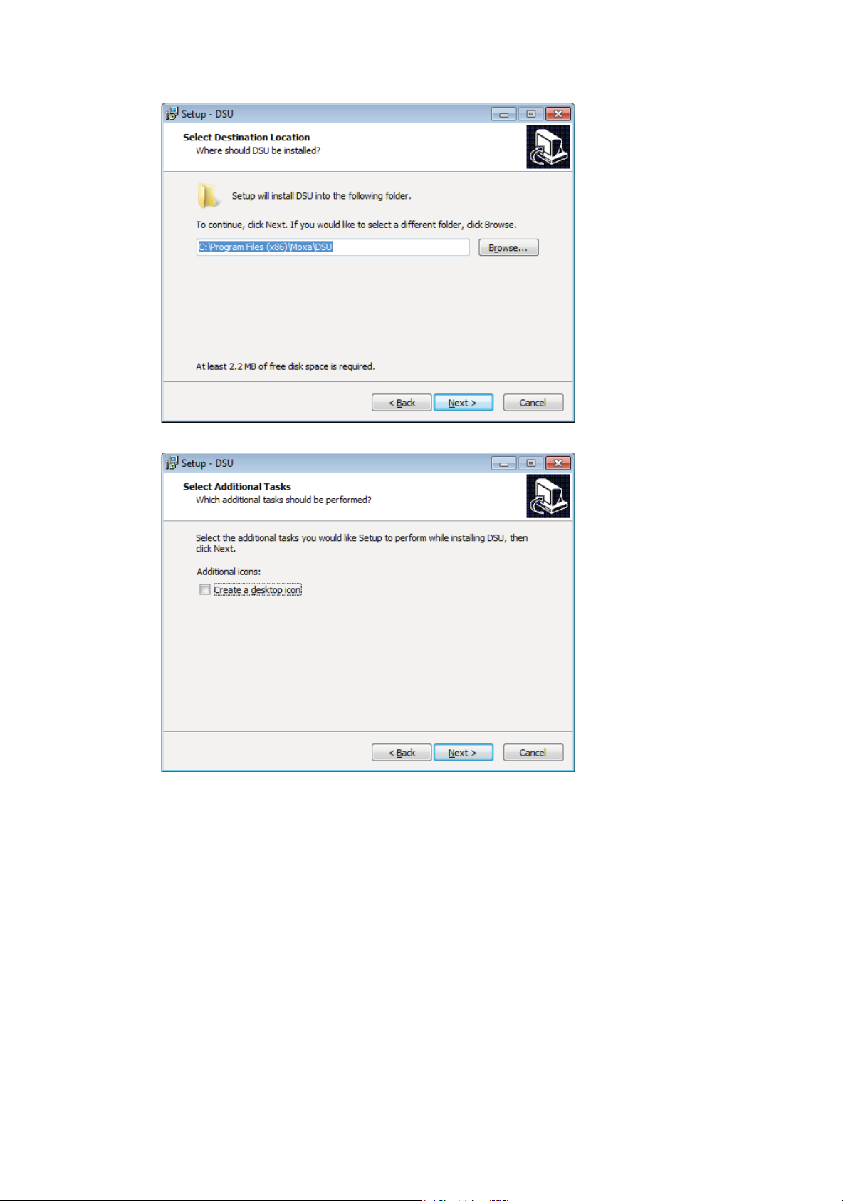
3. Select a destination location and click Next to proceed.
4. Indicate if you wish to create a desktop icon and click Next to proc eed.
5-3
NPort W2150A/W2250A Se ri e s Installing and Configuring the Software
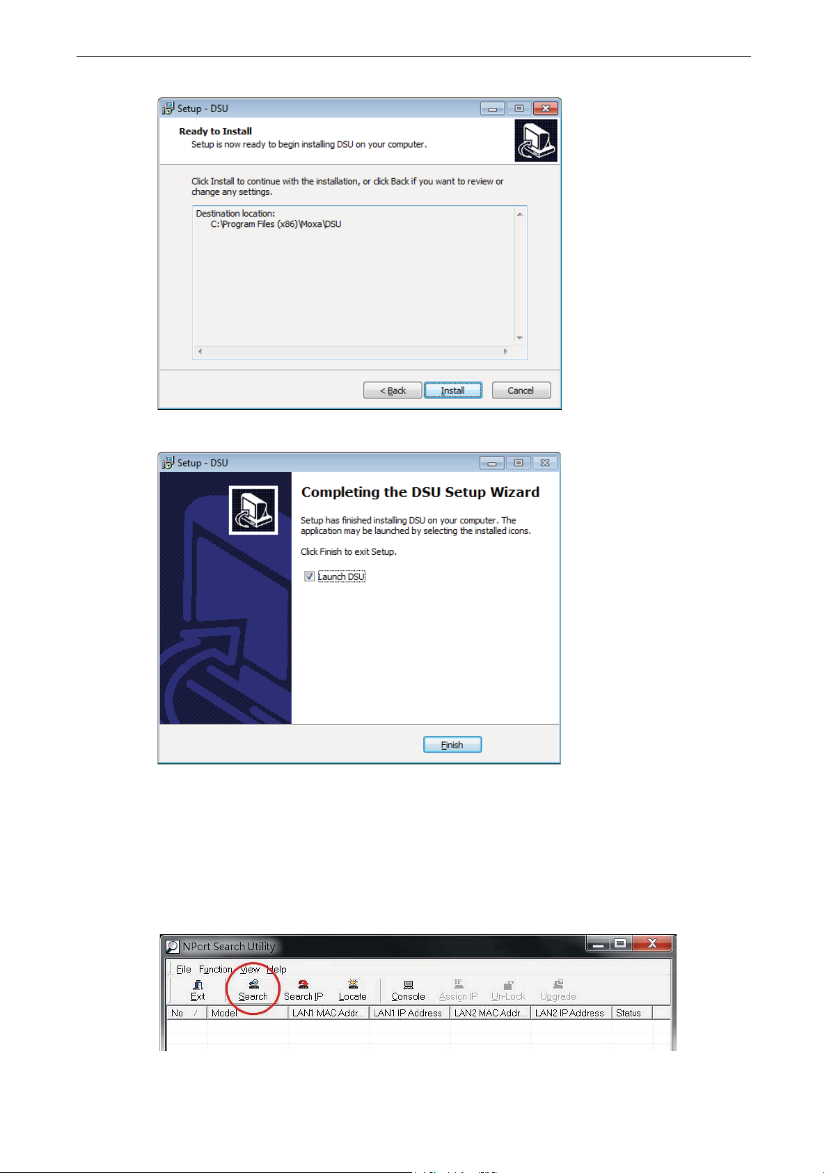
5. Verify the installation parameter s and click Install to proceed.
6. The wizard will begin installing the files . After the files have been installed, click Finish to complete the
installation.
Finding NPort Device Servers on a Network
You can use the Device Search Utility (DSU) to look up or change the IP address of any NPort device server
on the network. Since the utility searches for devices based on their MAC address rather than IP address, all
NPort units that are connect to the LAN will be located, regar dless of whether or not they are part of the
same subnet as the host.
1. In the Device Search Utility (DSU), click Search on the main toolbar.
5-4

NPort W2150A/W2250A Se ri e s Installing and Configuring the Software
2. The utility will being searching fo r NPort device servers.
3. When the search is complete, the NPort units that were found w ill be lis ted in the main window .
Modifying NPort IP Addresses
1. Once the Device Search Utility (DSU) has found NPort device servers on the LAN, you can modify any
unit’s IP address. Select the desired NPort in the main window and click Assign IP on the main toolbar.
This will modify the IP address for the active netw ork connection (LAN or WLAN).
2. Enter the new IP address and netmask. If multiple units were selecte d , you may assig n address e s
sequentially by clicking Assign IP Sequentially. Click OK to proceed.
5-5

NPort W2150A/W2250A Se ri e s Installing and Configuring the Software
3. The selected NPort will be restarted by the Device Search Utility (DSU) with the new IP address.
Upgrading NPort Firmware
1. Once the Device Search Utility (DSU) has found NPort device servers on the LAN, you can upgrade any
unit’s firmware. Right-click the des ir ed NPor t in the main window and se le c t Upgrade.
2. Select the new firmware file and click OK to proceed. To obtain the latest firmware for the NPort
W2150A/W2250A, vis it www.moxa.com.
5-6

NPort W2150A/W2250A Se ri e s Installing and Configuring the Software
3. The utility will begin upgrading the firmware for the selected unit. Do not disconnec t or power off the
unit while the firmware is being upgraded.
4. When the displayed status is OK, click Close to complete the process.
ATTENTION
The Device Search Utility (DSU) s u p por ts upgrading the firmware of multiple units simultaneo us ly if each
unit is the same model. Hold down the CTRL key to add additional units to your selection; hold down the
SHIFT key to select a block of units.
NPort Windows Driver Manager
NPort Windows Driver Manager installs remo te NPort serial ports as new COM ports on your Windows PC.
When the drivers are installed and configured , devices that are attached to serial ports on the NPort will be
treated as if they were attached to your PC’s ow n COM ports. The NPor t serial p ort must be configured for
Real COM mode when bein g mapped to a COM port.
Installing NPort Windows Driver Manager
1. Download the NPort Windows Driver Manager from Moxa website:
https://www.moxa.com/support/download.aspx?type=support&id=974
You may double click on the executable file. Once the installation p ro gr am star ts running, click [Yes] to
proceed.
5-7

NPort W2150A/W2250A Se ri e s Installing and Configuring the Software
2. The installation wizard will open. Click Next to proce ed .
3. Select a destination location and click Next to proceed.
5-8

NPort W2150A/W2250A Se ri e s Installing and Configuring the Software
4. Select a folder for the program shortcuts and click Next to proceed.
5. Verify the installation parameter s and click Install to proceed.
5-9

NPort W2150A/W2250A Se ri e s Installing and Configuring the Software
6. If you see a warning that the software has not passed Windows Logo testing, click
Continue Anyway to proceed.
7. The wizard will begin installing the files . Whe n the file s have bee n ins talle d , c lick Finish to complete t he
installation.
Adding Mapped Serial Ports
NPort Windows Driver Manager adds a COM port to your PC that is mapped to an NPort serial port. The
destination NPort serial port must be set to Real COM mode.
1. In NPort Win do ws Dr i ve r Mana ge r, click Add on the main toolbar.
5-10

NPort W2150A/W2250A Se ri e s Installing and Configuring the Software
2. Click Search to search the network for NPort device serv e rs. In the list of NPort device servers that were
found, select the unit(s) that you will use for COM mapp ing and click OK.
Alternatively, you can select Input Manually and manually enter the NPort IP Address, 1st Data
Port, 1st Command Port, and Total Ports for the desired NPort unit. C lic k OK to proceed.
5-11

NPort W2150A/W2250A Se ri e s Installing and Configuring the Software
3. NPort Windows Driver Manager will list each available serial port and will automatically assign a new
COM port to each one. The new COM port will not be accessible by the hos t syste m until it has be e n
activated in NPort Windows Driver Manager . Activ a ting a mapped CO M port sav es the informatio n in the
host system registry and makes the COM port available for use. Click Yes to activate the COM port(s) at
this time; click No to activate the COM port(s) later.
4. Activated COM ports will b e listed in black; COM ports that have not been activ a te d w ill be listed in blue.
Once a COM port has been activated, the host computer will be able to communica te w ith the new CO M
port as if it were physically attached. Since the COM mappings are stored in the host system registry,
they will still be in effect if the PC is restarted or if Wind ow s Drive r Manag er is clo se d .
5-12

NPort W2150A/W2250A Se ri e s Installing and Configuring the Software
Configuring Mapped Serial Ports
1. To modify the settings of a mapped serial port, select the desired port(s) and click Setting on the main
toolbar.
2. On the Basic Setting tab, select the COM Number that will be assigned to the serial port. If you have
selected multiple ports , you can as s ig n COM number s automatically in s equential order by selecting the
Auto Enumerating COM Number for Selected Ports function.
5-13

NPort W2150A/W2250A Se ri e s Installing and Configuring the Software
3. On the Advanced Setting tab, configure Tx Mode, FIFO, and Fast Flush.
Tx Mode: In Hi-Performance mode, the driver immediately issues a “Tx Empty” response to the
program after sending data to the NPort. In Classical mode, the driver se nds the “ Tx Empty” response
after confirmation is received from the NPort. Classical mode is recommended if you want to ensure that
all data is sent out before further processing.
FIFO: This tells the driver whether or not to use the FIFO.
Network Timeout: You can use this option to prevent blocking if the target NPort is unavailable.
Fast Flush: When enabled, the driver flushes only the local buffer on the host for a Win32
PurgeComm() function call. When disab led, bo th the lo c al and re mo te b uffers are flushed. If your
application uses PurgeComm() and perfor manc e seem s sluggis h, try enabling Fast Flush.
Auto Network Re-Connection: With this option enabled, the driver will repeate d ly attemp t to re establish the TCP connection if the NPort does not respo nd to backg ro und “c heck-alive” packets
Always Accept Open Req uests: When enabled, the NPort driver will always accept requests to open a
virtual COM port, even if communications with the device can not be established. With this option, the
NPort driver will agree to open a virtual COM port on the system even if the port is blocked or the
Ethernet connection is disabled . If this is the case, the co nnecte d d evic e will not receive and transmit
data even though the system has opened a virtual COM port.
5-14

NPort W2150A/W2250A Se ri e s Installing and Configuring the Software
Drop Writing Data if Network Connection is Lost: This function will assure the data to be kept in the
buffer or dropped when networ k c o nnec tio n is los t. The b uffe r size is 4 KBytes.
Return error if network is unavailable: If this option is disabled, the dr ive r w ill no t retur n any error
even when a connection cannot be established to the NPor t. With this option enabled, calling the Win32
Comm function will result in the e rror return code “STATUS_NETWORK_UNREACHABLE” when a
connection cannot be established to the NPor t. This usually means that your host’s network connection is
down, perhaps due to a cable being disconnected. However, if you can reach other network devices, it
may be that the NPort is not powered on or is disconnected. Not that Auto Network Re-Connection
must be enabled in order to use this function.
Ignore TX Purge
Applications can use the Win32 API PurgeCom m to clear the o utp ut buffer. Outstanding overlapping
write operations will be terminated. Select the Ignore TX Purge checkbox to ignore the effect on
output data.
4. On the Serial Parameters tab, specify the communication settings that the host will use when opening
the COM port.
5-15

NPort W2150A/W2250A Se ri e s Installing and Configuring the Software
5. On the Security tab, select the Enable Data Encryption option to enable da ta to be encr yp ted when
transmitted over the COM ports. Af ter sele c ting the encryption option, select the Keep connection
option to start encrypting COM port communic atio ns immediately without restarting the COM ports. This
may speed up opening and closing of the COM port for your host, but it also causes your host to tie up
the NPort serial port so other hosts cannot use it.
6. On the IPv6 Setting tab, interface 1 and 2 are able to change.
7. Click OK when you have f inis hed co nfiguring the COM port
5-16

NPort W2150A/W2250A Se ri e s Installing and Configuring the Software
8. To save all COM mapping settings to a text file, right-click a COM port and select Export in t he cont ext
menu. After the settings have been exported to a file, they can b e impor ted on another host.
Command-Line Installation/Removal
For NPort Windows Driver Manager v1.19 and above, it comes with command line script tool – npcli.e xe for
installation, removal of the dr iver and c a p ability of configuring NPort driver functio ns .
After successfully installing NPor t Windo ws Dr ive r Manag er v1.19 (or ab ove), the default file path is
C:\Program Files\NPortDr vManager as shown below. The main files that supp ort the NPort command line
tool are npcli.exe and GIdMap.dat. You may move these two files to yo ur pr ef erred location.
5-17

NPort W2150A/W2250A Se ri e s Installing and Configuring the Software
Once NPort Windows Driver Manager v1.19 (or above) is installed, call up the cm d screen on your
computer . Ch a n ge the direct ory to the driv e where you placed the above two f il es.
Type npcli /? to get detail information of w hat command lines are supported and the function descr iptions.
The usage instructions will show up for a user’s refe rence.
-----------------------------------------------------------------------------NPort Command Line Interface Ver2.0 Build 16052400
-----------------------------------------------------------------------------Usage:
1. NPort Driver operation:
npcli /driver [/install | /uninstall | /upgrade] [PATH_NAME]
/install Install specified driver to host.
/uninstall Uninstall current installed driver from host.
/upgrade Upgrade specified driver without modifying the mapped ports.
PATH_NAME Specify the installer file of the NPort Driver Manager to install
or upgrade.
2. RealCOM port operation:
npcli /driver /add IP_ADDR /port PORT_NO /com COM_NO [/txmode [hiperf |
classical]] [/fifo [enable | disable]] [/flush [fast | normal]]
npcli /driver /remove /com [COM_NO | all]
/add Add a RealCOM with a valid IP address (IP_ADDR).
/port Specify the NPort port number (PORT_NO) to add.
/com Specify the COM number to add or remove (COM_NO).
/txmode Set the TX mode as hi-performance (hiperf) or classical. The
default is hiperf.
/fifo Set the FIFO as enable or disable. The default is enable.
/flush Set to enable fast flush(fast) or disable fast flush(normal).
The default is fast.
/remove Remove specified COM number (COM_NO) or all RealCOM ports.
3. NPort devices operation:
npcli /devicd /search
npcli /device /set ID /network [/ip IP_ADDR] [/mask SUBNET]
[/gateway IP_ADDR] [/password CIPHER]
npcli /device /apply ID [/password CIPHER]
5-18

NPort W2150A/W2250A Se ri e s Installing and Configuring the Software
/search Search the NPort and store the list to the memory.
/set Specify the ID to set. Users must specify one of the searched
NPorts for further operations. The default is 1.
/port Specify the NPort port number (PORT_NO) to set.
/password Specify the password (CIPHER) if the NPort has one.
/network Set to change the network settings.
/ip Change the IP address (IP_ADDR) of NPort.
/mask Change the subnet mask (SUBNET) of NPort.
/gateway Change the IP address (IP_ADDR) of gateway.
/apply Specify the ID to save changes and restart the NPort.
4. Examples
npcli /driver /install D:\Users\drvmgr_setup_Ver1.19.0_Build_15122492
npcli /driver /uninstall
npcli /driver /add 192.168.127.254 /port 1 /com 3
npcli /driver /add 192.168.127.254 /port 2 /com 4 /flush normal
npcli /device /search
npcli /device /set 1 /network /ip 192.168.10.7 /mask 255.255.255.0
/password moxa
npcli /device /apply 1
Note:
Npcli.exe requires an administrator privilege to change device settings.
It support only IPv4 and it must be run under Windows XP and later versions.
Linux Real TTY Drivers
Real TTY driver are provided that will map Linux host TTY ports to NPort serial por ts . Once the mapp ing has
been set up, Linux users and applications can connect to a serial port as if it were a local TTY port. The se
drivers have been designed and te s ted for the major ity of Linux distributions, including Linux kernel version
2.4.x, 2.6.x, and 3.x, 4.x. Please check http://www.moxa.com
Basic Steps
Follow these instructio ns to map a TTY por t to an NPort serial port:
1. Install the NPort device server and set the target dev ic e port to Real COM mode.
2. Install the Real TTY driver files on the Linux host.
3. Map the host’s TTY port to the target dev ic e po rt on the NPort.
Installing Linux Real TTY Driver Files
Before proceeding with the softw a re ins tallatio n, make sure you have completed the NPort devic e server has
been installed and configured correctly. Note that the default LAN IP address for the NPort is
192.168.126.254, whereas the default WLAN IP address is 192.168.127.254.
for the latest Linux kernel supported.
ATTENTION
The target serial port must be operating in Real COM mode in order to map TTY ports.
1. Obtain the driver file from https://www.moxa.com/support/support_home.aspx?isSearchShow=1
2. Log in to the console as a super user (root).
3. Execute cd / to go to the root directory.
5-19
.

NPort W2150A/W2250A Se ri e s Installing and Configuring the Software
4. Copy the driver fi le npreal2xx.tgz to the / directory.
5. Execute tar xvfz npreal2xx.tgz to extract all files into the system.
6. Execute /tmp/moxa/mxinst. (For Red Hat AS/ES /W S an d F e dora Core1, execute
“# /tmp/moxa/mxinst SP1”.) The shell script will install the dr iver files automatically.
7. After installing the driver , yo u will b e ab le to see seve ral files in the /usr/lib/npreal2/driver folder:
mxaddsvr (add server, map TTY port)
mxdelsvr (delete server, undo TTY port mapping)
mxloadsvr (reload s erver )
mxmknod (create device node/TTY port)
mxrmnod (remove device node/TTY port )
mxuninst (remove TTYport and driver files)
At this point, you may map the TTY port to the NPort serial port.
Mapping TTY Ports
Make sure that you set the operation mode of the de s ire d NPo rt serial port to Real COM mode. After logg ing
in as a super user, enter the directory /usr/lib/npreal2/driver and then execute mxaddsvr to map the
target NPort serial port to the host TTY ports. The syntax of mxaddsvr is as follows:
mxaddsvr [NPort IP Address] [Total Ports] ([Data port] [Cmd port])
The mxaddsvr command performs the following actions:
1. Modify npreal2d.cf.
2. Create TTY ports in directory /dev with major and minor number configured in npreal2d.cf.
3. Restart the driver.
Mapping TTY ports automa ticall y
To map TTY ports automatically, you may execute mxaddsvr w ith just the IP address and number of ports,
as in the following example:
# cd /usr/lib/npreal2/driver
# ./mxaddsvr 192.168.3.4 16
In this example, 16 TTY ports will be added, all with IP 192.168.3.4, with data ports from 950 to 965 and
command ports from 966 to 981.
Mapping TTY ports manuall y
To map TTY ports manually, you may execute mxaddsvr and manually specify the data and command
ports, as in the following example:
# cd /usr/lib/npreal2/driver
# ./mxaddsvr 192.168.3.4 16 4001 966
In this example, 16 TTY ports will be added, all with IP 192.168.3.4, with data ports from 4001 to 4016 and
command ports from 966 to 981.
Removing Mapped TTY Ports
After logging in as root, enter the directory /usr/lib/npreal2/driver and then execute mxdelsvr to
delete a server. The syntax of mxdelsvr is:
mxdelsvr [IP Address]
Example:
# cd /usr/lib/npreal2/driver
# ./mxdelsvr 192.168.3.4
The following actions are performed when executing mxdelsvr:
5-20

NPort W2150A/W2250A Se ri e s Installing and Configuring the Software
1. Modify npreal2d.cf.
2. Remove the relevant TTY ports in directory /dev.
3. Restart the driver.
If the IP address is not provided in the command line , the program will list the installed servers and total
ports on the screen. You will need to choose a server from the list for deletion.
Removing Linux Driver Files
A utility is included that will remove all dr ive r files, mapped TTY ports, and unload the driver. Enter the
directory /usr/lib/npreal2/driver and execute mxuninst to uninstall the driver. This program will
perform the following actions:
1. Unload the driver.
2. Delete all files and directories in /usr/lib/npreal2.
3. Delete directory /usr/lib/npreal2.
4. Modify the system initializing scr ip t file .
UNIX Fixed TTY Drivers
A fixed TTY driver is provided that will map UNIX host TTY por ts to NPor t serial po r ts . Once the mapping has
been set up, UNIX users and applications can connect to an NPort serial port as if it were a local TTY port.
This driver has been designed and tested for the majority of UNIX systems. Please check
http://www.moxa.com
for the latest UNIX systems support.
Installing the UNIX Driver
1. Log in to UNIX and create a directory for the MOXA TTY. To create a dire c tory named /usr/etc, execute
the command:
# mkdir –p /usr/etc
2. Copy moxattyd.tar to the directory you created. For the /usr/etc directory, you would execute the
following commands:
# cp moxattyd.tar /usr/etc
# cd /usr/etc
3. Extract the source files from the tar file by executing the command :
# tar xvf moxattyd.tar
The following files will be extrac ted:
README.TXT
moxattyd.c --- source code
moxattyd.cf --- an empty configuration file
Makefile --- makefile
VERSION.TXT --- fixed TTY driver version
FAQ.TXT
4. Compile and link.
For SCO UNIX:
# make sco
For UnixWare 7:
# make svr5
For UnixWare 2.1.x, SVR4.2:
# make svr42
5-21

NPort W2150A/W2250A Se ri e s Installing and Configuring the Software
Configuring the UNIX Driver
Modify the configura tio n:
The configuration used by moxattyd is defined in the text file moxattyd.cf, which is in the same directory.
You may use vi or any text editor to modify the file, as follows:
ttyp1 192.168.1.1 950
You can refer to moxattyd.cf for detailed descriptions of the v ar io us conf iguration parameters. Please note
that Device Name depends on the OS. See the Device Naming Rule section in README.TXT fo r more
information.
To start the moxattyd daemon after sys te m bo o tup, add an entry into /etc/inittab using the TTY name
you defined in moxattyd.cf, as in the following example:
ts:2:respawn:/usr/ etc/moxattyd/mox at tyd –t 1
Device naming rule
For UnixWare 7, UnixWare 2.1.x, and SVR4.2, use:
pts/[n]
For all other UNIX operating syste ms , use :
ttyp[n]
The value of [n] should be equal or larger than 11 in ord er to pr ev e nt co nflicts with the device names of
functional keys in some UNIX systems.
Starting moxattyd
Execute the command in it q or reboot your UNIX operating system.
Adding an additional serve r
Modify the text file moxattyd.cf to add an additional server. Users may use vi or any text editor to modify
the file. For more configuration inf or m atio n, refer to moxattyd.cf, which contains detailed descriptions of
the various configuration parameters.
Find the process ID (PID) of the moxattyd.
# ps -ef | grep moxattyd
Update the configuration of moxattyd.
# kill -USR1 [PID]
(e.g., if moxattyd PID = 404, kill -USR1 404)
This completes the proce s s of adding an additional server.
5-22

6. Web Console: Basic Settings
The following topics are covered in this chapte r:
Overview
Basic Settings
6

NPort W2150A/W2250A Series Web Console: Basic Settings
Overview
This chapter introduces the NPort web cons ole and explains how to configure the basic settings.
The NPort can be configured fro m anywhe re on the network through its web console . Simply point the
browser to the device server’s IP address to open the web conso le . Network settings, operation mode, and
other items can all be configured through the bro wser.
Web Browser Settings
In order to use the web console, you will need to have cookies
enabled for your brows er . Pleas e note that the web console uses
cookies only for password transmission. For Internet Explorer,
cookies can be enabled by right-clicking the Internet Explorer ico n on
your desktop and se le cting Properties from the context menu.
On the Security tab, click Custom Level… and enable these two
items:
Allow cookies that are stor ed on yo ur com pu te r
Allow per-session cookies (not stored)
ATTENTION
If you are not using Internet Explore r, cookies are usually enabled through a web brow se r setting such as
allow cookies that are stored on your computer or allow per-session cookies.
Navigating the Web Console
To open the web console, enter your device server’s IP address in the website address line. If you are
configuring the NPort for the firs t time over an Ethe rnet cable, you will use the default IP address,
192.168.126.254.
There are two account types: admin and user. If you enter the system with admin account, you will have
the right to read and write. If you enter the system with user account, you will only have the right to read.
If prompted, enter the console password. The default password for both admin and user accounts is
moxa. The password will be transmitted with MD5 encr yp tion over the Ethernet.
6-2

NPort W2150A/W2250A Series Web Console: Basic Settings
ATTENTION
If you have forgotten the password , yo u can use the r ese t button to load factory defaults, but this will erase
all previous configuration informatio n.
The web console will appear as shown below.
Settings are presented on pages that are organized by folder. Select the desired folder in the left navigation
panel to open that page. The page will be displayed in the main window on the right. Certain folders can be
expanded by clicking the adjacent “–” symbol.
For example, if you click Basic Settings in the navigation panel, the main window will show a page of basic
settings that you can configure.
After you have made changes on a page, you must click [Submit] in the main window before jumping to
another page. Your changes will be los t if you do not c lick [Submit].
Once you click [Submit] button, the device serv er will reb oo t and w ith a be ep alar m.
6-3

NPort W2150A/W2250A Series Web Console: Basic Settings
Basic Settings
On the Basic Settings page, you can configure Server name, Server location, Time zone (24-hour),
Local time, and Time server.
Server Name
Default NPortW2150A_<serial no.> or NPor tW2250A_<serial no.>
Options free text (e.g., “Server 1” )
Description This is an optional free text field to help you differentiate one device server from another.
It does not affect operation of the NPort device server.
Server Location
Default
Options free text (e.g., “Bldg 1, 2nd Floor”)
Description This is an optional free text field to help you differentiate one device server from another.
It does not affect operation of the NPort device server.
Time Zone
Default (GMT)Greenwich Mean Time
Options (GMT)Greenwich Mean Time
(GMT-01:00)Azores, Cape Verde Is.
(GMT-02:00)Mid-Atlantic etc .
Description This field shows the currently selected time zone and allows you to select a different time
zone.
6-4

NPort W2150A/W2250A Series Web Console: Basic Settings
Local Time
Default
Options Date (yy:mm:dd), Time (hh:mm:ss)
Description The NPort has a built-in real-time clock that allow s yo u to add time info rmation to
functions such as the automatic warning e-mail or SNMP trap. This field shows the current
time according to the NPort’s built-in real-time c lo c k. This is not a live field, so you will
need to refresh the browser to get an updated reading.
Change the correct date or time, and click [Submit]. The change will take effect dire c tly,
and shows Basic Setting OK!.
ATTENTION
There is a risk of an explosion if the real-time clock battery is rep la c e d inc orre ctly!
The real-time clock is powered by a lithium battery. We strongly recommend that you obtain assistance
from a Moxa support engineer bef ore replacing the battery. Please co ntac t the Moxa RMA service team if
you need to change the battery.
Time Server
Default
Options IP address or domain name (e.g., “192.168.1 .1” or “time.nis t.gov”)
Description This optional field specifie s your time server’s IP address or domain name, if a time server
is used in your network. The NPort supports SNTP (RFC-1769) for automatic time
calibration. The device serv er will r e q uest time information from the specified time server
every 10 minutes.
6-5

7. Web Console: Network Settings
The following topics are covered in this chapte r:
Overview
Network Settings
¾ General Settings
¾ Ethernet/Bridge Settings
¾ WLAN Settings
¾ Advanced Settings
7

NPort W2150A/W2250A Se ri e s Web Console: Network Se tti ngs
Overview
This chapter explains how to configure all settings located under the Network Settings folder in the NPort
web console.
Network Settings
General Settings
On the General Settings page in the Network Setting s fo lde r, y o u can mod ify DNS serve r 1 and 2.
DNS Server 1 and 2
Default
Options IP address (e.g., “192.16 8.1.1”)
Description This field is for the DNS server’ s I P addr ess, if applicable. With the DNS server configured,
the NPort device server can use domain names instead of IP addresses to access hosts.
Domain Name System (DNS) is how Internet domain names are identified and translated
into IP addresses. A domain name is an alphanumeric name, such as www.moxa.com, that
it is usually easier to remember than the numeric IP address. A DNS server is a host that
translates a text-based domain name into an IP address in order to establish a TCP/IP
connection. When the user wants to visit a particular website , the us er ’ s computer send s
the domain name (e.g., www.moxa.com) to a DNS server to request that website ’ s
numeric IP address. When the IP address is received from the DNS server, the user’s
computer uses that information to connect to the website’ s web server.
The NPort will play the role of a DNS client, actively querying the DNS server for the IP
address associated with a particular domain name.
7-2

NPort W2150A/W2250A Se ri e s Web Console: Network Se tti ngs
Ethernet/Bridge Settings
To enable the Ethernet-to-Wireles s func tio n, als o c alle d Wire le s s Client, go to the Ethernet/Bridge
Settings page and enable Ethernet Bridge. When it's enabled, the LAN and WLAN will use the same IP
configuration (use the same IP address, netmask and g ateway s e ttings).
ATTENTION
In dynamic IP environments, the NPort w ill send thre e r eq uests ev e ry 30 seconds to the DHCP or BOOTP
server until the network settings have succ ess fully been assigned. The first request will time out after one
second; the second request will time out after thre e se conds , and the thir d req ue s t will timeo ut afte r five
second. If the DHCP or BOOTP server is unavailable , the NPort will use the f a c tory def ault ne tw ork settings.
7-3

NPort W2150A/W2250A Se ri e s Web Console: Network Se tti ngs
Ethernet Bridge
Default Disabled
Options Enabled, Disabled
Description This field specifies whether to enable Ethernet Bridge mode or not. When Ethernet
Bridge is enabled, the LAN and WLAN interfaces are bridged together. Data can be
seamlessly transferred between serial lines, LA N, and WLAN. The LAN and WLAN will use
the LAN IP setting, and WLAN IP setting will be disabled.
Disabled: When disabled, you can use either the LAN or WLAN.
Enabled: When enabled, you can use both the LAN and the WLAN.
IP Configuration
Default Static
Options Static, DHCP, DHCP/BOOTP, BOOTP
Description This field determines how the NPort’s IP address will be assigned.
Static: IP address, netmask, and gateway are user -d ef ine d .
DHCP: IP address, netmask, gateway, DNS, and time server are assigned by the DHCP
server.
DHCP/BOOTP: IP address, netmask, gateway, DNS, and time server are assigned by the
DHCP server. IP address is assigned by BOOTP server if DHCP server does not respond.
BOOTP: IP address is assigned by the BOOTP server.
IP Address
Default 192.168.126.254
Options IP address (e.g., “192.16 8.1.1”)
Description This field is for the IP address that will b e ass igned to your NPort device server. An IP
address is a number assigned to a network device (such as a compute r ) as a permane nt
address on the network. Computers use the IP address to identify and talk to each other
over the network. Choose a prop er I P addr es s that is unique and valid in your network
environment. If your device server will be assigned a dynamic IP address, set the IP
configuration parameter appropriately.
7-4

NPort W2150A/W2250A Se ri e s Web Console: Network Se tti ngs
Netmask
Default 255.255.255.0
Options Netmask setting (e.g., “255.255 .0.0 ” )
Description This field is for the subnet mask. A subnet mask represents all of the network hosts at one
geographic location, in one building , or on the same local area network (LAN). When a
packet is sent out over the network, the NPort device server will use the subnet mask to
check whether the desired TCP/I P ho s t spec ified in the packet is on the local network
segment. If the address is on the same network segme nt as the devic e serv er, a
connection is established directly from the device server. Otherwise, the connec tion is
established through the gateway as specif ied in the Gateway parameter.
Gateway
Default
Options IP address (e.g., “192.16 8.1.1”)
Description This field is for the IP address of the g ate w ay , if app lic ab le. A gateway is a network
computer that acts as an entrance to another network. Usually, the computers that control
traffic within the network or at the lo c al I nter ne t se rv ic e pr ovider are gateway nodes. The
NPort device server needs to know the IP address of the default gateway computer in
order to communicate with the hosts outside the lo c al network e nvironment. Consult your
network administrator if you do not know how to se t this parame te r.
7-5

NPort W2150A/W2250A Se ri e s Web Console: Network Se tti ngs
WLAN Settings
WLAN
The WLAN page is located under WLAN Settin gs in the Network Settings folder. You can modify IP
configuration, IP addre ss, Netmask, and Gateway for your WLAN.
The NPort W2150A/W2250A Series supports I EEE 802.11a/b/g/n wireless network interfaces. The supported
IP configurations are static and dynamic (BOOTP, DHCP, or BOO TP+D HC P). Users can set up the IP
configuration with the serial conso le , or the Web/Te lne t co nsole s thr o ugh the NPor t’ s Etherne t inte rface. For
detailed information about configur ing IP configuration, IP addr ess, Netmask, and Gateway, see the
previous section, Ethernet Configuration.
IP Configuration
Default Static
Options Static, DHCP, DHCP/BOOTP, BOOTP
Description This field determines how the NPort’s IP address will be assigned.
Static: IP address, netmask, and gateway are user -d ef ine d .
DHCP: IP address, netmask, gateway, DNS, and time server are assigned by the DHCP
server.
DHCP/BOOTP: IP address, netmask, gateway, DNS, and time server are assigned by the
DHCP server. An IP address is assigned by the BOOTP server if the DHCP server does not
respond.
BOOTP: An IP address is assigned by the BOOTP server.
IP Address
Default 192.168.127.254
Options IP address (e.g., “192.16 8.1.1”)
7-6

NPort W2150A/W2250A Se ri e s Web Console: Network Se tti ngs
Description This field is for the IP address that will be as s ig ned to yo ur NPor t devic e se rv er . An I P
address is a number assigned to a network device (such as a compute r ) as a permane nt
address on the network. Computers use the IP address to identify and talk to each other
over the network. Choose a proper IP address that is unique and valid in your WLAN
environment. If your device server will be assigned a dynamic IP address, set the IP
configuration parameter appropriately .
Netmask
Default 255.255.255.0
Options Netmask setting (e.g., “255.255 .0.0 ” )
Description This field is for the subnet mask. A subnet mask represents all of the network hosts at one
geographic location, in o ne building , or on the same LAN. When a packet is sent out over
the network, the NPort device server will use the subnet mask to check whether the
desired TCP/IP host specified in the packet is on the local network segment. If the address
is on the same network segment as the device server, a connection is establis he d dire c tly
from the device server. Otherwise, the connection is established through the gateway as
specified in the Gateway parame t er.
Gateway
Default
Options IP address (e.g., “192.16 8.1.1”)
Description This field is for the IP address of the g ate w ay , if app lic ab le. A gateway is a network
computer that acts as an entrance to another network. Usually, the computers that control
traffic within the network or at the lo c al I nter ne t se rv ic e pr ovider are gateway nodes. The
NPort device server needs to know the IP address of the default gateway computer in
order to communicate with the hosts outside the lo c al network e nvironment. Consult your
network administrator if you do not know how to se t this parame te r.
7-7

NPort W2150A/W2250A Se ri e s Web Console: Network Se tti ngs
Profile
The Profile page is located under WLAN Settings in the Network Settings folder. This is where you
configure the NPort for Infrastruc ture operation. Different settings are availab le depe nd ing o n whethe r you
select Ad-hoc Mode or Infrastructure Mode.
7-8

NPort W2150A/W2250A Se ri e s Web Console: Network Se tti ngs
Network Type
Default Infrastructure Mode
Options Infrastructure Mode, Ad-hoc Mode
Description This field specifies whe ther the NPor t will o perate in Ad-hoc or Infrastructure Mode . For all
wireless networking device s , ther e are two possible modes for communication with
another wireless device. Devices that are configured for Ad-hoc Mode automatically detect
and communicate directly with each other and do not require a wireless access point (AP)
or gateway. Wireless devices that are configured for Infrastructure Mode do not
communicate directly with each other , but thro ug h a wireless access point (AP).
Devices must be configured for the same mode in order to communicate with each other.
Devices in Ad-Hoc Mode will only r ecog n ize othe r devices in Ad-Hoc Mode, and likewise for
devices in Infrastructur e Mode.
Example of Ad-Hoc Mode
Example of Infrastructure Mode
After setting the Network type, y o u will ne ed to adju s t the Gener al and Se c u r ity s ettings
to establish the wireless connectio n.
7-9

NPort W2150A/W2250A Se ri e s Web Console: Network Se tti ngs
General Settings for WLAN Profile
The General page is opened through the Profile page, under WLAN Settings in the Network Settings
folder. You can type a profile name to help yo u differentiate one profile from another . I t does not af fe c t
operation of the NPort. After selecting Ad-hoc or Infrastructure Mode , click [General] to open the General
page for the selected profile. In Ad-ho c Mode and Infrastructure Mode, on l y on e profile is available.
In Ad-hoc Mode
7-10

NPort W2150A/W2250A Se ri e s Web Console: Network Se tti ngs
In Infrastructur e Mode
On the General page, you can configure Profile name, RF type, and input an SSID provided by your Wi-Fi
AP. Additional settings are also availab le de p ending on whether you select Ad-hoc Mode or Infr as tructure
Mode.
Profile Name
Default Ad-hoc (in Ad-hoc Mode)
Infrastructure (in Infrastruc tur e Mod e )
Options free text (e.g., “Primary Connection”)
Description This is a free text field to help you differentiate one profile from another. It does not affect
operation of the NPort.
7-11

NPort W2150A/W2250A Se ri e s Web Console: Network Se tti ngs
RF Type
Default 802.11b/g for Ad-Hoc Mode.
Auto for Infrastructure Mod e .
Options Auto, 802.11a, 802.11b/g, 802.11a/n, 802.11b/g/n
Description This field determines whic h wir e le s s st and ard w ill be us ed by the sele c ted pro file. 802.11a,
802.11b/g, 802.11a/n and 802.11b/g/n are supported.
Auto: In Ad-hoc Mode, the NPort will scan the 2.4G wirele s s b and and w ill automatically
select the appropriate wireless standard for communication with any other wireless
devices that are detected. In Infrastructure Mode, the NPort will auto matically select
between 802.11a, 802.11b/g, 802.11a/n and 802.11b/g/n according to the settings of the
AP.
802.11a: The Unlicensed National I nformation Infrastructure (UNII) 5 GHz band is used
for communication, which is different fro m the RF ba nd used by 802.11b and 802.11g.
Consequently, 802.11a devices w ill not be able to communicate with 802.11b or 802.11g
devices. (Multi-mode 802.11 a/b/g A Ps or clie nt ad apte r s can be use d to re solve this.)
Transmission rates up to 54Mbps are supported.
802.11b/g: This option means our device will support for 802.11b or 802.11g.
802.11b: This is the well-known “Wi-Fi” standard, also referred to as “802.11 High-Rate
(HR).” Wireless communication is in the 2.4 GHz ISM band , using the DS SS spre ad
spectrum transmission sch eme. 802.11b support s data rates of 1 Mbps, 2 Mbps, 5.5 Mb p s ,
and 11 Mbps.
802.11a/n: This option means our device will support up to 150 Mbps data rate to
communicate with an 802.11a/n AP.
802.11b/g/n: This option means our device will support up to 72.2 Mbps data rate to
communicate to a 802.11b/g/n AP.
SSID
Default profile1
Options free text (e.g., “Coffeeshop WLAN”)
Description This field specifies the SSID, or name , of the w ire le s s network (SSID) that will be used by
the NPort. Wireless devices must use the same SSID in order to communica te with eac h
other.
Site Survey (This function is supported by firmware V1.10 or above)
When you click Site Survey, the device server will scan for all the A Ps it can find ne arby. It shows all the
signal strengths between the device server and the APs. You may check the checkbox and click OK to create
a profile for the specified AP.
7-12

NPort W2150A/W2250A Se ri e s Web Console: Network Se tti ngs
Channel (Ad-hoc mode only)
Default 1
Options 1, 2, 3, 4, 5, 6, 7, 8, 9, 10, 11
Description This field is for Ad-Hoc Mode only and sp e c ifies the radio channel to use for the wireless
network.
Fast Roaming (Infrastructure mode only)
Default Disable
Options Disable, Enable
Description This field is only available in Infras tructure Mode and is used to specify the
W2150A/W2250A roaming behavio r. Roaming is the ability to connect to differe nt APs so
that wireless communication is not confined to one are a or one particular AP. The
W2150A/W2250A will only roam between APs, as specified by the SSID.
Disable: Fast Roaming function will be disabled.
W2150A/W2250A will scan all available channels and roam between APs as specified by
the SSID. It scans the channel when booting up and will associate with the hig he s t signal
strength AP. Only when the associated AP is lost, it will re-associate again.
Enable: Fast Roaming function will be enabled.
NPort W2150A/W2250A will only scan the pre-defined Scan Channels - 1, Scan
Channels - 2 & Scan Channe ls – 3 and roam between APs as specified by the SSID.
It scans the channel and will associate with the highest signal strength AP. It also scans
the channel regularly and will re-associate with the highest signal strength AP (if there is)
automatically.
Scan channels – 1, Scan channels – 2, Scan channels – 3 (Infrastructure
mode only)
Default N/A
Options
Description This field is for fast roaming under Infrastructure Mode and specifies the radio channel to
1 through 14, 36, 40, 44, 48, 52, 56, 60, 64, 100, 104, 108, 112, 116, 120, 124, 128, 132, 136, 140,
149, 153, 157, 165
use for the wireless network. Choose the channel according to the factory setting of the
AP.
Roaming threshold (This function is supported by firmware V1.10 or above)
Default -70 (Disable)
7-13

NPort W2150A/W2250A Se ri e s Web Console: Network Se tti ngs
Options numbers
Description When the signal strength between the device and the AP is worse than this number, below
-70 dBm as the default number, the device server will s tart to scan for a new AP to
establish the connection.
Roaming difference (This function is supported by firmware V1.10 or above)
Default 2 (Disable)
Options numbers
Description When the device server finds a new AP, the signal strength between device server and the
new AP must above this number compares to the old AP, then the device server will
change to establish a new connection with the new AP. For example, when the signal
strength to the old AP is -70 dBm. When the new AP is -69 dBm, the devic e ser ver w ill
keep the connection to the old one . If the new A P is -68 dBm, the de v i c e serv e r w ill sw itc h
the connection to the new AP.
7-14

NPort W2150A/W2250A Se ri e s Web Console: Network Se tti ngs
Security Settings for WLAN Profile
The Security page is opened through the Profile page, under WLAN Settings in the Network Settings
folder. After selec ting Ad-hoc or Infrastructure Mod e , click [Security] to op e n the S ec urity page for the
selected profile. In Ad -ho c Mod e , only one pro file is available, whereas three prof ile s ar e available in
Infrastructure Mode.
In Ad-hoc Mode
7-15

NPort W2150A/W2250A Se ri e s Web Console: Network Se tti ngs
In Infrastructur e Mode
You will need to configure Authentication and Encryption. These settings must match the settings on the
wireless device at the other end of the connection (such as the AP). Different settings and options are
available depending on how Authentication and Encryption are configured.
7-16

NPort W2150A/W2250A Se ri e s Web Console: Network Se tti ngs
Authentication
Default Open System
Options Open System, Shared Key, WPA, WPA-PSK, WPA2, WPA2-PSK
Description This field specifies how wireless devices will be authenticated. Only authenticated devices
will be allowed to communicate with the NPor t. If a RADIU S serv e r is use d , this se tting
must match the setting on the RADIUS server.
Open System: The NPort will simply announce a desire to asso c iate with ano the r s tation or
access point. No authentication is re q u ire d . For Ad -hoc Mode, this is the only option for
authentication, since Ad-hoc Mode wa s desig ned for open co mmunic ation.
Shared Key: This option is only available in Infrastructure Mode. Authentication involves a
more rigorous exchange of frames to ensure that the requesting station is authentic. WEP
encryption is requir ed .
WPA: This is a managed authentication option that is only available in Infrastructure
Mode. WPA was created by the Wi-Fi Alliance, the industry trad e gro up that owns the Witrademark and certifies devices with the Wi-Fi name. It is based on Draft 3 of the IEEE
802.11i standard. Each user uses a unique key for authe nticatio n, d is tr ibuted from an
IEEE 802.1X authentication server, also known as a RADIUS server. This option is also
referred to as WPA Enterprise Mode, since it is intended to meet rigorous enterprise
security requirements. Tunne le d authe n tic ation is supported, depending on the EAP
method selected.
Fi
WPA-PSK: This is an unmanaged authentication op tion that is only available in
Infrastructure Mode. Inste a d of a uniq ue k ey for e a c h user, a pr e -s hare d ke y (PS K) is
manually entered on the access point to gener ate an en cryp tion key that is shared among
all users. Consequently, this method do e s not scale well for enterprise. A PSK that uses a
mix of letters, numbers and non-alphanumeric c harac te rs is r eco mmend ed. This op tio n is
also referred to as WPA Personal Mode, since it is designed for the needs and capabilities
of small home and office WLANs.
WPA2: This is a managed authentication option that is only available in Infrastructure
Mode. WPA2 implements the mandatory elements of 802.11i. Supported encryption
algorithms include TKIP, Michael, and A ES-bas ed CCMP, which is cons id er e d fully s ecur e .
Since March 13, 2006, WPA2 has been mandatory for all Wi-Fi-ce rtified devices. This
option may also be referred to as WPA Enterpr ise Mod e . Tunneled authentication is
supported, depending on the EAP method selected.
WPA2-PSK: This is an unmanaged authentication optio n that is only availab le in
Infrastructure Mode. It employ s WP2 encry p tion algorithms but relies on a PSK for
authentication. A PSK that uses a mix of letters, number s and non-alp hanume ric
characters is recommended. This option can also be referred to as WPA Personal Mode.
7-17

NPort W2150A/W2250A Se ri e s Web Console: Network Se tti ngs
Encryption
Default Disable
Options Disable, WEP, TKIP, AES-CCMP
Description This field specifies the type of encryption to use during wireless communication. Different
encryption methods are available depending on the Authentication setting. Also, each
encryption method has its own set of parameter s that may also req uire co nf igur ation.
Disable: No encryption is applied to the data d uring wire less communication. This option is
only available if Authentication is set to Open System.
WEP: Wired Equivalent Privacy (WEP) is only av ailable for Open System and Shared Key
authentication methods. Data is enc rypted according to a key. The NPort supports bo th 64
and 128-bit keys. This method may deter casual s nooping but is not considered very
secure.
TKIP: Temporal Key Integrity Pro tocol (TKIP) is only available for WPA, WPA2, WPA-PSK,
and WPA2-PSK authentication methods. TKIP is part of a draft s tand ard fr o m the IEEE
802.11i working group and utilizes the RC4 stream cipher with 128-bit keys for encryption
and 64-bit keys for authenticatio n. TKIP improves on WEP by adding a per-packet ke y
mixing function to de-corre late the pub lic initialization vectors (IVs) from weak keys .
AES-CCMP: This is a powerful encryption method that is only available for WPA, WPA2,
WPA-PSK, and WPA2-PSK authentication methods . Adva nc ed Enc ry p tion Standard (AES) is
the block cipher system used by the Robust Secure Network (RSN) protocol and is
equivalent to the RC4 algorithm used by WPA. CCMP is the security protocol used by AES,
equivalent to TKIP for WPA. Data undergoes a Message Integrity Check (MIC) using a
well-known and proven technique ca lle d C ipher B loc k C haining Message Authentication
Code (CBC-MAC). The technique ensures that even a one-bit alteration in a message
produces a dramatically different r e s ult. Mas ter keys ar e not use d dire ctly but are used to
derive other keys, each of which exp ir e afte r a cer tain amount of time. Messages are
encrypted using a secret 128-bit key and a 128-bit block of data. The e ncr yption process
is complex, but the administrator does not ne ed to be aware of the intr ic ac ie s of the
computations. The end result is encryption that is much harder to break than even WPA.
PSK Passphrase
Default
Options free text (e.g., “This is the WLAN passphras e”)
Description This field is only available for WPA-PSK and WPA2-PS K authenticatio n me thods. If the
NPort’s passphrase does not match the AP’s passphras e , the connec tion will be denied. A
PSK of sufficient strength—one that uses a mix of letters, numbers and non-alphanumeric
characters—is recommended.
7-18

NPort W2150A/W2250A Se ri e s Web Console: Network Se tti ngs
Security Settings for WEP Encryption
When Encryption is set to WEP on the Security page for the WLAN profile, you will be able to configure
WEP key length, WEP key index, and WEP key source. Other settings will be displayed depending on
how WEP key source is configured.
WEP Key Length
Default 64bits
Options 64bits, 128bits
Description This field specifies the le ngth of the WEP key. 64b its is the industry standard for WEP, but
128bits provid e s be tte r protection.
WEP Key Index
Default 1
Options 1 through 4
Description This field specifies the primary WEP key to use for the WLAN.
WEP Key Source
Default Manual
Options Manual, Generate WEP keys by passphrase
Description This field specifies whether the WEP key w ill be gener ated manually or through a user-
specified passphrase. A passphrase is equivalent to a free-text password that will be used
to generate the WEP key. A passphrase is typically easier to re member and enter than a
long and complicated WEP key.
WEP Passphrase
Default
Options free text (e.g., “This is the WEP passphras e”)
Description This field is only available if WEP key so urc e is se t to Generate WEP keys by
passphrase. A standard hexadecimal password will be generated using the supplied
passphrase. For example, if “404tech” is entered, the WEP key will be
“DB971608E942FC39BD89FC4ADB”.
7-19

NPort W2150A/W2250A Se ri e s Web Console: Network Se tti ngs
WEP Key Format
Default ASCII
Options ASCII, HEX
Description This field is only available if WEP key so urc e is se t to Manual. It specif ie s the for mat yo u
will use to enter the WEP key.
WEP Key 1 Th rough 4
Default
Options free text in ASCII or HEX
Description These fields are only available if WEP key sourc e is set to Manual. Enter e ac h WEP key in
ASCII or HEX as specified in WEP key format. The number of character s req uired for each
key depends on WEP key length and WEP key for m at.
WEP Key Length WEP Key Format Key Length
64bits ASCII 5 characters
HEX 10 characters
128bits ASCII 13 characters
HEX 26 characters
7-20

NPort W2150A/W2250A Se ri e s Web Console: Network Se tti ngs
Security Settings for WPA, WPA2
When WPA or WPA2 is used for authentication, you will also need to configure EAP method in the Security
settings for the WLAN profile. Other settings will also be displayed depending on how EAP method is
configured.
7-21

NPort W2150A/W2250A Se ri e s Web Console: Network Se tti ngs
There are two parts to WPA and WPA2 security , authentica tio n , and data e ncr yp tio n .
• Authentication occurs before access is granted to a WLAN. Wireless clients such as the NPort
W2150A/W2250A Series are first authe n tic ate d by the AP acco rd ing to the authentication protocol used
by the RADIUS server. Depending on the WLAN sec urity settings, an EAP tunnel can be used to scramble
the username and password that is submitted for authentication purposes.
• Encryption occurs after WLAN access has been granted. For all wireless devices, data is first encrypted
before wireless transmission, using mutually agreed-upon encryption protocol.
EAP Method
Default PEAP
Options TLS, PEAP, TTLS, LEAP
Description This field specifies the EAP method to us e fo r authe ntic ation. Four methods are supported .
TLS: Transport Layer Security (TLS) was created by Microsoft and accepted by the IETF as
RFC 2716: PPP EAP TLS Authentication Protocol. Passwords and tunneled authentication
are not used. A user certificate and user priv ate key are used to identify the NPort. The
NPort’s user certificate and user pr ivate key mus t already be installed on the RADIUS
server.
PEAP: Protected Extensible Authentica tio n Protocol (PEAP) is a proprietary pro tocol w h ic h
was developed by Microsoft, Cisco, and RSA Security.
TTLS: Tunneled Transport Layer Security (TTLS ) is a proprietary pro to col which w a s
developed by Fu nk Software and Certic om, and is supported by Ag ere Systems, Proxim ,
and Avaya. TTLS is being considered by the IETF as a new standard. For more information
on TTLS, read the draft RFC EAP Tunneled TLS Authenticatio n Pro tocol.
LEAP: Lightweight Extensible Authentic ation Protocol (LEAP) is a proprietary protoco l
which was developed by Cisco. LEAP doesn’t check certificate during the authentication
process.
Tunneled Authentication
Default PAP (when using TTLS)
GTC (when using PEAP)
Options GTC, MD5, MSCHAP V2 (when using PEAP)
PAP, CHAP, MSCHAP, MSCHAP V2, EAP-MSCHAP V2, EAP-GTC,
EAP-MD5 (when using TTLS)
Description This field specifies the encryption method to use during the authentication process.
Different methods are available, depending on the EAP Method setting.
Username
Default
Options free tex t (e .g ., “Smith_John”)
Description This field specifies the username that will be used to gain access to the WLAN. The correct
username and password must be provided for access to be granted.
7-22

NPort W2150A/W2250A Se ri e s Web Console: Network Se tti ngs
Password
Default
Options free text (e.g., “Password123”)
Description This field specifies the passwor d that w ill b e used to g a in access to the WLA N. The corr ect
username and password must be provided for access to be granted.
Anonymous Username
Default
Options free text (e.g., “Anyuser”)
Description This field specifies the anonymous username to use whe n initiating authe ntic ation. After
the RADIUS Server has been verified by certificate, the true username and password will
be used to complete the authentication pro c e ss.
Verify Server Certificate
Default Disable
Options Disable, Enable
Description Disable: The certificate from the RADIUS server will be ignored.
Enable: The certificate fro m the RADIUS server will be used to authenticate ac c ess to the
WLAN. The RADIUS server’ s tr u s t ed server certificate mu s t already be inst a l l e d on the
NPort. To install a trusted server certificate, visit the corresponding page in the System
Management> Certificate folder.
Trusted Server Certificate
This field is available for PEAP, TLS, and TTLS EAP me thod s only . It displays information on the trusted
server certificate that is installe d on the NPor t. To ins tall a trus te d se rv er certificate, visit the corresponding
page in the System Management > Certificate folder.
User Certificate
This field is available only when the EAP method has been set to TLS. It displays information on the user
certificate that is installed on the NPort. To ins tall a us er certificate, visit the corresponding page in the
System Management > Certificate folder.
User Private Key
This field is available only when EAP method has bee n set to TLS. It dis p lays information on the user private
key on the NPort.
WLAN Log Settings
7-23

NPort W2150A/W2250A Se ri e s Web Console: Network Se tti ngs
Æ
WLAN Log Settings (This function is supported by firmware V1.10 or above)
Default Disable
Options Disable, Enable
Description When the wireless connection between the device server and the AP is not stable, you
may enable this function to have more informatio n for tro ub leshooting. You may find
System Status Æ WLAN Log for the detail logs. Before calling
System Monitoring
for help from Moxa, please enable this func tio n to c o lle c t some info rmation.
Æ
Advanced Settings
On the Advanced Settings page in the Network Sett in gs folder, you can modify Gratuitous ARP. For
this function, the NPort will actively send ARP packets to inform the devices in the network how to find the
NPort. If you enable Ethernet/Bridge mode , yo u can input the IP/MA C addr ess of the legacy device that
connected to the Ethernet port o f the NPort. The NPort will help to send out the ARP packets with its I P
address to inform the network how to find this legacy device.
Gratuitous ARP
Default Enabled
Options Enable / Disable
Description Gratuitous ARP requests provide duplicate IP address detection. The NPort sends
broadcast packets to update ARP tables on other devices (e.g., AP, PC) periodically. We
can use this function to notify networked de v ices that the NPort is still alive. Moreover, the
NPort can send Gratuitous ARP for legacy devices that do not have this function.
If you want the NPort to send Gratuitous ARP for legacy devices, you should enter the
legacy devices’ IP and Mac addresses in IP/MAC address field.
Send Period
Default 180 seconds
Options 10-1000 sec onds
Description This field specifies how lo ng the NPor t periodically sends Gratuitous AR P.
IP/MAC Addresses
Default N/A
Options IP address and MAC address of the legacy device (e.g., IP: “192.168.1.1”, MAC:
“11:22:33:44:AA:11”). This function only available when Ethernet Bridge is enabled.
Description IP address: legacy device IP address.
MAC address: legacy devices MAC address.
7-24

NPort W2150A/W2250A Se ri e s Web Console: Network Se tti ngs
7-25

8. Web Console: Serial Port Settings
The following topics are covered in this chapte r:
Overview
¾ Serial Port Settings
¾ Communication Parameters
¾ Data Buffering/Log
8

NPort W2150A/W2250A Series Web Console: Serial Port Settings
Overview
This chapter explains how to configure all settings located under the Serial Port Settings folder in the
NPort web console.
Serial Port Settings
Operation Modes
Each serial port on the NPort is configured thro ugh the hyperlink below the column of Operating mode.
Click the link of Real COM, it will show the Por t se tting s page. The Operation Modes page for each s er ial
port is where you configure the serial port’s operation mode and related settings. For an introduc tion to the
different operation modes, please refer to Chapter 4.
8-2

NPort W2150A/W2250A Series Web Console: Serial Port Settings
Operation Mode
Default Real COM
Options Real COM, RFC2217, TCP Server, TCP Client, UDP, Pair_Master, Pair_Slave, EMode m
Description Along with Application, this field specifies the serial port’s operation mode, or how it will
interact with network devices . Dep e nd ing on how Applic ation is configured, different
options are available for Mode. Depend ing o n how Mode is configured, additional settings
will be available for configuration. Fo r an introduction to the different operatio n mode s ,
please refer to Chapter 4. Real COM: This serial port will operate in Real COM mode.
RFC2217: This serial po rt will operate in RFC2217 mode.
TCP Server: This serial port will oper ate in TCP Server mode.
TCP Client: This serial port will operate in TCP Client mod e .
UDP: This serial port will operate in UDP mode.
Pair_Master: This serial port will oper ate in Pair Co nne c tio n Master mod e .
Pair_Slave: This serial port will oper ate in Pair Co nne c tio n Slave mode .
EModem: This serial port will operate in Ether ne t Modem mode.
8-3

NPort W2150A/W2250A Series Web Console: Serial Port Settings
Settings for Real COM Mode
When Operation Mode is set to Real COM on a serial port’s Operation Modes page, you will be able to
configure additional settings including TCP alive check time, Max connection, Ignore jammed IP,
Allow driver Control, Connection goes down, Packet length, Delimiter 1, Delimiter 2, Delimiter
process, and Force transmit.
TCP Alive Check Time
Default 7 min
Options 0 to 99 min
Description This field specifies how long the NPort will wait for a response to “keep-alive” packets
before closing the TCP connection. The NPor t c heck s conne ctio n s tatus by send ing p er iod ic
“keep- a l i ve” packets .
0: The TCP connection will remain open even if there is no respo n s e to the “k eep -alive”
packets.
1 to 99: If the remote host does not respond to the packet within the specified time, the
NPort will force the existing TCP connection to close.
8-4

NPort W2150A/W2250A Series Web Console: Serial Port Settings
Max connection
Default 1
Options 1 to 8
Description This field specifies the maximum number of connections that will be accepted by the serial
port.
1: Only one specific host can access this serial port, and the Real COM driver on that host
will have full control over the port.
2 to 8: This serial port will allow the specified number of connections to be opened
simultaneously. With simultaneous conne c tions, the Real COM driver will only provide a
pure data tunnel with no control ability. The serial communic ation will be determined by
the NPort rather than by your application program. Application software that is based on
the Real COM driver will receive a driver response of “success” when using any of the
Win32 API functions. The NPort will se nd data only to the Real C O M driv er on the ho s t.
Data received from hosts will be sent to the attached serial device on a first-in-first-out
basis.
ATTENTION
When Max connection is two or greater, the serial port’s communication settings (i.e., baudrate, parity, data
bits, etc.) will be determined by the NPor t. Any host that opens the COM port connection must use identical
serial communication settings.
Ignore jammed IP
Default Disable
Options Disable, Enable
Description This field specifies how an unresponsive IP addre s s is hand led when ther e are
simultaneous connections to the serial port.
Disable: All transmission will be suspended if one IP address becomes unresponsive.
Transmission will only resume when all hos ts hav e res po nd ed.
Enable: Data transmission to the other hosts will not be suspended if one IP address
becomes unresponsive.
Allow driver control
Default Disable
Options Disable, Enable
Description This field specifies how the port will proceed if driver control commands are received from
multiple hosts that are connected to the port.
Disable: Driver control commands will be ignored.
Enable: Control commands will be accepted, with the mos t rece nt co mmand rec e ive d
taking precedence.
Connection goes down
Default always high
Options always low, always high
Description This field specifies what happens to the RTS and DTR signals when the Ethernet
connection goes down. For some applications, ser ial devices need to know the Ethernet
link status through RTS or DTR signals sent through the serial port.
Always low: The selected signal will change to low when the Ethernet connection goes
down.
Always high The selected signal will remain high when the Etherne t co nne c tio n go es down.
8-5

NPort W2150A/W2250A Series Web Console: Serial Port Settings
Packet length
Default 0
Options 0 to 1024
Description This field specifies the maximum amount of data that is allowed to accumulate in the serial
port buffer before sending.
0: Packet length is disregarded and data in the buffer will be sent as specified by the
delimiter settings or when the buffer is full.
1 to 1024: Data in the buffer will be sent as soon it reaches the spe c ified length.
Delimiter 1 and 2
Default Disabled
Options Disabled, Enabled, 00 to FF
Description These fields are used to define special delimiter charac ter(s) f or data pac k ing. Enable
Delimiter 1 to control data packing with a single character; enable both Delimiter 1 and 2
to control data packing with two characters received in sequence.
When these fields are enabled, serial data will accumulate in the serial port’s buffer until
the buffer is full or until the specified delimite r cha r a cter(s) are received. For exam p le , the
carriage return character could be used as a delimiter in order to transmit each sentence
or paragraph in a separate pack et. Data will be packed according to Delimiter process.
Delimiters must be incorporate d into the data stream at the software or device level.
ATTENTION
When Delimiter 1 is enabled, Packet length must be set to 0.
Delimiter process
Default Do Nothing
Options Do Nothing, Delimiter + 1, Delimiter + 2, Strip Delimiter
Description This field specifies how data is pack ed whe n de limite r characters are received. This field
has no effect if Delimiter 1 is not enabled.
Do nothing: Data accumulated in the serial port’s buff er will be pack ed, inc lud ing
delimiters.
Delimiter + 1: One additional character mus t be rec e ive d bef ore the data in the serial
port’s buffer is packed.
Delimiter + 2: Two additional characters must be received before the data in the serial
port’s buffer is packed.
Strip Delimiter: Data accumulated in the serial port’s buffer will be packed, but the
delimiter character(s ) will be str ip p ed fro m the data.
8-6

NPort W2150A/W2250A Series Web Console: Serial Port Settings
Force transmit
Default 0 ms
Options 0 to 65535
Description This field controls data pack ing by the amount of time that elapses between bits of data.
When using this field, make sure that Inactivity time is dis abled or set to a larger value.
Otherwise the connection may be closed before the data in the buffer can be transmitted.
0: If serial data is not received, the NPort will wa it ind ef inite ly for additional data.
1 to 65535: If serial data is not received fo r the sp ecified amount of time, the data that is
currently in the buffer will be pac ked fo r ne two rk transmission. The optimal force transmit
time depends on your application, but it must be at least larger than one character
interval within the specified baudrate . For ex ample, assume that the ser ial por t is set to
1200 bps, 8 data bits, 1 stop bit, and no parity. In this ca s e, the total number of bits
needed to send a character is 10 bits, and the time re q uired to transfer one character is
8.3 ms, so the force transmit time to be larger than 8.3 ms.
Settings for RFC2217 Mode
When Operation Mode is set to RFC2217 on a serial port’s Operation Modes page, you will be able to
configure additional settings, includ ing TCP alive check time, TCP port, Packet length, Delimiter 1,
Delimiter 2, Delimiter process, and Force tr an smit.
TCP alive check time
Default 7 min
Options 0 to 99 min
Description This field specifies how long the NPort will wait for a response to “keep-alive” packets
before closing the TCP connection. The NPor t c heck s conne ctio n s tatus by send ing p er iod ic
“keep-alive” packets.
0: The TCP connection will remain open even if there is no response to the “keep-alive”
packets.
1 to 99: If the remote host does not respon d to the p ack e t within the sp e c ified time, the
NPort will force the existing TCP connection to close.
8-7

NPort W2150A/W2250A Series Web Console: Serial Port Settings
TCP port
Default 4001
Options
Description This field specifies the TCP por t number that the serial port will use to listen to
connections, and that other devices must use to contact the serial port.
Packet length
Default 0
Options 0 to 1024
Description This field specifies the maximum amount of data that is allowed to accumulate in the serial
port buffer before sending.
0: Packet length is disregarded and data in the buffer will be sent as specified by the
delimiter settings or when the buffer is full.
1 to 1024: Data in the buffer will be sent as soon it reaches the spe c ified length.
Delimiter 1 and 2
Default Disabled
Options Disabled, Enabled, 00 to FF
Description These fields are used to define special delimiter charac ter(s) f or data pac k ing. Enable
Delimiter 1 to control data packing with a single character; enable both Delimiter 1 and 2
to control data packing with two characters received in sequence.
When these fields are enabled, serial data will accumulate in the serial port’s buffer until
the buffer is full or until the specified delimite r cha r a cter(s) are received. For exam p le , the
carriage return character could be used as a delimiter in order to transmit each sentence
or paragraph in a separate pack et. Data will be packed according to Delimiter process.
Delimiters must be incorporate d into the data stream at the software or device level.
Delimiter process
Default Do Nothing
Options Do Nothing, Delimiter + 1, Delimiter + 2, Strip Delimiter
Description This field specifies how data is packed when delimiter characters are received. This field
has no effect if Delimiter 1 is not enabled.
Do nothing: Data accumulated in the serial port’s buff er will be pack ed, inc lud ing
delimiters.
Delimiter + 1: One additional character mus t be received before the data in the serial
port’s buffer is packed.
Delimiter + 2: Two additional characters must be received before the data in the serial
port’s buffer is packed.
Strip Delimiter: Data accumulated in the serial port’s buffer will be packed, but the
delimiter character(s ) will be str ip ped from the data.
8-8

NPort W2150A/W2250A Series Web Console: Serial Port Settings
Force transmit
Default 0 ms
Options 0 to 65535
Description This field controls data pack ing by the amount of time that elapses between bits of data.
When using this field, make sure that Inactivity time is disable d or set to a larg er value .
Otherwise the connectio n may be clos e d be fo re the data in the buffer can be transmitted.
0: If serial data is not received, the NPort will wa it ind ef inite ly for additional data.
1 to 65535: If serial data is not received fo r the specified amount of time, the data that is
currently in the buffer will be packed for network transmission. The optimal force transmit
time depends on your application, but it must be at least larger than one character
interval within the specified baudrate . For ex ample, assume that the ser ial por t is set to
1200 bps, 8 data bits, 1 stop bit, and no parity. I n this ca s e, the total number of bits
needed to send a character is 10 bits, and the time required to transfer one character is
8.3 ms, so the force transmit time to be larger than 8.3 ms.
Settings for TCP Server Mode
When Operation Mode is set to TCP Server on a serial port’s Operation Modes page, you will be able to
configure additional settings such as TCP alive check time, Inactivity time, Max connection, Ignore
jammed IP, Allow driver control, TCP port, Cmd port, Connection goes down, Packet length,
Delimiter 1, Delimiter 2, Delimiter process, and Force transmit.
8-9

NPort W2150A/W2250A Series Web Console: Serial Port Settings
TCP alive check time
Default 7 min
Options 0 to 99 min
Description This field specifies how long the NPort will wait for a response to “keep-alive” packets
before closing the TCP connection. The NPor t c heck s conne ctio n s tatus by send ing p er iod ic
“keep-alive” packets.
0: The TCP connection will remain open even if there is no respo ns e to the “k eep -alive”
packets.
1 to 99: If the remote host does not respon d to the p ack e t within the sp e c ified time, the
NPort will force the existing TCP connection to close.
Inactivity time
Default 0 ms
Options 0 to 65535 ms
Description This field specifies the time limit for keeping the connection open if no data flows to or
from the serial device.
0: The connection will remain open even if data is never re ceiv e d. For many applications,
the serial device may be idle for long periods of time, so 0 is an appropriate setting.
1 to 65535: If there is no activity for the specif ied time , the c o nnection will be closed.
When adjusting this field, make sure that it is greater than the Force transmit time.
Otherwise, the TCP connection may be c los e d be fo re data in the b uffer can be transmitted.
Max connection
Default 1
Options 1 to 8
Description This field specifies the maximum number of connections that will be accepted by the serial
port.
1: Only one specific host can access this serial port, and the Real COM driver on that host
will have full control over the port.
2 to 8: This serial port will allow the specified number of connections to be opened
simultaneously. With simultaneous conne c tions, the Real COM driver will only provide a
pure data tunnel with no control ability. The serial communic ation will be determined by
the NPort rather than by your application program. Application software that is bas ed on
the Real COM driver will receive a driver response of “success” when using any of the
Win32 API functions. The NPort will se nd data only to the Real COM driver on the host.
Data received from hosts will be sent to the attached serial device on a first-in-first-out
basis.
ATTENTION
When Max connection is two or greater, the serial po r t’ s communicatio n s e tting s (i.e ., b audrate, parity, data
bits, etc.) will be determined by the NPor t. Any host that opens the COM port connection must use identical
serial communication settings.
8-10

NPort W2150A/W2250A Series Web Console: Serial Port Settings
Ignore jammed IP
Default Disable
Options Disable, Enable
Description This field specifies how an unresponsive IP addre s s is hand led when ther e are
simultaneous connections to the serial port.
Disable: All transmission will be suspended if one IP address becomes unresponsive.
Transmission will only resume when all hos ts hav e res po nd ed.
Enable: Data transmission to the other hosts will not be suspended if one IP address
becomes unresponsive.
Allow driver control
Default Disable
Options Disable, Enable
Description This field specifies how the port will proceed if driver control commands are received from
multiple hosts that are connected to the port.
Disable: Driver control commands will be ignored.
Enable: Control commands will be accepted, with the mos t rece nt co mmand rec e ive d
taking precedence.
TCP port
Default 4001
Options 0 to 9999
Description This field specifies the TCP por t number that the serial port will use to listen to
connections, and that other devices must use to contact the serial port.
Cmd port
Default 996
Options
Description This field specifies the TCP port number for liste ning to S SDK c o mmands from the host.
The usage of other functions can be found in the su bs e c tio n of Real COM mode in page 7-4.
Connection goes down
Default always high
Options always low, always high
Description This field specifies what happens to the RTS and DTR signals when the Ethernet
connection goes down. For some applications, ser ial devices need to know the Ethernet
link status through RTS or DTR signals sent through the serial port.
Always low: The selected signal will change to low when the Ethernet connection goes
down.
Always high The selected signal will remain high when the Etherne t co nne c tio n go es down.
Packet length
Default 0
Options 0 to 1024
Description This field specifies the maximum amount of data that is allowed to accumulate in the serial
port buffer before sending.
0: Packet length is disregarded and data in the buffer will be sent as specified by the
delimiter settings or when the buffer is full.
1 to 1024: Data in the buffer will be sent as soon it reaches the spe c ified length.
8-11

NPort W2150A/W2250A Series Web Console: Serial Port Settings
Delimiter 1 and 2
Default Disabled
Options Disabled, Enabled, 00 to FF
Description These fields are used to define special delimiter character(s) for data packing. Enable
Delimiter 1 to control data packing with a single character; enable both Delimiter 1 and 2
to control data packing with two characters received in sequence.
When these fields are enabled, serial data will accumulate in the serial port’s buffer until
the buffer is full or until the specified delimiter character(s) are received. For example, the
carriage-return character could be used as a delimiter in order to transmit each sentence
or paragraph in a separate pack et. Data will be packed according to Delimiter process.
Delimiters must be incorporated into the data stream at the software or device leve l.
ATTENTION
When Delimiter 1 is enabled, Packet length must be set to 0.
Delimiter process
Default Do Nothing
Options Do Nothing, Delimiter + 1, Delimiter + 2, Strip Delimiter
Description This field specifies how data is pack ed whe n de limite r characters are received. This field
has no effect if Delimiter 1 is not enabled.
Do nothing: Data accumulated in the serial port’s buff er will be pack ed, inc lud ing
delimiters.
Delimiter + 1: One additional character mus t be rec e ive d bef ore the data in the serial
port’s buffer is packed.
Delimiter + 2: Two additional characters must be received before the data in the serial
port’s buffer is packed.
Strip Delimiter: Data accumulated in the serial port’s buffer will be packed, but the
delimiter character(s ) will be str ip p ed fro m the data.
Force transmit
Default 0 ms
Options 0 to 65535
Description This field controls data pack ing by the amount of time that elapses between bits of data.
When using this field, make sure that Inactivity time is dis abled or set to a larger value.
Otherwise the connectio n may be clos e d be fore the data in the buffer can be transmitted.
0: If serial data is not received, the NPort will wa it ind ef inite ly for additional data.
1 to 65535: If serial data is not received fo r the sp ecified amount of time, the data that is
currently in the buffer will be pac ked fo r ne two rk transmission. The optimal force transmit
time depends on your application, but it must be at least larger than one character
interval within the specified baudrate . For ex ample, assume that the ser ial por t is set to
1200 bps, 8 data bits, 1 stop bit, and no parity. I n this ca s e, the total number of bits
needed to send a character is 10 bits, and the time re q uired to transfer one character is
8.3 ms, so the force transmit time to be larger than 8.3 ms.
8-12

NPort W2150A/W2250A Series Web Console: Serial Port Settings
Settings for TCP Client Mode
When Operation Mode is set to TCP Client on a serial port’s Operation Modes page, you will be able to
configure additional settings such as TCP alive check time, Inactivity time, Ignore jammed IP ,
Destination address 1-4, Designated local port 1-4, Connection control, and Packet length,
Delimiter 1, Delimiter 2, Delimiter process, and Force transmit.
TCP Alive Check Time
Default 7 min
Options 0 to 99 min
Description This field specifies how long the NPort will wait for a response to “keep-alive” packets
before closing the TCP connection. The NPor t c heck s conne ctio n s tatus by send ing p er iod ic
“keep-alive” packets.
0: The TCP connection will remain open even if there is no respo n s e to the “k eep -alive”
packets.
1 to 99: If the remote host does not respon d to the p ack e t within the sp e c ified time, the
NPort will force the existing TCP connection to close.
8-13

NPort W2150A/W2250A Series Web Console: Serial Port Settings
Inactivity time
Default 0 ms
Options 0 to 65535 ms
Description This field specifies the time limit for keeping the connection open if no data flows to or
from the serial device.
0: The connection will remain open even if data is never re ceiv e d. For many applications,
the serial device may be idle for long per iods of time, so 0 is an appropriate setting.
1 to 65535: If there is no activity for the specif ied time , the c o nnection will be closed.
When adjusting this field, make sure that it is greater than the Force transmit time.
Otherwise, the TCP connection may be closed before data in the buffer can be transmitted .
Ignore jammed IP
Default Disable
Options Disable, Enable
Description This field specifies how an unresponsive IP addre s s is hand led when ther e are
simultaneous connections to the serial port.
Disable: All transmission will be suspended if one IP address becomes unresponsive.
Transmission will only resume when all hos ts hav e res po nd ed.
Enable: Data transmission to the other hosts will not be suspended if one IP address
becomes unresponsive.
Destination addres s 1 to 4
Default
Options IP address and port (e.g ., “192.168.1.1” and “4001”)
Description This field specifies the remote host(s ) that w ill acce s s the attached device. At least one
destination must be provided. This field supports the us e of domain names and names
defined in the host table.
ATTENTION
In TCP Client mode, up to four connections can be establis hed betw een the ser ial po r t and TC P hosts . The
connection speed or throughput may be low if any one of the four connections is slow , s ince the one slow
connection will slow down the other three co nnectio ns .
Designated local port 1 to 4
Default
Options 1 to 65535
Description This field specifies the TCP port numb er that will b e use d for data transmission with the
serial port.
8-14

NPort W2150A/W2250A Series Web Console: Serial Port Settings
Connection control
Default Startup/None
Options Startup/None, Any Character/None, A ny Char acter/I nac tiv ity Time , DSR O n/DS R Off, DSR
On/None, DCD On/DCD Off, DCD O n/None
Description This field specifies how connect io ns to the de vice are established and closed.
Startup/None: The connection will be opened as the NPort starts up . The connec tio n will
only be closed manually.
Any Character/None: The connection will be opened as soon as a character is received
from the attached device. The connection w ill only be clos ed manually.
Any Character/Inactivity Time: The connection will be opened as soon as a character is
received from the attached device. The connection will be closed if no data is received for
the time specified in Inactivity time.
DSR On/DSR Off: The TCP connection is opened when the DSR signal is on, and clo sed
when the DSR signal is off.
DSR On/None: The TCP connection is opened when the DSR s ignal is on. The connection
will only be closed manually.
DCD On/DCD Off: The TCP connection is opened when the DCD signal is on, and clo sed
when the DCD signal is off.
DCD On/None: The TCP connection is opened when the DCD signal is on. The conne c tio n
will only be closed manually.
Packet length
Default 0
Options 0 to 1024
Description This field specifies the maximum amount of data that is allowed to accumulate in the serial
port buffer before sending.
0: Packet length is disregarded and data in the buffer will be sent as specified by the
delimiter settings or when the buffer is full.
1 to 1024: Data in the buffer will be sent as soon it reaches the spe c ified length.
Delimiter 1 and 2
Default Disabled
Options Disabled, Enabled, 00 to FF
Description These fields are used to define special delimiter charac ter(s) for data pac k ing. Enable
Delimiter 1 to control data packing with a single character; enable both Delimiter 1 and 2
to control data packing with two charac ter s rec e ived in sequence.
When these fields are enabled, serial data will accumulate in the serial port’s buffer until
the buffer is full or until the specified delimite r character(s) are receive d . For example, the
carriage-return char acte r c ould be used as a delimiter in order to transmit each sente nc e
or paragraph in a separate pack e t . Data w ill be packed according to Delimiter process.
Delimiters must be incorporated into the data stream at the software or device leve l.
ATTENTION
When Delimiter 1 is enabled, Packet length must be set to 0.
8-15

NPort W2150A/W2250A Series Web Console: Serial Port Settings
Delimiter process
Default Do Nothing
Options Do Nothing, Delimiter + 1, Delimiter + 2, Strip Delimiter
Description This field specifies how da ta is pa ck ed when delimiter characters are rece ive d . This f ie ld
has no effect if Delimiter 1 is not enabled.
Do nothing: Data accumulated in the serial port’s buff er will be pack ed, inc lud ing
delimiters.
Delimiter + 1: One additional character mus t be rec e ive d bef ore the data in the serial
port’s buffer is packed.
Delimiter + 2: Two additional characters must be received before the data in the serial
port’s buffer is packed.
Strip Delimiter: Data accumulated in the serial port’s buffer will be packed, but the
delimiter character(s) will be stripped from the data.
Force transmit
Default 0 ms
Options 0 to 65535
Description This field controls data pack ing by the amount of time that elapses between bits of data.
When using this field, make sure that Inactivity time is disabled or set to a larger value.
Otherwise the connectio n may be clos e d be fo re the data in the buffer can be transmitted.
0: If serial data is not received, the NPort will wa it ind ef inite ly for additional data.
1 to 65535: If serial data is not received for the specified amount of time, the data that is
currently in the buffer will be packed for network transmission. The optimal force transmit
time depends on your application, but it must be at least larger than one character
interval within the specified baudrate . For ex ample, assume that the ser ial por t is set to
1200 bps, 8 data bits, 1 stop bit, and no parity. I n this ca s e, the total number of bits
needed to send a character is 10 bits, and the time re q uired to transfer one character is
8.3 ms, so the force transmit time to be larger than 8.3 ms.
Settings for UDP Mode
8-16

NPort W2150A/W2250A Series Web Console: Serial Port Settings
When Operation Mode is set to UDP on a serial port’s Operation Modes page, yo u will b e able to
configure additional settings such as Destination address 1 through 4, Local listen port, Packet length,
Delimiter 1, Delimiter 2, Delimiter process, and Force transmit.
Destination addres s 1 to 4
Default
Options IP address range and port (e.g., “192.168.1.1” to “192.168.1.64” and “4001”)
Description In UDP mode, you may specify up to four ranges of IP addresses for the ser ial port to
connect to. At least one destination range must be provid ed.
The maximum selectable IP address range is 64 addresses. However, you can enter
multicast addresses in the Begin field, in the form xxx.xxx.xxx.255. For example, enter
“192.127.168.255” to allow the NPort to broadcast UDP packets to all hosts with IP
addresses between 192.127.168. 1 and 192.127.168.254.
Local listen port
Default 4001
Options
Description This field specifies the UDP port that the NPort lis te ns to and that o ther device s must use
to contact the attached serial device.
Packet length
Default 0
Options 0 to 1024
Description This field specifies the maximum amount of data that is allowed to accumulate in the serial
port buffer before sending.
0: Packet length is disregarded and data in the buffer will be sent as specified by the
delimiter settings or when the buffer is full.
1 to 1024: Data in the buffer will be sent as soon it reaches the spe c ified length.
Delimiter 1 and 2
Default Disabled
Options Disabled, Enabled, 00 to FF
Description These fields are used to define special delimiter charac ter(s) f or data pac k ing. Enable
Delimiter 1 to control data packing with a single character; enable both Delimiter 1 and 2
to control data packing with two characters received in sequence.
When these fields are enabled, serial data will accumulate in the serial port’s buffer until
the buffer is full or until the specified delimite r cha r a cter(s) are received. For exam p le , the
carriage return character could be used as a delimiter in order to transmit each sentence
or paragraph in a separate pack et. Data will be packed according to Delimiter process.
Delimiters must be incorporate d into the data stream at the software or device level.
ATTENTION
When Delimiter 1 is enabled, Packet length must be set to 0.
8-17

NPort W2150A/W2250A Series Web Console: Serial Port Settings
Delimiter process
Default Do Nothing
Options Do Nothing, Delimiter + 1, Delimiter + 2, Strip Delimiter
Description This field specifies how data is pack ed whe n de limite r characters are received. This field
has no effect if Delimiter 1 is not enabled.
Do nothing: Data accumulated in the serial port’s buffer will be packed, including
delimiters.
Delimiter + 1: One additional character mus t be rec e ive d bef ore the data in the serial
port’s buffer is packed.
Delimiter + 2: Two additional characters must be received before the data in the serial
port’s buffer is packed.
Strip Delimiter: Data accumulated in the serial port’s buffer will be packed, but the
delimiter character(s ) will be str ip p ed fro m the data.
Force transmit
Default 0 ms
Options 0 to 65535
Description This field controls data packing by the amount of time that elapses between bits of data.
When using this field, make sure that Inactivity time is dis abled or set to a larger value.
Otherwise the connectio n may be clos e d be fo re the data in the buffer can be transmitted.
0: If serial data is not received, the NPort will wait indefinitely for additional data.
1 to 65535: If serial data is not received fo r the sp ecified amount of time, the data that is
currently in the buffer will be pac ked fo r ne two rk transmission. The optimal force transmit
time depends on your application, but it must be at least larger than one character
interval within the specified baudrate . For ex ample, assume that the ser ial por t is set to
1200 bps, 8 data bits, 1 stop bit, and no parity. I n this ca s e, the total number of bits
needed to send a character is 10 bits, and the time re q uired to transfer one character is
8.3 ms, so the force transmit time to be larger than 8.3 ms.
Settings for Pair Connection Master Mode and Pair Connection Slave
Mode
8-18

NPort W2150A/W2250A Series Web Console: Serial Port Settings
When Operation Mode is set to Pair Connection Master or Pair Connection Slave on a serial port’s
Operation Modes page, you will be able to configure additional settings such as TCP alive check time,
Destination addre ss and TCP port. A Pair Connection application involves one serial port communicating
over an IP network to another serial port as if the two serial ports were connected by a serial cable. Pair
Connection modes can be used to extend RS-232 transmission to unlimited distances.
An NPort device server is needed at both ends of the connection. The serial port at one end must be set to
Pair Connection Master mode, and the serial port at the other end must be set to Pair Connection Slave
mode. It does not matter which serial port is master and which serial port is slave .
TCP alive check time
Default 7 min
Options 0 to 99 min
Description This field specifies how long the NPort will wait for a response to “keep-alive” packets
before closing the TCP connection. The NPort checks connection status by sending p er iod ic
“keep-alive” packets.
0: The TCP connection will remain open even if there is no respo n s e to the “k eep -alive”
packets.
1 to 99: If the remote host does not respon d to the p ack e t within the sp e c ified time, the
NPort will force the existing TCP connec tio n to c los e.
Destination addres s
Default
Options IP address and port (e.g., “192.16 8 .1 .1” and “4001”)
Description This field specifies the IP ad dre s s for the N Port at the opposite end of the Pair Connectio n,
and the TCP port number for communication with the serial port. The port numb er must
match with that serial port’s TCP port setting.
TCP port
Default 4001
Options
Description This field specifies the TCP port to use for communicatio n with the attached serial device.
The serial port at the opposite end of the Pair Co nne c t io n must use this por t numbe r to
establish the connection.
8-19

NPort W2150A/W2250A Series Web Console: Serial Port Settings
Settings for Ethernet Modem Mode
When Application is set to Ethernet Modem Mode, the NPort will accept AT commands such as “ATD
192.127.168.1:4001” from the serial port. A TCP connection will then be requested from the specified
remote Ethernet Modem or PC. When the remote unit accepts this TC P conne c tion, the NPort will return the
“CONNECT {baudrate}” signal to the serial port and will then enter data mode. Please refer to Appendix C
for details on Ethernet modem commands.
TCP alive check time
Default 7 min
Options 0 to 99 min
Description This field specifies how long the NPort will wait for a response to “keep-alive” packets
before closing the TCP connection. The NPort checks connection status by sending p er iod ic
“keep-alive” packets.
0: The TCP connection will remain open even if there is no respo n s e to the “k eep -alive”
packets.
1 to 99: If the remote host does not respon d to the p ack e t within the sp e cified time, the
NPort will force the existing TCP connection to close.
TCP port
Default 4001
Options
Description This field specifies the TCP port to use for communicatio n with the attached serial device.
8-20

NPort W2150A/W2250A Series Web Console: Serial Port Settings
Communication Parameters
The Communication Parameters page for each serial port is where serial communication settings are
specified, such as Baud rate, Data bits, and Stop bits.
Alias
Default
Options free text (e.g., “Secondary console conne c tion”)
Description This is an optional free text field to help you differentiate one serial port from another. It
does not affec t ope ration of the NPort dev ice server.
ATTENTION
Serial communication settings should match the attached serial device. Check the communication settings in
the user’s manual for your serial device.
Baud rate
Default 115200
Options 50, 75, 110, 13 4, 150, 300, 600, 1200, 1800, 240 0, 4800, 9600, 19200, 38400, 57600,
115200, 2304 00, 460800, 92 1600, Other
Description This field specifies the baudrate fo r the ser ial port. Nonstandard baudrates are supported
through the Other setting . When s e t to Other, you may manually enter a baudrate of
your choice, up to 921600.
50 to 921600: The serial port will operate at the specified baudrate
Other: The serial port will operate at a baudrate that is manually entered by the user.
Parity
Default None
Options None, Odd, Even, Space, Mark
Description This field specifies the typ e of pa r ity bit used for each character frame.
Data bit
Default 8
Options 5, 6, 7, 8
Description This field specifies the number of data bits used to encode each character of data.
Stop bit
Default 1
Options 1, 1.5, 2
Description This field specifies the number of stop bits used for each character fr a m e.
8-21
 Loading...