

Page 1

V2406C Hardware User’s Manual
Version 1.1, July 2020
www.moxa.com/product
© 2020 Moxa Inc. All rights reserved.
Page 2

V2406C Hardware User’s Manual
Moxa Amer
Toll
Tel:
Fax:
Moxa China (Shanghai office)
Toll
Tel:
Fax:
Moxa Europe
Tel:
Fax: +49-89-3 70 03 99-99
Moxa Asia
Tel:
Fax: +886-2-8919-1231
Moxa India
Tel:
Fax:
The software described in this manual is furnished under a license agreement and may be used only in accordance with
the terms of that agreement.
Copyright Notice
© 2020 Moxa Inc. All rights reserved.
Trademarks
The MOXA logo is a registered trademark of Moxa Inc.
All other trademarks or registered marks in this manual belong to their respective manufacturers.
Disclaimer
Information in this document is subject to change without notice and does not represent a commitment on the part of
Moxa.
Moxa provides this document as is, without warranty of any kind, either expressed or implied, including, but not limited
to, its particular purpose. Moxa reserves the right to make improvements and/or changes to this manual, or to the
products and/or the programs described in this manual, at any time.
Information provided in this manual is intended to be accurate and reliable. However, Moxa assumes no responsibility for
its use, or for any infringements on the rights of third parties that may result from its use.
This product might include unintentional technical or typographical errors. Changes are periodically made to the
information herein to correct such errors, and these changes are incorporated into new editions of the publication.
Technical Support Contact Information
www.moxa.com/support
icas
-free: 1-888-669-2872
+1-714-528-6777
+1-714-528-6778
+49-89-3 70 03 99-0
-free: 800-820-5036
+86-21-5258-9955
+86-21-5258-5505
+886-2-8919-1230
-Pacific
+91-80-4172-9088
+91-80-4132-1045
Page 3

Table of Contents
1. Introduction ...................................................................................................................................... 1-1
Overview ........................................................................................................................................... 1-2
Package Checklist ............................................................................................................................... 1-2
Product Features ................................................................................................................................ 1-2
Hardware Specifications ...................................................................................................................... 1-3
Hardware Block Diagram ..................................................................................................................... 1-3
2. Hardware Introduction...................................................................................................................... 2-1
Appearance ........................................................................................................................................ 2-2
Dimensions ........................................................................................................................................ 2-3
LED Indicators .................................................................................................................................... 2-3
Real-time Clock .................................................................................................................................. 2-4
3. Hardware Connection Description ..................................................................................................... 3-1
Installing the V2406C .......................................................................................................................... 3-2
Wiring Requirements ........................................................................................................................... 3-3
Connecting the Power .................................................................................................................. 3-3
Grounding the Unit ...................................................................................................................... 3-4
Connecting Data Transmission Cables ................................................................................................... 3-5
Connecting to the Network ........................................................................................................... 3-5
Connecting to a Serial Device ....................................................................................................... 3-7
Connecting an Audio Input and Output .................................................................................................. 3-7
Digital Input/Output ............................................................................................................................ 3-8
Connecting to a VGA Monitor ................................................................................................................ 3-9
Connecting to the USB Ports ................................................................................................................ 3-9
Installing a Hot-swappable Storage Drive ............................................................................................ 3-10
Installing the SIM Cards .................................................................................................................... 3-11
Installing the Wi-Fi Module ................................................................................................................. 3-12
Installing the Cellular Module ............................................................................................................. 3-14
Installing the Wireless Cables and Antennas ......................................................................................... 3-15
Switching the Wireless Module Socket ................................................................................................. 3-16
Installing the mSATA Drive ................................................................................................................ 3-17
Upgrading the Memory ...................................................................................................................... 3-17
Replacing the Battery ........................................................................................................................ 3-19
4. BIOS Setup ........................................................................................................................................ 4-1
Entering the BIOS Setup ...................................................................................................................... 4-2
Main Page .......................................................................................................................................... 4-3
Advanced Settings .............................................................................................................................. 4-4
Boot Configuration....................................................................................................................... 4-5
SATA Configuration ..................................................................................................................... 4-5
Intel Rapid Storage Technology ..................................................................................................... 4-7
CPU Configuration ....................................................................................................................... 4-8
Active Management Technology Support ........................................................................................ 4-9
Video Configuration ................................................................................................................... 4-10
Chipset Configuration................................................................................................................. 4-11
SIO ITE8786E ........................................................................................................................... 4-12
Console Redirection ................................................................................................................... 4-13
Security Settings .............................................................................................................................. 4-14
Current TPM Device ................................................................................................................... 4-14
TPM State................................................................................................................................. 4-14
Clear TPM ................................................................................................................................. 4-14
Set Supervisor Password ............................................................................................................ 4-15
Power Settings ................................................................................................................................. 4-16
Wake on LAN ............................................................................................................................ 4-16
Auto Wake on S5 ...................................................................................................................... 4-16
mPCIE#1 Power ........................................................................................................................ 4-16
mPCIE#2 Power ........................................................................................................................ 4-17
Boot Settings ................................................................................................................................... 4-17
Boot Type ................................................................................................................................. 4-17
Network Stack .......................................................................................................................... 4-17
PXE Boot capability .................................................................................................................... 4-17
USB Boot ................................................................................................................................. 4-18
Timeout ................................................................................................................................... 4-18
EFI .......................................................................................................................................... 4-18
Exit Settings .................................................................................................................................... 4-18
Exit Saving Changes .................................................................................................................. 4-18
Save Change Without Exit .......................................................................................................... 4-18
Exit Discarding Changes ............................................................................................................. 4-19
Load Optimal Defaults ................................................................................................................ 4-19
Page 4

Load Custom Defaults ................................................................................................................ 4-19
Save Custom Defaults ................................................................................................................ 4-19
Discard Changes ....................................................................................................................... 4-19
Enable AMT ...................................................................................................................................... 4-20
Use AMT .......................................................................................................................................... 4-23
Upgrading the BIOS .......................................................................................................................... 4-24
A. Regulatory Approval Statement ........................................................................................................ A-1
Page 5

1
1. Introduction
This chapter gives a general overview of the V2406C computer’s hardware features and specifications.
The following topics are covered in this chapter:
Overview
Package Checklist
Product Features
Hardware Specifications
Hardware Block Diagram
Page 6

V2406C Hardware Introduction
1-2
Overview
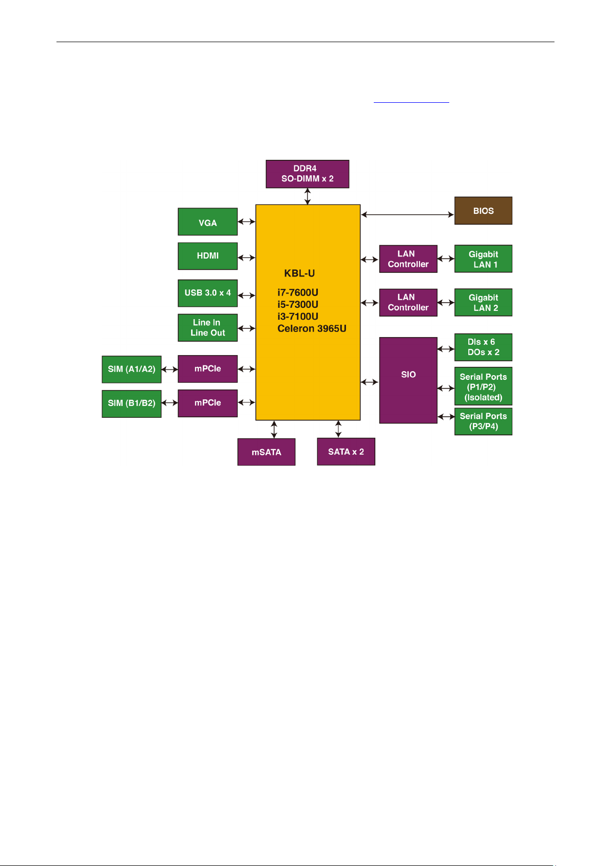
The V2406C Series embedded computers are based on the Intel® 7th generation processor and feature 4
RS-232/422/485 serial ports, dual LAN ports, and 4 USB 3.0 hosts. In addition, the computers provide 1 VGA
output and 1 HDMI display with 4k resolution support. The computers comply with the EN 50155:2017
specifications covering operating temperature, power input voltage, surge, ESD, and vibration, making them
suitable for a variety of industrial applications.
The mSATA socket, SATA connectors, and USB sockets provide the V2406C computers with the reliability
needed for industrial applications that require data buffering and storage expansion. The computers also come
with 2 hot-swappable storage trays for inserting additional storage media, such as hard disk or solid-state
drives, and support hot swapping for convenient, fast, and easy storage replacement. Each storage tray has its
own LED to indicate whether or not a storage module is plugged in.
Package Checklist
The following items are included in the package.
• V2406C embedded computer
• Wall-mounting kit
• 2 HDD trays
• 8 screws for hot-swappable HDD trays
• HDMI cable locker
• Quick installation guide (printed)
• Warranty card
NOTE: Please notify your sales representative if any of the above items are missing or damaged.
Product Features
• Intel® Celeron®/Intel® Core™ i3/i5/i7 high performance network video recorder for rolling stock
applications
• Two hot-swappable trays for 2.5-inch HDD/SSD storage expansion
• API library for easy deployment and storage volume notification
• 4K resolution HDMI display
• 2 Gigabit Ethernet ports with M12 X-coded push-pull connectors
• M12 A-coded power connector
• Compliance with EN 50155:2017 and EN 50121-4 standards
• IEC 61373 certification for shock and vibration resistance
• -40 to 70°C wide temperature models available
*This product is suitable for rolling stock railway applications, as defined by the EN 50155 standard. For a more
detailed statement, click here: www.moxa.com/doc/specs/EN_50155_Compliance.pdf
Page 7
V2406C Hardware Introduction
1-3
Hardware Specifications
For the product hardware specifications, refer to Moxa’s website: https://moxa.com.
Hardware Block Diagram
Page 8

2
2. Hardware Introduction
V2406C embedded computers are compact and rugged for use in industrial applications. LED indicators help
you monitor performance and identify trouble spots, multiple serial ports allow you to connect a variety of
devices for wireless operation, and the reliable and stable hardware platform lets you devote your attention to
developing your applications, rather than diddling with low-level APIs and device drivers.
The following topics are covered in this chapter:
Appearance
Dimensions
LED Indicators
Real-time Clock
Page 9
V2406C Hardware Hardware Introduction
2-2
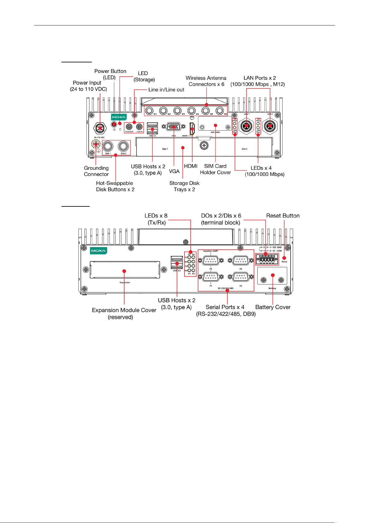
Appearance
Front View
Rear View
Page 10
V2406C Hardware Hardware Introduction
2-3
Yellow
Rx: Receiving Data
her the mSATA or the SATA
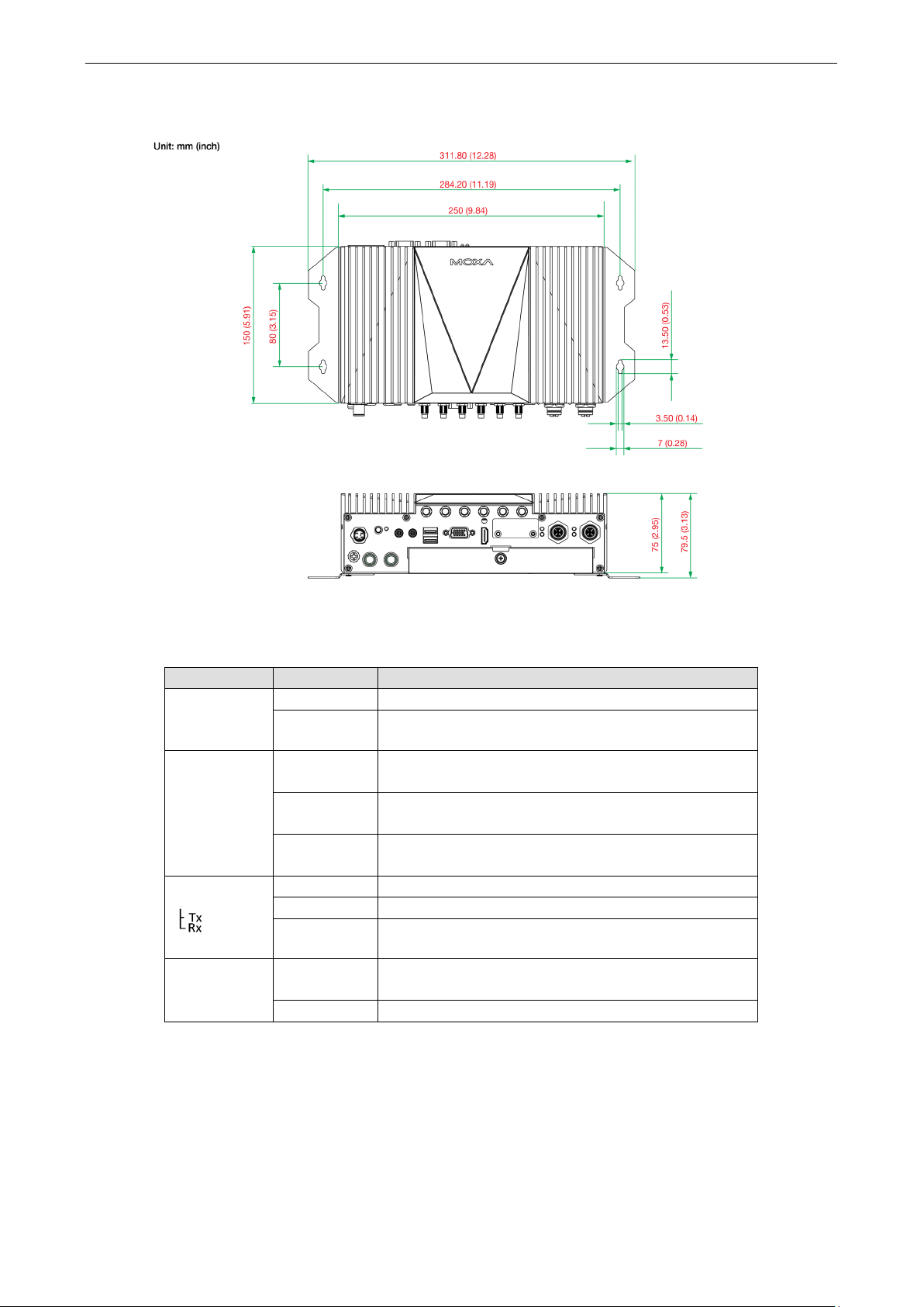
Dimensions
LED Indicators
LED Name Status Function
Power
(on Power
Button)
Ethernet
(100 Mbps)
(1000 Mbps)
Serial
Storage Yellow Data is being accessed from eit
Green Power is on
Off No power input
Green Steady On: 100 Mbps Ethernet link
Yellow Steady On: 1000 Mbps Ethernet link
Off Data transmission speed at 10 Mbps or the cable is not
Green Tx: Data transmission is in progress
Off No operation
Off Data is not being accessed from the storage drives
Blinking: Data transmission is in progress
Blinking: Data transmission is in progress
connected
drive
Page 11

V2406C Hardware Hardware Introduction
2-4
ATTENTION
There is a risk of explosion if the wrong type of battery is used. To avoid this potential danger, always be sure
to use the correc
Caution
Dispose of used batteries
batteries.
Real-time Clock
The embedded computer’s real-time clock is powered by a lithium battery. We strongly recommend that you
NOT replace the lithium battery on your own. If the battery needs to be changed, contact the Moxa RMA service
team.
t type of battery. Contact the Moxa RMA service team if you need to replace your battery.
in a suitable manner. Consult the battery manufacturer for details on disposing
Page 12

3
3. Hardware Connection Description
In this chapter, we show how to connect the embedded computers to the network and to a variety of common
devices.
The following topics are covered in this chapter:
Installing the V2406C
Wiring Requirements
Connecting the Power
Grounding the Unit
Connecting Data Transmission Cables
Connecting to the Network
Connecting to a Serial Device
Connecting an Audio Input and Output
Digital Input/Output
Connecting to a VGA Monitor
Connecting to the USB Ports
Installing a Hot-swappable Storage Drive
Installing the SIM Cards
Installing the Wi-Fi Module
Installing the Cellular Module
Installing the Wireless Cables and Antennas
Switching the Wireless Module Socket
Installing the mSATA Drive
Upgrading the Memory
Replacing the Battery
Page 13
V2406C Hardware Hardware Connection Description
3-2
Installing the V2406C
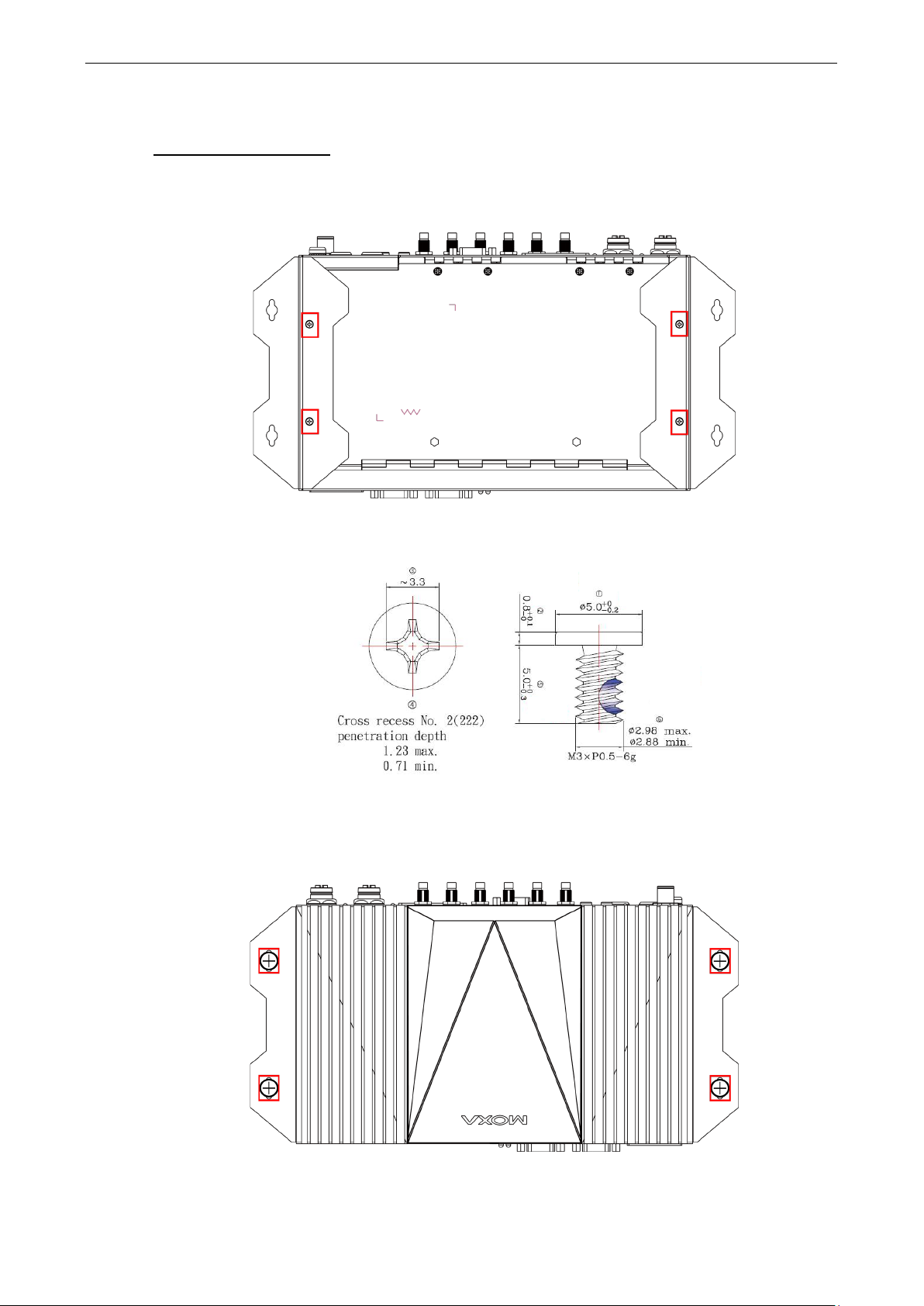
Wall or Cabinet Mounting
The V2406C comes with two wall-mounting brackets. Use two screws per side to attach the mounting bracket
to the computer.
following figure.
The four screws are included in the package. They are standard IMS_M3x5L screws and require a torque of 4.5
kgf-cm. Refer to the following illustration for details.
Ensure that the mounting brackets are attached to the V2406C computer in the direction shown in the
Use two screws (M3*5L standard is recommended) per side to attach the V2406C computer to a wall or a
cabinet. The product package does not include the four screws required for attaching the wall-mounting kit to
the wall; they need to be purchased separately.
the following figure.
Ensure that the V2406C computer is installed in the direction shown in
Page 14
V2406C Hardware Hardware Connection Description
3-3
ATTENTION
Do not run signal or communication wiring together with power wiring in the same wire conduit. To avoid
interference, wires with different signal characteristics should be routed separately.
ATTENTION
Safety First!
Be sure to disconnect the power cord before installing and/or wiring your
Wiring Caution!
Calculate the maximum possible current in each power wire and common wire. Observe all electrical codes
dictating the maximum current allowable for each wire size.
If the current goes above the maximum ratings, the wiring could overheat, causing serious damage to your
equipment.
Temperature Caution!
Be careful when handling the unit. When the unit is plugged in, the internal components generate heat, and
consequently the outer casing may feel hot to the touch.
Wiring Requirements
This section describes how to connect peripheral devices to the embedded computer.
You should read and follow these common safety precautions before proceeding with the installation of any
electronic device:
• Use separate paths to route wiring for power and devices. If power wiring and device wiring paths must
cross, make sure the wires are perpendicular at the intersection point.
• Use the type of signal transmitted through a wire to determine which wires should be kept separate. The
rule of thumb is that wiring that shares similar electrical characteristics can be bundled together.
• Keep input wiring and output wiring separate.
• It is advisable to label the wiring to all devices in the system.
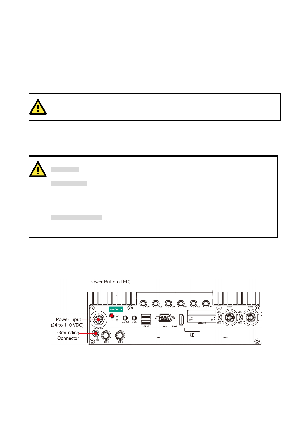
Connecting the Power
Connect the 24 to 110 VDC power line with M12 connector to the V2406C computer. If the power is supplied
properly, the Ready LED will glow a solid green after a 25 to 30 second delay.
V2406C.
Page 15
V2406C Hardware Hardware Connection Description
3-4
ATTENTION
For safety reason, refer to the following instructions on power input installation.
1 or
In addition, a grounding connector is also provided below the power input connector.
Connect the wire to an appropriately grounded metal surface.
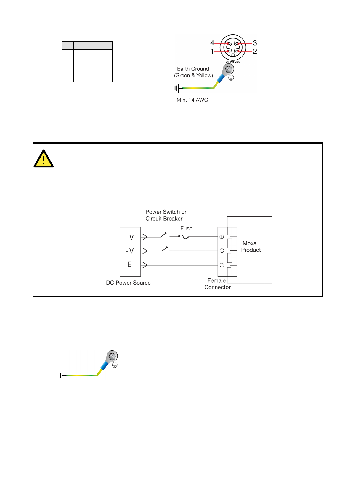
Pin Definition
1 V+
2 N.C.
3 V-
4 N.C.
The power input specification is given below:
• DC mains with a power source rating of 24 V @ 2.74 A; 100 V @ 0.584 A, and a minimum of 14 AWG.
1. The power switch or circuit breaker between Moxa’s products and the power supply should easily
disconnect if a power overcurrent occurs.
2. The maximum branch circuit over current protection rate should be 20 A.
3. The DC power source wire specifications should include minimum 14 AWG and compliance with VW-
FT-1 standards.
For surge protection, connect the grounding connector located below the power connector with the earth
(ground) or a metal surface.
Grounding the Unit
Page 16
V2406C Hardware Hardware Connection Description
3-5
ATTENTION
There is risk of damage to the M12 X
Before you attach an M12 X
The M12
to prevent pin misalignment. Make sure that you
properly
Do NOT insert the cable into a
6
DD-
Connecting Data Transmission Cables
This section describes how to connect V2406C embedded computers to a network and serial devices.
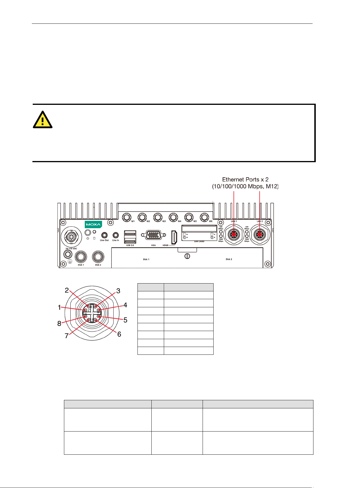
Connecting to the Network
Two 10/100/1000 Mbps Ethernet ports using M12 X-coded connectors are located on the rear panel of the
computer.
X-coded cable is designed with locking mechanisms
align the indicator and notches when connecting the cable.
Refer to the following figure for the specific location of the Ethernet ports.
Refer to the following figure for the pin assignments of the Ethernet ports.
-coded cable to an Ethernet port on the V2406C, read the instructions carefully.
-coded cable due to improper installation or removal.
port with excessive force.
Pin Definition
1 DA+
2 DA-
3 DB+
4 DB-
5 DD+
Follow the steps below to connect an M12 X-coded cable to the computer:
1. Obtain an M12 X-coded cable.
The following table shows the Ethernet connector and cable options. For more information, contact your
local Moxa sales representative.
Model Name Type Description
CBL-M12XMM8PRJ45-BK-100-IP67 Cable and connector 1-meter X-coded M12-to-RJ45 Cat-5E UTP
M12X-8PMM-IP67 Connector Field-installation X-coded screw-in Gigabit
7 DC-
8 DC+
Gigabit Ethernet cable, 8-pin male M12
connector, IP67-rated.
Ethernet connector, 8-pin male, M12
connector, IP67-rated.
Page 17
V2406C Hardware Hardware Connection Description
3-6
NOTE
For best performance and transmission quality, Moxa
recommends that you use cables and connectors
from
NOTE
Do NOT
Phoenix Contact.
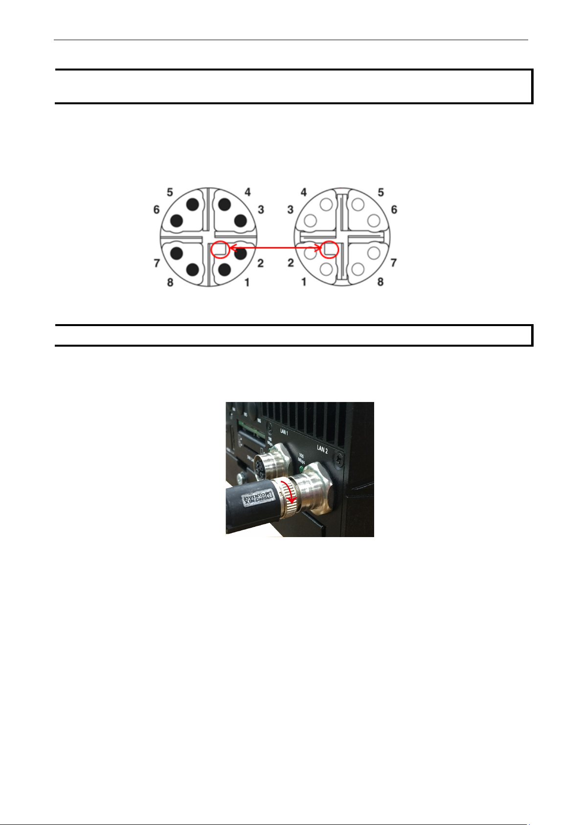
2. Align the notch on the M12 X-coded cable pin core with the notch on the port socket.
Pin assignment of M12 plug. 8-pos.,
X-coded, pin side view
3. Connect the M12 X-coded cable to the port.
4. Turn the interlock screw to tighten it over the cable without using a mechanical tool (such as a screw
use excessive force to push the M12 X-coded cable into the port
wrench).
strongly
M12 socket pin assignment 8-pos,
socket side view
Page 18
V2406C Hardware Hardware Connection Description
3-7
DB9 Male Port
RS
2
RxD
TxDB(+)
TxDB(+)
–
5
GND
GND
GND
GND
NOTE
side
connectors for a
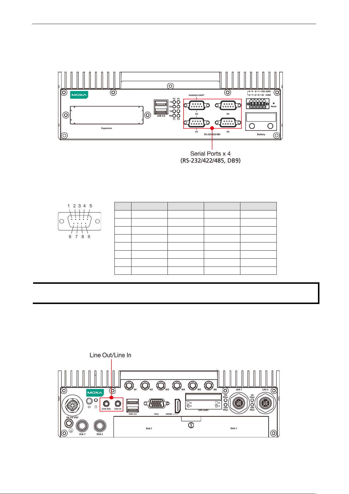
Connecting to a Serial Device
The V2406C comes with four serial ports, which can be configure for RS-232/422/485 interfaces. These ports
are located on the front panel. Port 1 and Port 2 are isolated UART ports.
Use a serial cable to connect your serial device to the embedded computer’s serial port. These ports have male
DB9 connectors and can be configured for RS-232, RS-422, or RS-485 using the software. The pin assignments
of the ports are shown in the table below:
This is the pin assignment for the computer-side connectors on the V2406C. If you are wiring peripheral-
serial cable, you will need to match the pin assignment of the connectors.
-232/422/485 Pinouts
Pin RS-232 RS-422 RS-485-4W RS-485-2W
1 DCD TxDA(-) TxDA(-) –
3 TxD RxDB(+) RxDB(+) DataB(+)
4 DTR RxDA(-) RxDA(-) DataA(-)
6 DSR – – –
7 RTS – – –
8 CTS – – –
Connecting an Audio Input and Output
The V2406C comes with a Line-in and a Line-out with 35 mm jack plug connectors, allowing users to connect
a speaker or an earphone.
Page 19

V2406C Hardware Hardware Connection Description
3-8
NOTE
If
can only be
wired as sink types.
Digital Input/Output
The V2406C comes with a 6-channel digital input and a 2-channel digital output through a terminal block
connector.
Refer to the following figures for the pin definitions and the current ratings.
Digital Inputs
Dry Contact
Logic 0: Short to Ground
Logic 1: Open
Wet Contact (DI to COM)
Logic 1: 10 to 30 VDC
Logic 0: 0 to 3 VDC
Digital Outputs
Current Rating: 200 mA per channel
Voltage: 24 to 30 VDC
The wiring methods are shown in the diagram below:
you are using wet contacts, you must connect the source to power. In addition, both DI and DO
Page 20

V2406C Hardware Hardware Connection Description
3-9
6
GND
14
VSYNC
NOTE
In order to have a highly reliable video streaming capability, choose HDMI
Connecting to a VGA Monitor
The V2406C comes with a D-Sub 15-pin female connector on the rear panel to connect a VGA monitor. To
ensure that the monitor image remains clear, tighten the monitor cable after connecting it to the V2406C. The
pin assignments of the video output connector are shown in the diagram below:
DB15 Female Connector
Pin No. Signal Definition Pin No. Signal Definition
1 Red 9 VCC
2 Green 10 GND
3 Blue 11 NC
4 NC 12 DDC2B Data
5 GND 13 HSYNC
7 GND 15 DDC2B Clock
8 GND
In addition, an HDMI connector is also provided on the rear panel, allowing users to connect another display
with an HDMI interface.
Connecting to the USB Ports
The V2406C comes with four USB ports, two on the front panel, another two on the rear panel. All four ports
come with USB 3.0 type A interfaces. Refer to the following illustrations for the location of these ports.
-certified HDMI cables.
Page 21

V2406C Hardware Hardware Connection Description
3-10
the slot.
You can use these USB ports to connect various peripheral devices, such as a keyboard, a mouse, and USB
storage disks, to your computer.
Installing a Hot-swappable Storage Drive
The V2406C comes with two storage sockets, allowing users to install two disks for data storage.
Follow these steps to install a hard disk drive.
1. Unpack the storage disk tray. 2. Place the disk drive on the tray.
3. Turn the tray and disk arrangement around
so that the back side of the tray is facing
you. Fasten the four screws to secure the
disk to the tray
4. Unfasten the screw on the storage slot
cover and pull down the cover to access
5. Find the location of the storage tray rail
inside the socket.
Page 22

V2406C Hardware Hardware Connection Description
3-11
6. Align the tray with the rail and insert the tray into the socket.
To take out the tray, pull the clutch in the tray to your right and pull out the tray.
Installing the SIM Cards
The V2406C comes with 2 sockets, allowing users to install Wi-Fi or cellular modules. To install the cellular
module, you need to install the SIM card first. Follow these steps.
1. Find the SIM card holder cover on the front panel.
2. Unfasten the two screws on the cover and remove the cover.
Each cellular module supports dual SIM cards and microSIM card type is also supported. Check the following
diagram for the location of the SIM card slots.
3. Check the illustration icon on the panel next to the slots and insert the SIM card(s) in the correct direction.
Page 23

V2406C Hardware Hardware Connection Description
3-12
Inserting the SIM cards incorrectly may damage the slot and the SIM card. Check the following diagrams to
confirm that the SIM card is inserted correctly into the slots.
Module A1 Module A2
Module B1 Module B2
To remove the SIM card, simply push in the SIM card to release it and pull out the SIM card.
4. Replace the cover on the SIM card slot.
Installing the Wi-Fi Module
Follow these steps to install the Wi-Fi Module.
1. Remove the wall-mounting kit brackets.
Page 24

V2406C Hardware Hardware Connection Description
3-13
2. Remove the four screws on the bottom panel of the computer.
3. Remove the screw on storage slot cover on the front panel.
4. Take out the bottom cover of the computer, and find the location of the Wi-Fi module sockets.
There are two sockets; you can install your Wi-Fi module on either one.
5. Check the Wi-Fi module package contents.
Page 25

V2406C Hardware Hardware Connection Description
3-14
7.
6. Install the metal plate and secure it with the two screws in the package.
Place the Wi-Fi module in the socket and
connect the antenna cables to the
connectors.
8. Place the protection cover on the antenna cable
connectors and secure the cover with the two
screws in the package.
Installing the Cellular Module
Follow these steps to install the cellular module on the computer.
1. Check the contents of the cellular module package.
2. Insert the module in the socket and secure it with the two screws in the package.
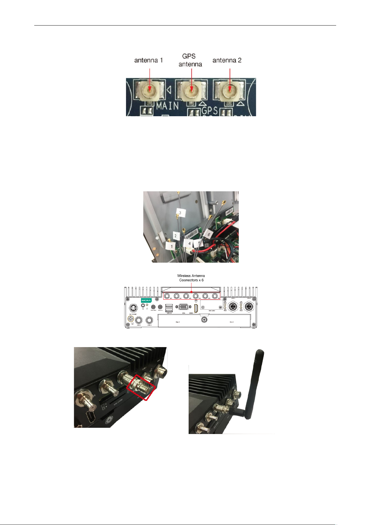
3. Connect the three antenna cables on the connectors.
Page 26
V2406C Hardware Hardware Connection Description
3-15
Note that there are three antenna connectors on the cellular module: one for GPRS and two for cellular
communication.
Installing the Wireless Cables and Antennas
Follow these steps to connect the wireless cables and antennas.
1. Identify the cables inside the computer.
There are six cables for connecting the wireless modules as indicated by the stickers in the following
diagram.
2. Connect the antennas to the correct connectors on the front panel of the computer.
3. There are two methods to connect the antenna.
a. Connect a compatible connector first, and then attach the antenna.
Page 27

V2406C Hardware Hardware Connection Description
3-16
OFF (default)
Cellular
Cellular
DIP switch.
b. Use an extension cord and then connect the antenna.
Switching the Wireless Module Socket
As there are two wireless module sockets and you can install the Wi-Fi or the cellular module on either of the
sockets, a DIP switch is provided to enable selection of the Wi-Fi or cellular module. The DIP switch is located
below the wireless module socket as shown in the following illustration.
Status Socket 1 Socket 2
ON Wi-Fi Wi-Fi
For example, if you install the Wi-Fi module on the
first socket, you need to turn to ON mode on the
Page 28

V2406C Hardware Hardware Connection Description
3-17
Installing the mSATA Drive
There is an mSATA socket inside the computer; users can install the mSATA on their own for storage capacity
expansion. The socket is located beside the wireless module sockets as indicated in the following diagram.
Insert the mSATA module into the socket, and fasten two screws to secure the module.
Upgrading the Memory
The V2406C comes with 2 DDR4 2400 SO-DIMM slots, with 8 GB memory preinstalled on one slot. To upgrade
or replace the memory, follow these steps.
1. Remove the screw on the rear panel and take off the front cover.
An 8-GB memory is preinstalled in the first slot.
Page 29

V2406C Hardware Hardware Connection Description
3-18
2. Push the two clutches on both sides of the memory outwards and remove the memory card.
3. Insert the new memory card, pull in the clutches, and push down the memory card.
Page 30

V2406C Hardware Hardware Connection Description
3-19
Ensure that the memory card in securely inserted.
4. Replace the cover to complete the memory upgrade and installation process.
Replacing the Battery
The V2406C comes with one battery slot containing a lithium battery with the specifications 3V/195 mAh.
To replace the battery, do the following:
1. The battery cover is located on the front panel of the computer.
2. Unfasten the two screws on the battery cover.
3. Remove the cover.
The battery is attached to the cover.
Page 31

V2406C Hardware Hardware Connection Description
3-20
4. Separate the connectors and remove the two screws on the metal plate.
5. Replace the battery, place the metal plate on the battery, and fasten the screws to secure the batteries.
6. Reconnector the connectors, place the battery into the slot, and put back the cover.
7. Secure the cover with the two screws.
Page 32

V2406C Hardware Hardware Connection Description
3-21
NOTE
Make sure you use the correct type of battery. Incorrect battery
technical support staff for assistance
NOTE
This computer is intended to be installed in a restricted access area only. In addition, for safety reasons, the
computer should be installed and handled
NOTE
This computer is designed to be supplied by listed equipment and rated 24 to 110 VDC, minimum 2.74 to 0.584
A, minimal Tma=70˚C. If you need assistance with purchasing a power adapter, contact Moxa
support team.
, if necessary.
only by qualified and experienced professionals.
.
may cause system damage. Contact Moxa’s
technical
Page 33

4
4. BIOS Setup
In this chapter, we describe the V2406C computer’s BIOS settings. The BIOS is a set of input/output control
routines for peripherals. The BIOS is used to initialize basic peripherals and help boot the operating system
before the operating system is loaded. The BIOS setup allows the user to modify the system configurations of
these input/output peripherals. The configuration settings are stored in the CMOS RAM, which receives power
from a backup battery when the computer is not receiving power from an external power source. The system
information is retained even after the system reboots or the power is disconnected.
The following topics are covered in this chapter:
Entering the BIOS Setup
Main Page
Advanced Settings
Boot Configuration
SATA Configuration
Intel Rapid Storage Technology
CPU Configuration
Active Management Technology Support
Video Configuration
Chipset Configuration
SIO ITE8786E
Console Redirection
Security Settings
Current TPM Device
TPM State
Clear TPM
Set Supervisor Password
Power Settings
Wake on LAN
Auto Wake on S5
mPCIE#1 Power
mPCIE#2 Power
Boot Settings
Boot Type
Network Stack
PXE Boot capability
USB Boot
Timeout
EFI
Exit Settings
Exit Saving Changes
Save Change Without Exit
Exit Discarding Changes
Load Optimal Defaults
Load Custom Defaults
Save Custom Defaults
Discard Changes
Enable AMT
Use AMT
Page 34

V2406C Hardware BIOS Setup
4-2
F1
F5/ F6
F9
F10
General Help
Change Values
Setup Defaults
Save and Exi
↑↓
←→
ESC
EN TER
Select Item
Select Menu
Exit
Select or go to Submenu.
Entering the BIOS Setup
To enter the BIOS setup utility, press the F2 key while the system is booting up. The main BIOS Setup screen
will appear. You can configure the following settings on this screen.
• Continue: Continue to boot up
• Boot Manager: Select the device for booting up
• Device Manager:
• Boot From File: Select the UEFI boot up file
• Setup Utility: Enter the BIOS configuration menu
• Intel® Management Engine BIOS Extension: Enter the AMT configuration menu
Select F2 to enter the BIOS configuration.
Enter the device configuration menu
When you enter Setup Utility, a basic description of each function key is listed at the bottom of the screen.
Refer to these descriptions to learn how to use them.
t
.
Page 35

V2406C Hardware BIOS Setup
4-3
The BIOS configuration screen will be shown when you enter the Setup Utility option, as shown in the
following figure:
Note that the Processor Type information will vary depending on the model that you have purchased.
Main Page
The Main page displays basic system hardware information, such as model name, BIOS version, and CPU type.
Page 36

V2406C Hardware BIOS Setup
4-4
NOTE
The
Advanced Settings
Select the Advanced tab in the main menu to open the advanced features screen.
Active Management Technology is not supported in the KL1 and KL3 models.
Page 37

V2406C Hardware BIOS Setup
4-5
Boot Configuration
This item allows users to configure the default value of Numlock.
Options: On (default), Off.
SATA Configuration
You can use this setting to select the mode for the host drive controller. Options are AHCI (default) and Intel
RST Premium.
Page 38

V2406C Hardware BIOS Setup
4-6
Serial ATA Port
This setting displays information on the installed drives.
SATA Port Hot Plug
This setting allows you to enable/disable hot-plugging capabilities (the ability to remove the drive while the
computer is running) for installed storage drives.
Options: Disabled (default for Port 0), Enabled (default for Port 1 and Port 2)
RAID
Set HDC configuration as “Intel RST Premium” to enable redundant array of inexpensive disks technology. The
V2406C has three SATA interfaces, which only supports RAID levels 0, 1, 5 and Recovery.
Recovery utilizes RAID 1 (mirroring) functionality to copy data from a designated master drive to a designated
recovery drive. The master drive data can be copied to the recovery drive either continuously or on request.
When using the continuous update policy, changes made to the data on the master drive while the system is
not docked are automatically copied to the recovery drive when the system is re-docked. When using the on
request update policy, the master drive data can be restored to a previous state by copying the data on the
recovery drive back to the master drive.
Source: http://en.wikipedia.org/wiki/Standard_RAID_levels for details.
Page 39

V2406C Hardware BIOS Setup
4-7
When setting the Intel RST Premium mode, or saving changes and reboot, you can select Device
Management to configure the following Intel Rapid Storage Technology.
Intel Rapid Storage Technology
This section allows users to configure Intel® Rapid Storage Technology.
Page 40

V2406C Hardware BIOS Setup
4-8
NOTE
Hyper-Threading is not supported in the KL1 models.
CPU Configuration
Page 41

V2406C Hardware BIOS Setup
4-9
Active Processor Cores
This item indicates the number of cores to enable in each processor package.
Hyper-Threading
This feature makes the processor resources work more efficiently, enabling multiple threads to run on each
core. It also increases processor throughput, improving overall performance on threaded software.
Options: Disabled, Enabled (default)
Active Management Technology Support
This item allows you to configure the Intel® Active Management Technology (KL1 and KL3 models do not
support this function).
Page 42

V2406C Hardware BIOS Setup
4-10
Unconfigure ME on RTC Clear State
Disabling this option will cause ME not to unconfigure on RTC clear.
Options: Disabled, Enabled (default)
Unconfigure ME
Unconfigure ME by resetting the MEBx password to the default password.
Video Configuration
DVMT Pre-Allocated
This item allows you to configure pre-allocated memory capacity for the IGD. Pre-allocated graphics memory
is invisible to the operating system.
Options: 12 M, 16M, 20M, 24M, 28M, 32M (default), 36M, 40M, 44M, 48M, 52M, 56M, 60M, 64M
DVMT: The amount of video memory your computer has is dependent on the amount of pre-allocated memory
set for your system plus the Dynamic Video Memory Technology (DVMT). DVMT dynamically allocates system
memory for use as video memory creating the most efficient use of available resources for maximum 2D/3D
graphics performance.
DVMT Total Gfx Mem.
This item allows you to configure the maximum amount of memory DVMT will use when allocating additional
memory for the internal graphics device.
Options: 256 MB (default), 128 MB, Max.
Page 43

V2406C Hardware BIOS Setup
4-11
Chipset Configuration
This item allows you to configure the chipset settings.
Power ON after Power Failure
This item allows you to enable/disable the computer from automatically powering up after system power is
re-enabled.
Options: ON (default), OFF, Last State
DO-0 Level
This item allows users to set the DO 0 as high or low.
Options: High (default), Low
DO-1 Level
This item allows users to set the DO 1 as high or low.
Options: High (default), Low
Page 44

V2406C Hardware BIOS Setup
4-12
SIO ITE8786E
This section allows users to configure serial port settings.
Serial Port A
This function allows users to configure the resources for the serial port A.
Disable: No resources
Enable: User configures the resources
Auto (default): EFI/OS chooses the resources
Serial Port B
This function allows users to configure the resources for the serial port B.
Disable: No resources
Enable: User configures the resources
Auto (default): EFI/OS chooses the resources
Serial Port C
This function allows users to configure the resources for the serial port A.
Disable: No resources
Enable: User configures the resources
Auto (default): EFI/OS chooses the resources
Page 45

V2406C Hardware BIOS Setup
4-13
Serial Port D
This function allows users to configure the resources for the serial port A.
Disable: No resources
Enable: User configures the resources
Auto (default): EFI/OS chooses the resources
Hardware Monitor
This item allows you to view stats such as CPU and system temperature, voltage levels, and other chipset
information.
Console Redirection
When the Console Redirection Function is enabled, the console information will be output to both the HDMI
monitor and through the serial port.
Options: Disabled (default), Enabled
Page 46

V2406C Hardware BIOS Setup
4-14
Security Settings
This section allows users to configure security-related settings with a supervisor password and user password.
Current TPM Device
This item shows if the system has TMP device and its type.
TPM State
This item allows you view the status of current TPM settings.
Clear TPM
This item allows users to remove all TPM context associated with a specific owner.
Page 47

V2406C Hardware BIOS Setup
4-15
Set Supervisor Password
This item allows you to set the supervisor password. Select the Set Supervisor Password option and enter
the password and confirm the password again.
To delete the password, select the Set Supervisor Password option and enter the old password; leave the
new password fields blank, and then press enter.
After setting the supervisor password, users can choose when asking input password screen will pop up.
Page 48

V2406C Hardware BIOS Setup
4-16
Enable: System will ask input password on post time.
Disable: System will ask for the password to go to the setup utility.
Config-Only: System will only ask for the password when you select the config (F2) option
Power Settings
The section allows users to configure power settings.
Wake on LAN
This feature is used to wake the system by a LAN device from a remote host.
Options: Enabled (default), Disabled
Auto Wake on S5
This item allows you to configure the computer to wake from S5 status. S5 stands for Soft Off, where the PSU
remains engaged but power to all other parts of the system is cut. Auto-wake on S5 schedules a soft-reboot at
certain periodic times that may be specified in the BIOS.
Options: Disabled (default); By Every Day (user specifies a regular daily time when the computer will power
up); By Day of Month (user specifies a regular day each month when the computer will power up)
mPCIE#1 Power
This item allows you to control the power in the 1st mPCIe connector.
Options: Off (default), on
Page 49

V2406C Hardware BIOS Setup
4-17
NOTE
If you do not add any storage, you will not see the EFI option.
mPCIE#2 Power
This item allows you to control the power in the 2nd mPCIe connector.
Options: Off (default), on
Boot Settings
The section allows users to configure boot settings.
Boot Type
This item allows you to enable/disable the quick boot function.
Options: Dual Boot Type, Legacy Boot Type, UEFI Boot Type (default)
Network Stack
It deploys an Internet Protocol (IP) stack. The IP stack provides an application library to open/close
connections to remote devices and send/receive data between the remote devices.
Options: Disabled (default), Enabled
PXE Boot capability
PXE Booting is booting a system over a network. This item allows users to start PXE over IPv4 or IPv6
Options: Disabled (default), UEFI: IPv4, UEFI: IPv6, UEFI: IPv4/IPv6
Page 50

V2406C Hardware BIOS Setup
4-18
USB Boot
Set booting to USB boot devices capability.
Options: Enabled (Default), Disabled
Timeout
This item allows users to set the number of second that the firmware will wait before booting the original default
boot selection.
EFI
This item allows users to select the boot order. Use F5 (move down) or F6 (move up) to change the value.
Exit Settings
The section allows users to exit the BIOS environment.
Exit Saving Changes
This item allows you to exit the BIOS environment and save the values you have just configured.
Options: Yes (default), No
Save Change Without Exit
This item allows you to save changes without exiting the BIOS environment.
Options: Yes (default), No
Page 51

V2406C Hardware BIOS Setup
4-19
Exit Discarding Changes
This item allows you to exit without saving any changes that might have been made to the BIOS.
Options: Yes (default), No
Load Optimal Defaults
This item allows you to revert to the factory default BIOS values.
Options: Yes (default), No
Load Custom Defaults
This item allows you to load custom default values for the BIOS settings.
Options: Yes (default), No
Save Custom Defaults
This item allows you to save the current BIOS values as a “custom default” that may be reverted to at any time
by the “load custom defaults” selection just above.
Options: Yes (default), No
Discard Changes
This item allows you to discard all settings you have just configured.
Options: Yes (default), No
Page 52

V2406C Hardware BIOS Setup
4-20
NOTE
The AMT function is not supported for KL1 and KL3 models.
Enable AMT
To enter the BIOS setup utility, press the “F2” key while the system is booting up. The main BIOS Setup
screen will appear. Five options will be available:
1. Select Intel® Management Engine BIOS Extension to enter the AMT configuration.
2. Press <Enter> to start the login procedure.
Page 53

V2406C Hardware BIOS Setup
4-21
3. Type the default password: admin
4. Type the new password. It must include both upper-case and lower-case characters, numbers, and special
symbols. E.g., Admin’12.
5. Select Intel® AMT Configuration to enable remote access without a local user present for consent, select
User Consent, and then select User Opt-in and change the value to None.
Page 54

V2406C Hardware BIOS Setup
4-22
6. Set static IP or DHCP by request.
7. Set Activate Network Access to enable remote access capability.
Page 55

V2406C Hardware BIOS Setup
4-23
NOTE
The
NOTE
Refer to the Intel AMT Implementation and Reference Guide for details:
https://software.intel.com/sites/manageability/AMT_Implementation_and_Reference_G
default.htm?turl=WordDocuments%2Faccessingintelamtviathewebuiinterface.htm
Use AMT
You can use any of the available AMT tools to execute the remote management function. The easiest method
is using a web browser.
1. Type the IP for your V2406C that was configured in the AMT configuration with port 16992. The AMT logon
screen will appear.
2. Click on “Log On” and type the username (admin) and password to log in and control the V2406C remotely.
V2406C’s AMT port is LAN1.
uide/
Page 56

V2406C Hardware BIOS Setup
4-24
Upgrading the BIOS
This section describes how to upgrade the BIOS. However, note that it is easy to permanently damage the
computer when upgrading the BIOS. We strongly recommend that you contact Moxa’s technical support staff
for assistance in order to obtain all the necessary tools and the most current advice before attempting to
upgrade the BIOS on any Moxa device.
Step 1: Create a Bootable USB Disk
Before upgrading the BIOS, every user should first create a bootable USB drive as a system boot device.
1. Search “format”, then select Create and format hard disk partitions.
Page 57

V2406C Hardware BIOS Setup
4-25
2. Right click on the USB disk then select “Format”.
3. Select “FAT32”, and click OK to start formatting.
Step 2: Prepare the Upgrade File
You must use the BIOS upgrade installation file to upgrade the BIOS. Contact Moxa’s technical department for
assistance.
1. Get the BIOS upgrade file; it includes an efi folder and a file xxxx.efi.
2. Copy efi folder and xxxx.efi file to the Bootable USB Disk.
Page 58

V2406C Hardware BIOS Setup
4-26
Step 3: Run the upgrade program on the Computer
1. Reboot the computer, and press F2 while booting up to go to the Boot Manager. If BIOS cannot recognize
the USB drive as the boot devices, the USB drive could have no partition table. Use windows command line
tool diskpart to rebuild the partition table.
2. Select the USB Disk
3. Screen will switch to the SHELL environment, type fs0: then, go to the directory where the upgrade file is
located, and type xxxxxx.efi (the name is based on the upgrade file you get from Moxa).
4. The upgrade program will run automatically. Wait patiently until the procedure is finished.
Page 59

V2406C Hardware BIOS Setup
4-27
ATTENTION
Do NOT switch off the power supply during the BIOS upgrade, since doing so may cause the system to crash.
5. When the upgrade is finished, the computer will automatically reboot. You may check BIOS version on the
Main page
6. If the system has more than one boot device, you will see more than one fsx (x represents the number).
7. Go each fsx (x means number), then type ls to view the content of the boot device. If find the upgrade file,
execute it
Page 60

This device complies with part 15 of the FCC Rules. Operation is subject to the following
two conditions: (1) This device may not cause harmful interference, and (2) this device
must accept any interference received, including interference that may cause undesired
operation.
European Community
A
A. Regulatory Approval Statement
Class A: FCC Warning! This equipment has been tested and found to comply with the limits for a Class A digital
device, pursuant to part 15 of the FCC Rules. These limits are designed to provide reasonable protection
against harmful interference when the equipment is operated in a commercial environment. This equipment
generates, uses, and can radiate radio frequency energy and, if not installed and used in accordance with the
instruction manual, may cause harmful interference to radio communications. Operation of this equipment in
a residential area is likely to cause harmful interference in which case the user will be required to correct the
interference at his own expense.
Warning:
This is a class A product. In a domestic environment this product may cause radio interference in which case
the user may be required to take adequate measures.
 Loading...