

Page 1

V2201 Series Linux Software User’s Manual
Version 2.0, November 2020
www.moxa.com/product
© 2020 Moxa Inc. All rights reserved.
Page 2

V2201 Series Linux Software User’s Manual
Moxa Americas
Toll
Tel:
Fax:
Moxa China (Shanghai office)
Toll
Tel:
Fax:
Moxa Europe
Tel:
Fax
Moxa Asia
Tel:
Fax:
Moxa India
Tel:
Fax:
The software described in this manual is furnished under a license agreement and may be used only in accordance with
the terms of that agreement.
Copyright Notice
© 2020 Moxa Inc. All rights reserved.
Trademarks
The MOXA logo is a registered trademark of Moxa Inc.
All other trademarks or registered marks in this manual belong to their respective manufacturers.
Disclaimer
Information in this document is subject to change without notice and does not represent a commitment on the part of
Moxa.
Moxa provides this document as is, without warranty of any kind, either expressed or implied, including, but not limited
to, its particular purpose. Moxa reserves the right to make improvements and/or changes to this manual, or to the
products and/or the programs described in this manual, at any time.
Information provided in this manual is intended to be accurate and reliable. However, Moxa assumes no responsibility for
its use, or for any infringements on the rights of third parties that may result from its use.
This product might include unintentional technical or typographical errors. Changes are periodically made to the
information herein to correct such errors, and these changes are incorporated into new editions of the publication.
Technical Support Contact Information
www.moxa.com/support
-free: 1-888-669-2872
+1-714-528-6777
+1-714-528-6778
+49-89-3 70 03 99-0
: +49-89-3 70 03 99-99
+91-80-4172-9088
+91-80-4132-1045
-free: 800-820-5036
+86-21-5258-9955
+86-21-5258-5505
+886-2-8919-1230
-Pacific
+886-2-8919-1231
Page 3

Table of Contents
1. Introduction ...................................................................................................................................... 1-1
Software Specifications........................................................................................................................ 1-2
2. Software Configuration ..................................................................................................................... 2-1
Account Management .......................................................................................................................... 2-2
Starting From an HDMI Console ............................................................................................................ 2-3
Connecting From an SSH Console ......................................................................................................... 2-3
Windows Users ........................................................................................................................... 2-4
Linux Users ................................................................................................................................ 2-5
Adjusting the System Time .................................................................................................................. 2-5
Setting the Time Manually ............................................................................................................ 2-5
Using the NTP Client and the systemd-timesyncd Service ................................................................. 2-6
Managing the Service Using the systemd Script............................................................................... 2-6
Cron Daemon for Executing Scheduled Commands ................................................................................. 2-8
Mounting an USB Storage Device .......................................................................................................... 2-8
Checking the Linux Version .................................................................................................................. 2-9
APT—Installing and Removing Packages .............................................................................................. 2-10
3. Managing Communications ............................................................................................................... 3-1
Detecting Network Interfaces ............................................................................................................... 3-2
Changing the Network Settings ............................................................................................................ 3-2
Changing the interfaces Configuration File ...................................................................................... 3-2
Adjusting the IP Addresses Using ifconfig ....................................................................................... 3-3
DNS Client ......................................................................................................................................... 3-4
/etc/resolv.conf ........................................................................................................................... 3-4
/etc/nsswitch.conf ....................................................................................................................... 3-4
Configuring the Cellular Connection ...................................................................................................... 3-5
Using cell_mgmt ......................................................................................................................... 3-5
Dial-up Process ........................................................................................................................... 3-7
Dial-up Commands ...................................................................................................................... 3-7
Cellular Module ........................................................................................................................... 3-9
GPS ......................................................................................................................................... 3-12
Configuring the Wi-Fi Connection ........................................................................................................ 3-12
Configuring WPA2 ...................................................................................................................... 3-12
4. System Recovery ............................................................................................................................... 4-1
Recovery Environment ........................................................................................................................ 4-2
Restoring the System From the USB Drive ............................................................................................. 4-2
5. Additional Settings ............................................................................................................................ 5-1
Getting the Product Serial Number ........................................................................................................ 5-2
RTC (Real-time Clock) ......................................................................................................................... 5-2
Serial Ports ........................................................................................................................................ 5-2
Digital I/O.......................................................................................................................................... 5-3
WDT (Watchdog Timer) ....................................................................................................................... 5-3
How the WDT Works .................................................................................................................... 5-3
Page 4

1
1. Introduction
Thank you for purchasing a Moxa V2201 x86 ready-to-run Linux-based embedded computer (V2201-LX). This
manual introduces the software configuration and management of the computer, which runs on the Linux
operating system.
Linux is an open, scalable operating system that allows you to build a wide range of innovative, small-footprint
devices. Software written for desktop PCs can be easily ported to the embedded computer with a GNU cross
compiler and minimum source code modifications. A typical Linux-based device is designed for a specific use,
and is often not connected to other computers, or a number of such devices connect to a centralized, front-end
host.
The following topics are covered in this chapter:
Software Specifications
Page 5
V2201 Series Linux UM Introduction
1-2
NOTE
For information and documentation on Debian GNU/Linux and the free software concept, refer to the following
links:
http://www.debian.org/
http://www.gnu.org/
ATTENTION
The
revision
Software Specifications
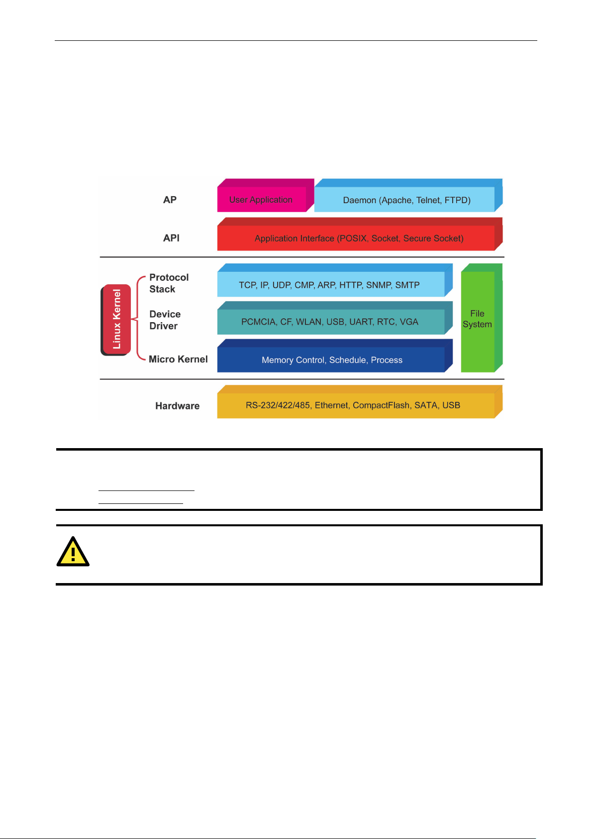
The Linux operating system preinstalled on the V2201-LX is the Debian Stretch 9.12 distribution. The Debian
project is a worldwide group of volunteers who endeavor to produce an operating system distribution that is
composed entirely of free software. The Debian GNU/Linux follows the standard Linux architecture, making it
easy to use programs that meet the POSIX standard. Program porting can be done with the GNU toolchain
provided by Moxa. In addition to Standard POSIX APIs, device drivers for Moxa UART and other special
peripherals are also included. An example software architecture is shown below:
software architecture presented above is only an example. Different product models or different build
s of the Linux operating system may include components not shown here.
Page 6

2
2. Software Configuration
In this chapter, we explain how to operate the V2201-LX directly from your desktop. You can connect to your
embedded computer: using a HDMI display or via SSH over a network console from a Windows or Linux
machine. This chapter describes basic Linux operating system configurations. Advanced network management
and configuration instructions are described in the "3 Managing Communications" chapter.
The following topics are covered in this chapter:
Account Management
Starting From an HDMI Console
Connecting From an SSH Console
Windows Users
Linux Users
Adjusting the System Time
Setting the Time Manually
Using the NTP Client and the systemd-timesyncd Service
Managing the Service Using the systemd Script
Cron Daemon for Executing Scheduled Commands
Mounting an USB Storage Device
Checking the Linux Version
APT—Installing and Removing Packages
Page 7

V2201 Series Linux UM Software Configuration
2-2
Using username "moxa".
higher security level or disable
moxa@Moxa:~$
moxa@Moxa:~$ sudo ifconfig enp1s0 192.168.100.100
device memory 0xb1300000-b137ffff
moxa@Moxa:~# sudo -i
root@Moxa:~$
Account Management
Connect the embedded computer to a display and turn on the computer. Enter the following information to log
in into the computer.
Login: moxa
Password: moxa
For enhanced security, we have disabled the root account. We strongly recommend that you change the
password after the first login. After successfully logging in, provide a new password.
Linux Moxa 4.9.0-6-amd64 #1 SMP Debian 4.9.88-1 (2018-04-29) x86_64
#### #### ###### ####### ###### ##
### #### ### ### #### #### ###
### ### ### ### ### ## ###
### #### ## ## ### # ####
#### # ## ### ### ### ## ## ##
## ## # ## ### ## #### # ##
## ### ## ## ## ## #### # ###
## ## # ## ## ## ### #######
## ## # ## ### ### ##### # ##
## ### ## ### ### ## ### # ###
## ### ## ## ## ## ### ## ##
## ### ## ## ## # ### # ##
###### # ###### ######## ####### ########### ######
For further information check:
http://www.moxa.com/
You have mail.
Last login: Wed Mar 6 00:10:56 2019 from 10.144.54.91
You are using Moxa embedded computer.
Please change the default password in consideration of
the default user, moxa.
After you change the default password, remember to type sudo each time you want to run commands with the
privilege of a root account. For example, typing
to configure the IP address of the LAN 1 port.
moxa@Moxa:~$ sudo ifconfig enp1s0
enp1s0: flags=4099<UP,BROADCAST,MULTICAST> mtu 1500
inet 192.168.100.100 netmask 255.255.255.0 broadcast 192.168.100.255
ether 00:90:e8:00:d7:38 txqueuelen 1000 (Ethernet)
RX packets 0 bytes 0 (0.0 B)
RX errors 0 dropped 0 overruns 0 frame 0
TX packets 0 bytes 0 (0.0 B)
TX errors 0 dropped 0 overruns 0 carrier 0 collisions 0
Use sudo –i to login as the root user to have more privileges.
[sudo] password for moxa:
sudo ifconfig enp1s0 192.168.100.100 will allow you
Page 8

V2201 Series Linux UM Software Configuration
2-3
Moxa login: moxa
moxa@Moxa:~$
LAN 2
192.168.4.127
255.255.255.0
Starting From an HDMI Console
Connect a display to the HDMI connector of the V2201-LX and power it up by connecting the power adapter.
The system will take 30 to 60 seconds to boot up. Once the system is ready, a login screen is displayed.
Enter the login name and password. The default values are both moxa.
Login: moxa
Password: moxa
Password:
#### #### ###### ####### ###### ##
### #### ### ### #### #### ###
### ### ### ### ### ## ###
### #### ## ## ### # ####
#### # ## ### ### ### ## ## ##
## ## # ## ### ## #### # ##
## ### ## ## ## ## #### # ###
## ## # ## ## ## ### #######
## ## # ## ### ### ##### # ##
## ### ## ### ### ## ### # ###
## ### ## ## ## ## ### ## ##
## ### ## ## ## # ### # ##
###### # ###### ######## ###### ########## ######
For further information check:
http://www.moxa.com/
Connecting From an SSH Console
The V2201-LX supports the SSH console to offer better network security compared to Telnet. The default IP
addresses and netmasks of the network interfaces are as follows:
Default IP Address Netmask
LAN 1 192.168.3.127 255.255.255.0
Before using an SSH client on your development PC, you should change the IP address of the PC so that the
network ports are in the same subnet as the IP address of the LAN ports that you will connect to. For example,
if you will connect to LAN1, you could set your PC’s IP address to 192.168.3.126, and the netmask to
255.255.255.0. If you will connect to LAN2, set your PC’s IP address to 192.168.4.126, and the netmask to
255.255.255.0.
Use a cross-over Ethernet cable to connect your development PC directly to the target embedded computer, or
use a straight-through Ethernet cable to connect the computer to a LAN hub or switch. Next, use a SSH client
on your development PC to connect to the target computer. After a connection has been established, type the
login name and password as requested to log in into the computer. The default values are both moxa.
Login: moxa
Password: moxa
Page 9
V2201 Series Linux UM Software Configuration
2-4
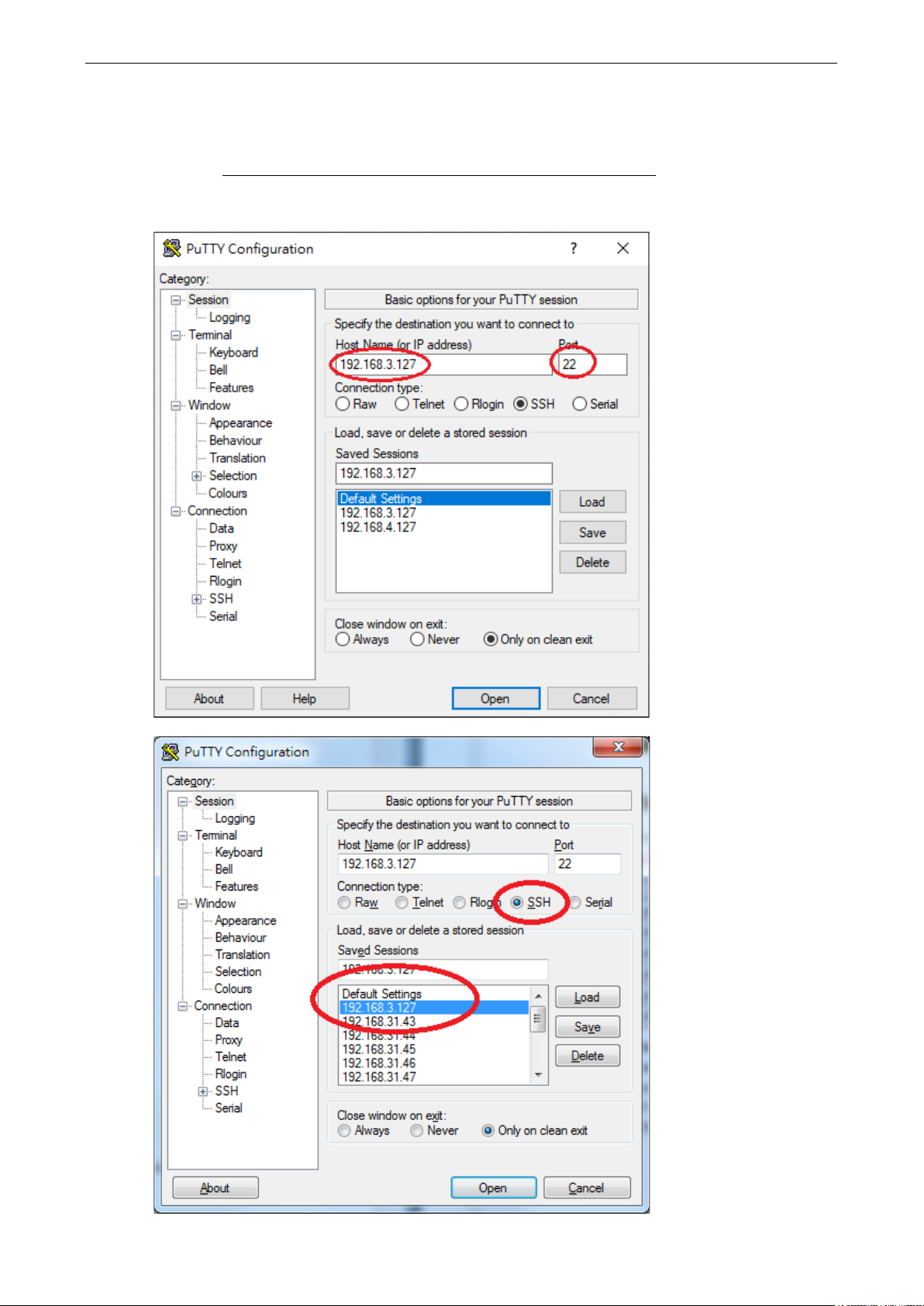
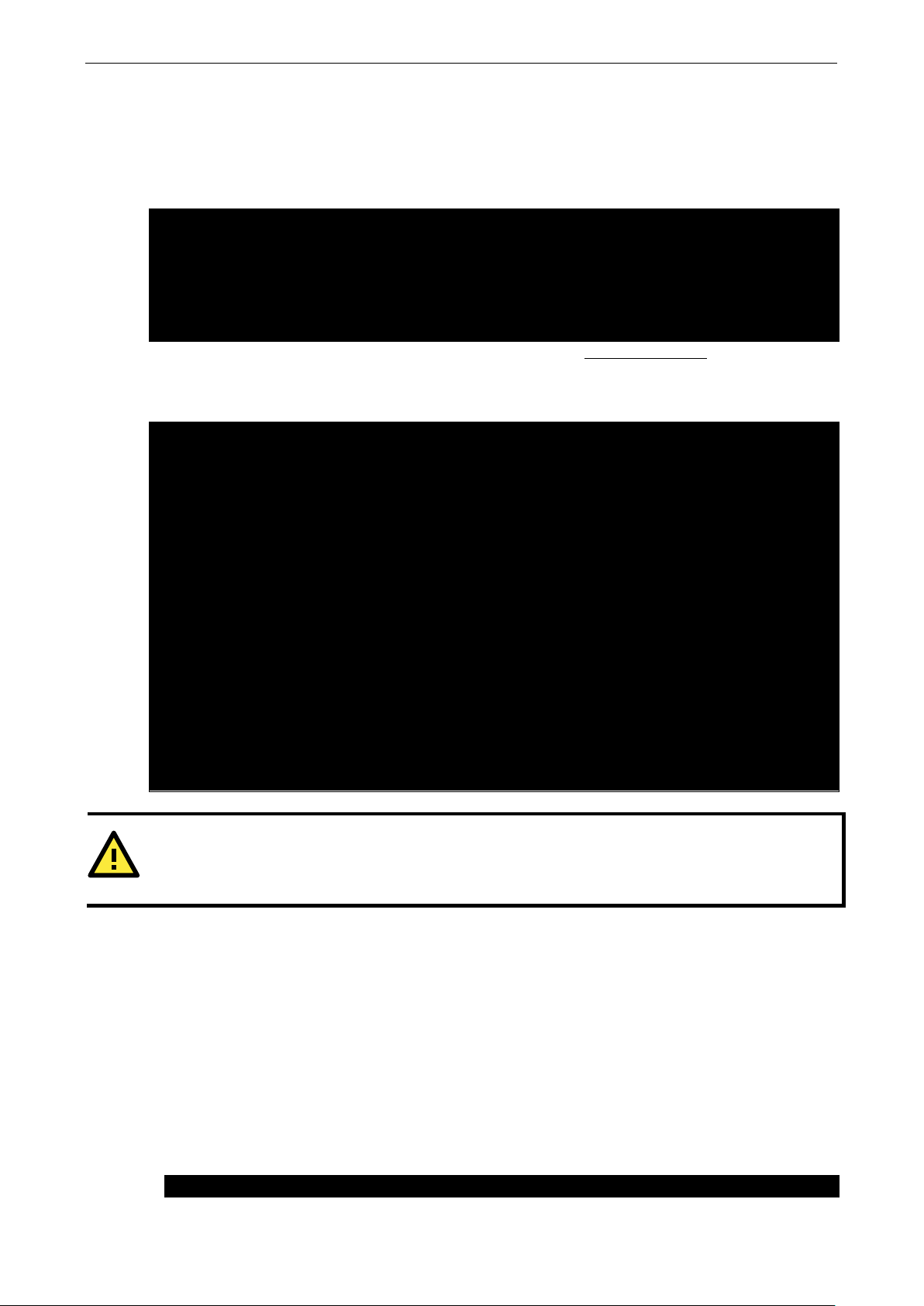
Windows Users
Download the PuTTY tool to set up an SSH console on your development PC. The tool can be downloaded free
of cost at: http://www.chiark.greenend.org.uk/~sgtatham/putty/download.html
The following screens show an example of the configuration settings required to set up an SSH connection.
Page 10

V2201 Series Linux UM Software Configuration
2-5
# ssh moxa@192.168.3.127
[moxa@Moxa:~$]# ssh moxa@192.168.3.127
Are you sure you want to continue connection (yes/no)? yes_
root@Moxa:/home/moxa# date
2019-03-06 19:35:34.061120+0800
Linux Users
From a Linux PC, use the ssh command to access the embedded computer’s console utility via the SSH.
Type yes to open the connection.
The authenticity of host ‘192.168.3.127 (192.168.3.127)’ can’t be established.
RSA key fingerprint is 8b:ee:ff:84:41:25:fc:cd:2a:f2:92:8f:cb:1f:6b:2f.
Adjusting the System Time
The V2201-LX has two time settings; the system time and the real-time clock (RTC) built into the hardware.
Setting the Time Manually
Use the date command to query the current system time or set a new system time. Use the hwclock
command to query the current RTC time or set a new RTC time.
Use the following command to set the system time.
moxa@Moxa:~# date MMDDhhmmYYYY
MM: Month
DD: Date
hhmm: Hour and Minute
YYYY: Year
Use the following command to write the current system time to the RTC.
# hwclock
Wed Mar 6 19:33:51 CST 2019
root@Moxa:/home/moxa# hwclock
2019-03-06 19:33:57.482903+0800
root@Moxa:/home/moxa# date 030619352019.30
Wed Mar 6 19:35:30 CST 2019
root@Moxa:/home/moxa# hwclock -w
root@Moxa:/home/moxa# date; hwclock
Wed Mar 6 19:35:34 CST 2019
Page 11
V2201 Series Linux UM Software Configuration
2-6
root@Moxa:/home/moxa# ntpdate time.stdtime.gov.tw
2019-03-06 19:36:50.154796+0800
root@Moxa:/home/moxa# systemctl status systemd-timesyncd
103.18.128.60:123 (2.debian.pool.ntp.org).
ATTENTION
Before using the NTP client utility, check your IP address and network settings (gateway and DNS)
sure an Internet connection is available.
root@Moxa:~# vi /etc/systemd/system/networking-check.service
Using the NTP Client and the systemd-timesyncd Service
The computer can use a NTP (Network Time Protocol) client to initialize a time request to a remote NTP server.
Use the
network before you run the
6 Mar 19:36:21 ntpdate[1172]: adjust time server 118.163.81.61 offset -0.000877 sec
root@Moxa:/home/moxa# hwclock -w
root@Moxa:/home/moxa# date; hwclock
Wed Mar 6 19:36:50 CST 2019
For more information about NTP and the NTP server addresses, visit http://www.ntp.org.
The computer has a built-in system-timesyncd service that is used for network time synchronization. The
service is enabled by default.
systemd-timesyncd.service - Network Time Synchronization
Loaded: loaded (/lib/systemd/system/systemd-timesyncd.service; enabled; vendor
preset: enabled)
Drop-In: /lib/systemd/system/systemd-timesyncd.service.d
└─disable-with-time-daemon.conf
Active: active (running) since Wed 2019-03-06 19:30:32 CST; 7min ago
Docs: man:systemd-timesyncd.service(8)
Main PID: 274 (systemd-timesyn)
Status: "Synchronized to time server 103.18.128.60:123 (2.debian.pool.ntp.org)."
Tasks: 2 (limit: 4915)
CGroup: /system.slice/systemd-timesyncd.service
└─274 /lib/systemd/systemd-timesyncd
Mar 06 19:30:31 Moxa systemd[1]: Starting Network Time Synchronization...
Mar 06 19:30:32 Moxa systemd[1]: Started Network Time Synchronization.
Mar 06 19:31:02 Moxa systemd-timesyncd[274]: Synchronized to time server
ntpdate command to update the system time. Make sure that the device is connected to an Ethernet
ntpdate command.
Managing the Service Using the systemd Script
Linux services can be started or stopped using systemd scripts. The systemctl command is used to enable
or disable a service.
Follow the example below to add or remove a service.
Creating a System Service Unit
This example creates a systemd service unit in /etc/systemd/system/networking-check.service.
Run the following command using the vi editor to create the networking-check.service file.
to make
Page 12

V2201 Series Linux UM Software Configuration
2-7
[Unit]
WantedBy=default.target
moxa@Moxa:~# sudo vi /usr/local/bin/networking-check.sh
done
root@Moxa:~# chmod a+x /usr/local/bin/networking-check.sh
root@Moxa:~# systemctl start networking-check
root@Moxa:~# ps aux|grep networking-check
root 2276 0.0 0.0 12784 980 pts/0 S+ 14:49 0:00 grep networking-check
root@Moxa:~# cat /var/log/networking-check.log
...
root@Moxa:~# systemctl enable networking-check
root@Moxa:~# reboot
Enter the following entries into the file.
After=snmpd.service
[Service]
ExecStart=/usr/local/bin/networking-check.sh
[Install]
• After: Instructs systemd on when the script should be run. In our case the script will run after the
snmpd.service has started.
• ExecStart: Provides a full path to the script
• WantedBy: Specifies the boot target to which the systemd unit should be installed
This is a basic example of a system script. For more information, check the systemd.service script.
1. Create the /usr/local/bin/networking-check.sh script to check the network status.
This example will ping a global DNS server to check if a network is available and write the results into the
/var/log/networking-check.log.
#!/bin/sh
while [ 1 ]; do
date >> /var/log/networking-check.log
ping -q -w 1 8.8.8.8
if [ $? -eq 0 ]; then
echo "Network is available" >> /var/log/networking-check.log
else
echo "Network is not available" >> /var/log/networking-check.log
fi
sleep 1
2. Before we launch the service, we need to make the script executable using the following command:
3. Start the networking-check service.
The networking-check.sh will be launched in the background.
root 2260 0.0 0.0 4288 1500 ? Ss 14:49 0:00 /bin/sh
/usr/local/bin/networking-check.sh
A /var/log/networking-check.log file is also created.
Wed Mar 14 14:49:09 EDT 2018
Network is available
4. You can enable the service at boot time using the following command and by rebooting the system.
Page 13

V2201 Series Linux UM Software Configuration
2-8
root@Moxa:~# systemctl disable networking-check
0-59
0-23
1-31
1-12
0-6 (0 is Sunday)
#minute hour date month week user command
* 8 * * * root /path/to/your/program
#!/bin/sh
exit 0
# chmod 755 fixtime.sh
* 8 * * * root /home/fixtime.sh
root@Moxa:~# dmesg
[ 564.753797] sd 6:0:0:0: [sdb] Assuming drive cache: write through
To disable the service, use the systemctl disable command as follows:
Remember to stop the service to prevent the log file from occupying too much disk space.
Cron Daemon for Executing Scheduled Commands
The Cron daemon will search /etc/crontab for crontab files. It wakes up every minute and checks each
command to see if it should be run within that minute. When executing commands, output is mailed to the
owner of the crontab (or to the user named in the MAILTO environment variable in the crontab files, if such
a user exists).
Modify the file /etc/crontab to set up your scheduled applications. Crontab files have the following format:
minute
(mm)
For example, issue the following command if you want to launch a program at 8:00 hrs every day.
The following example demonstrates how to use Cron to update the system time and RTC time every day at
8:00 hrs.
1. Write a shell script named fixtime.sh with the following content and save it to
hour
(h)
date
(dom)
Month
(mon)
Week
(dow)
User
(user)
Command
(command)
/home/.
ntpdate time.stdtime.gov.tw
hwclock –w
2. Change the mode of fixtime.sh
3. Modify the /etc/crontab file to run fixtime.sh at 8:00 every day.
Add the following line at the end of crontab file.
Mounting an USB Storage Device
The computer doesn’t support auto mounting of USB storage devices automatically; you need to manually
mount the devices. Before mounting the USB storage, check the USB storage name using the
command.
...
[ 564.751226] sd 6:0:0:0: Attached scsi generic sg1 type 0
[ 564.752400] sd 6:0:0:0: [sdb] 3973118 512-byte logical blocks: (2.03 GB/1.89 GiB)
[ 564.753008] sd 6:0:0:0: [sdb] Write Protect is off
[ 564.753013] sd 6:0:0:0: [sdb] Mode Sense: 03 00 00 00
[ 564.753674] sd 6:0:0:0: [sdb] No Caching mode page found
dmesg
Page 14

V2201 Series Linux UM Software Configuration
2-9
[ 564.759333] sdb: sdb1
[ 564.762273] sd 6:0:0:0: [sdb] Attached SCSI removable disk
root@Moxa:~# cat /proc/partitions
8 17 1985535 sdb1
root@Moxa:~# mount
tf8,errors=remount-ro)
root@Moxa:~# mount –t vfat /dev/sdb1 /mnt
...
/dev/sdb1 /mnt vfat defaults 0 0
ATTENTION
Remember to
before you disconnect the USB storage device. If you do not issue the
command, you may lose data.
ATTENTION
Remember to exit the
device. If you stay in
mount process will fail.
If that happens, type
moxa@Moxa:~$ uname -a
Linux Moxa 4.9.0-6-amd64 #1 SMP Debian 4.9.88-1 (2018-04-29) x86_64 GNU/Linux
Or check /proc/partitions.
major minor #blocks name
8 0 7824600 sda
8 1 7823576 sda1
8 16 1986559 sdb
Mount the USB storage partition 1 /dev/sdb1 at /mnt.
...
/dev/sdb1 on /mnt type vfat
(rw,relatime,fmask=0022,dmask=0022,codepage=437,iocharset=ascii,shortname=mixed,u
If you want to automatically mount the USB storage at boot up, you can add the following in /etc/fstab.
LABEL=root / ext4 noatime,errors=remount-ro 0 1
#usbfs /proc/bus/usb usbfs defaults 0 0
run the # sync command
/media/usb0 or /media/usb1 directory when you disconnect the USB storage
the /media/usb0 or /media/usb1 directory, the automatic un
# umount /media/usb0 to unmount the USB device manually.
Checking the Linux Version
The program uname, which stands for “UNIX Name” and is part of the UNIX operating system, prints the name,
version, and other details of the operating system running on the computer. Use the -a option to generate a
response similar to the one shown below:
Page 15

V2201 Series Linux UM Software Configuration
2-10
deb mirror://debian.moxa.com/debian/mirrors stretch main contrib non-free
#deb-src http://security.debian.org/ stretch/updates main contrib non-free
root@Moxa:~# apt-get update
root@Moxa:~#
root@Moxa:~# apt-get install vim
root@Moxa:~#
root@Moxa:~# apt-get remove vim
root@Moxa:~#
root@Moxa:~# apt-get remove vim --purge
root@Moxa:~#
ATTENTION
You can free up the cache space with the
root@Moxa:~# apt-get clean
root@Moxa:~#
APT—Installing and Removing Packages
APT is the Debian tool used to install and remove packages. Before installing a package, you need to configure
the apt source file /etc/apt/sources.list.
1. Use the vi editor to configure /etc/apt/sources.list.
deb http://deb.debian.org/debian stretch main contrib non-free
#deb-src http://deb.debian.org/debian stretch main contrib non-free
deb http://deb.debian.org/debian stretch-updates main contrib non-free
#deb-src http://deb.debian.org/debian stretch-updates main contrib non-free
deb http://deb.debian.org/debian stretch-backports main contrib non-free
#deb-src http://deb.debian.org/debian stretch-backports main contrib non-free
deb http://security.debian.org/ stretch/updates main contrib non-free
2. Update the source list after you configure it.
3. After identifying the package(s) that you want to install (for example, vim), type:
Use one of the following commands to remove a package.
(a) For a simple package removal:
(b) For a complete package removal:
# apt-get clean command.
Page 16

3
3. Managing Communications
The V2201-LX ready-to-run embedded computer is a network-centric platform designed to serve as a front-end
for data acquisition and industrial control applications. This chapter describes how to configure the various
communication functions supported by the Linux operating system.
The following topics are covered in this chapter:
Detecting Network Interfaces
Changing the Network Settings
Changing the interfaces Configuration File
Adjusting the IP Addresses Using ifconfig
DNS Client
/etc/resolv.conf
/etc/nsswitch.conf
Configuring the Cellular Connection
Using cell_mgmt
Dial-up Process
Dial-up Commands
Cellular Module
GPS
Configuring the Wi-Fi Connection
Configuring WPA2
Page 17

V2201 Series Linux UM Managing Communications
3-2
# PCI device 0x10ec:0x8168 (r8168)
=“00:90:e8:00:00:21”,
ATTR{dev_id}==“0x0”, ATTR{type}==“1”, KERNEL==“eth*”, NAME=“eth1”
ATTENTION
When replacing or connecting a network interface,
/etc/udev/rules.d/70
abnormally
/etc/udev/rules.d/70
Default IP Address
Netmask
moxa@Moxa:~# cd /etc/network
moxa@Moxa:/etc/network# vi interfaces
Detecting Network Interfaces
Debian Linux systems use udevd to detect new network interfaces including Ethernet interfaces and wireless
interfaces. Some of the rules used for creating a persistent network interface naming order are
/lib/udev/rules.d/75-persistent-net-generator.rules and
etc/udev/rules.d/70-persistent-net.rules. The content of the later is similar to the following:
SUBSYSTEM==“net”, ACTION==“add”, DRIVERS==“?*”, ATTR{address}==“00:90:e8:00:00:20”,
ATTR{dev_id}==“0x0”, ATTR{type}==“1”, KERNEL==“eth*”, NAME=“eth0”
# PCI device 0x10ec:0x8168 (r8168)
SUBSYSTEM==“net”, ACTION==“add”, DRIVERS==“?*”, ATTR{address}=
The above example indicates that the system has detected two Ethernet interfaces.
. To avoid this problem, delete the contents of the file
-persistent-net.rules, which could cause network interfaces to be detected
-persistent-net.rules and reboot the system.
the system may keep the old record in
Changing the Network Settings
The V2201-LX has two 10/100 or 10/100/1000 Ethernet ports named LAN1 and LAN2. The default IP addresses
and netmasks of these network interfaces are:
LAN1 192.168.3.127 255.255.255.0
LAN2 192.168.4.127 255.255.255.0
These network settings can be modified by changing the interfaces configuration file, or they can be adjusted
temporarily with the
Changing the interfaces Configuration File
1. Type cd /etc/network to change directories.
ifconfig command.
2. Type vi interfaces to edit the network configuration file using the vi editor. You can configure the V2201’s
Ethernet ports for static or dynamic (DHCP) IP addresses.
Page 18

V2201 Series Linux UM Managing Communications
3-3
# The loopback network interface
broadcast 192.168.4.255
# The primary network interface
iface eth0 inet dhcp
moxa@Moxa:~# /etc/init.d/networking restart
moxa@Moxa:~# ifconfig enp1s0 192.168.1.1
moxa@Moxa:~#
Static IP Address
You can modify the default static IP addresses as follows:
auto lo
iface lo inet loopback
# The primary network interface
auto eth0
iface eth0 inet static
address 192.168.3.127
netmask 255.255.255.0
broadcast 192.168.3.255
auto eth1
iface eth1 inet static
address 192.168.4.127
netmask 255.255.255.0
Dynamic IP Address Using DHCP
To configure one or both LAN ports to request an IP address dynamically, replace static with dhcp in the
previous command.
auto eth0
After modifying the boot settings of the LAN interface, issue the following command to immediately activate the
LAN settings.
Adjusting the IP Addresses Using ifconfig
IP settings can be adjusted at runtime, but the new settings will only be saved to the flash ROM if the
/etc/network/interfaces is modified. For example, type the command
to change the IP address of LAN1 to 192.168.1.1.
# ifconfig enp1s0 192.168.1.1
Page 19

V2201 Series Linux UM Managing Communications
3-4
root@Moxa:/etc# cat resolv.conf
Moxa:/etc#
# /etc/nsswitch.conf
netgroup: nis
DNS Client
The V2201-LX supports DNS client (but not the DNS server). To set up a DNS client, you need to edit the
following two configuration files: /etc/resolv.conf and /etc/nsswitch.conf.
/etc/resolv.conf
This is the most important file that you need to edit when using DNS. For example, before using # ntpdate
time.stdtime.gov.tw
Ask your network administrator which DNS server address you should use. The DNS server’s IP address is
specified using the
following to the /etc/resolv.conf file.
nameserver 168.95.1.1
#
# resolv.conf This file is the resolver configuration file
# See resolver(5).
#
#nameserver 192.168.1.16
nameserver 168.95.1.1
nameserver 140.115.1.31
nameserver 140.115.236.10
to update the system time, you will need to add the DNS server address to the file.
nameserver command. For example, if the DNS server’s IP address is 168.95.1.1, add the
/etc/nsswitch.conf
This file defines the sequence of files, /etc/hosts or /etc/resolv.conf, to be read to resolve the IP address.
The
hosts line in /etc/nsswitch.conf means use /etc/host first and the DNS service to resolve the
address.
#
# Example configuration of GNU Name Service Switch functionality.
# If you have the `glibc-doc-reference’ and `info’ packages installed, try:
# `info libc “Name Service Switch”‘ for information about this file.
passwd: compat
group: compat
shadow: compat
hosts: files dns
networks: files
protocols: db files
services: db files
ethers: db files
rpc: db files
Page 20

3-5
NAME
Power cycle the module slot.
V2201 Series Linux UM Managing Communications
Configuring the Cellular Connection
Using cell_mgmt
The cell_mgmt utility is used to manage the cellular module in the computer. You must use sudo to run the
cell_mgmt command or use root permission. The cell_mgmt utility does not support SMS and MMS
communication.
Manual Page
cell_mgmt
USAGE
cell_mgmt [-i <module id>] [options]
OPTIONS
-i <module id>
Module identifier, start from 0 and default to 0.
-s <slot id>
Slot identifier, start from 1 and default value depends
on module interface.
example: module 0 may in slot 2
modules
Shows module numbers supported.
slot
Shows module slot id
interface [interface id]
Switching and checking module interface(s)
start [OPTIONS]
Start network.
OPTIONS:
PIN - PIN code
Phone - Phone number (especially for AT based modules)
Auth - Authentication type(CHAP|PAP|BOTH), default=NONE.
Username
Password
example:
cell_mgmt start
cell_mgmt start PIN=0000
cell_mgmt start PIN=0000 Phone=*99#
cell_mgmt start PIN=0000 Phone=*99# \
Auth=BOTH Username=moxa Password=moxamoxa
stop
network.
power_on
Power ON.
power_off
Power OFF.
power_cycle
Page 21

V2201 Series Linux UM Managing Communications
3-6
switch_sim <1|2>
Cellular management version.
Switch SIM slot.
gps_on
GPS ON.
gps_off
GPS OFF.
attach_status
Query network registration status.
status
Query network connection status.
signal
Get signal strength.
at <'AT_COMMAND'>
Input AT Command.
Must use SINGLE QUOTATION to enclose AT Command.
sim_status
Query sim card status.
unlock_pin <PIN>
Unlock PIN code and save to configuration file.
pin_retries
Get PIN code retry remain times.
pin_protection <enable|disable> <current PIN>
Set PIN protection in the UIM.
set_flight_mode <0|1>
Set module into flight mode (1) or online mode (0).
set_apn <APN>
Set APN to configuration file.
check_carrier
Check current carrier.
switch_carrier <Verizon|ATT|Sprint|Generic>
Switching between US carrier frequency bands.
m_info
Module/SIM information.
module_info
Module information.
module_ids
Get device IDs (ex: IMEI and/or ESN).
iccid
Get SIM card ID
imsi
Get IMSI (International Mobile Subscriber Identity).
location_info
Get cell location information.
operator
Telecommunication operator.
vzwauto
Verizon Private Network auto dialup.
version
Page 22

V2201 Series Linux UM Managing Communications
3-7
moxa@Moxa:/home/moxa$ sudo cell_mgmt sim_status
+CPIN: READY
moxa@Moxa:/home/moxa$ sudo cell_mgmt set_apn internet
old APN=test, new APN=internet
moxa@Moxa:/home/moxa$ sudo cell_mgmt attach_status
PS: attached
moxa@Moxa:/home/moxa$ sudo cell_mgmt start
Network started successfully
moxa@Moxa:/home/moxa$ sudo cell_mgmt stop
Clearing state...
Dial-up Process
Before dialing, ensure that the APN (access point name) is set correctly and the cellular module is attached to
a base station.
1. Unlock the PIN code if the SIM is locked.
Use the
unlock_pin
2. Use the cell_mgmt set_apn <APN> command to set the name of the access point that will be used to
connect to the carrier.
3. Check if the service attaches with the correct APN.
CS: attached
PS (packet-switched) should be attached for a network connection.
cell_mgmt sim_status command to check the SIM card status and the cell_mgmt
<PIN> command to unlock the SIM card if a SIM PIN is set.
4. Dial up using the
cell_mgmt start command.
PIN code: Disabled or verified
Starting network with '_qmicli --wds-start-network=apn=internet,ip-type=4
--client-no-release-cid --device-open-net=net-802-3|net-no-qos-header'...
Saving state... (CID: 8)
Saving state... (PDH: 1205935456)
The dial-up function in the cell_mgmt utility will automatically set the DNS and default gateway of the
computer, if they have not been set.
Dial-up Commands
cell_mgmt start
To start a network connection, use the default cellular module of the computer (If the computer supports
multiple modules, use the
If you run the
be written to the configuration file
This information is then used when you run the command without specifying the options.
cell_mgmt start command with the Username, Password, and PIN, the configuration will
cell_mgmt interface command to verify the default module that is selected).
/etc/moxa-cellular-utils/moxa-cellular-utils.conf.
Usage:
cell_mgmt start Username=[user] Password=[pass] PIN=[pin_code]
cell_mgmt stop
Stops/disables the network connection on the cellular module of the computer
Killed old client process
Stopping network with '_qmicli --wds-stop-network=1205933264 --client-cid=8'...
Network stopped successfully
Page 23

V2201 Series Linux UM Managing Communications
3-8
moxa@Moxa:/home/moxa$ sudo cell_mgmt status
Status: connected
root@Moxa:/home/moxa$ sudo cell_mgmt signal
4G Level 4 (Good)
Level
Description
3
Fair
moxa@Moxa:/home/moxa$ sudo cell_mgmt signal
umts -77 dbm
-105 to -115 dBm
Poor
>-85 dBm
Excellent
moxa@Moxa:/home/moxa$ sudo cell_mgmt operator
Chunghwa
cell_mgmt status
Provides information on the status of the network connection.
cell_mgmt signal
Provides the cellular signal strength. For moxa-cellular-utils version 2.0.0 and later, cellular signal strength is
indicated using levels.
5 Excellent
4 Good
2 Poor
1 Very Poor
0 No Signal
For moxa-cellular-utils versions prior to version 2.0.0, the cellular signal strength is measured using Reference
Signal Received Power (RSRP). The following table lists the signal strength for various RSRP ranges.
RSRP Signal Strength
<-115 dBm No signal
-95 to -105 dBm Fair
-85 to -95 dBm Good
cell_mgmt operator
Provides information on the cellular service provider.
Page 24

V2201 Series Linux UM Managing Communications
3-9
moxa@Moxa:/home/moxa$ sudo cell_mgmt module_info
Modem_port: NotSupport
moxa@Moxa:/home/moxa$ sudo cell_mgmt interface
[0] wwan0 <Current>
moxa@Moxa:/home/moxa$ sudo cell_mgmt power_cycle
[232733.217132] qcserial ttyUSB0: Qualcomm USB modem converter now disconnected from
[232733.256738] qcserial ttyUSB1: Qualcomm USB modem converter now disconnected from
isconnected from
[232747.099156] usb 1-1: Qualcomm USB modem converter now attached to ttyUSB1
Cellular Module
cell_mgmt module_info
Provides information on the cellular module including AT port, GPS port, QMI port, and module name.
SLOT: 1
Module: MC7354
WWAN_node: wwan0
AT_port: /dev/ttyUSB2
GPS_port: /dev/ttyUSB1
QMI_port: /dev/cdc-wdm0
cell_mgmt interface
Used to view the supported modules and default module on the computer with their IDs. Change the default
module by specifying the ID.
cell_mgmt power_cycle
Use the cell_mgmt power_cycle command to power cycle the cellular module in the computer. You may see
a kernel message indicating that the module has been reloaded.
Network already stopped
Clearing state...
[232733.202208] usb 1-1: USB disconnect, device number 2
ttyUSB0
[232733.225616] qcserial 1-1:1.0: device disconnected
ttyUSB1
[232733.265214] qcserial 1-1:1.2: device disconnected
[232733.281566] qcserial ttyUSB2: Qualcomm USB modem converter now d
ttyUSB2
[232733.290006] qcserial 1-1:1.3: device disconnected
[232733.313572] qmi_wwan 1-1:1.8 wwan0: unregister 'qmi_wwan'
usb-musb-hdrc.0.auto-1, WWAN/QMI device
[232746.879873] usb 1-1: new high-speed USB device number 3 using musb-hdrc
[232747.020358] usb 1-1: config 1 has an invalid interface number: 8 but max is 3
[232747.027639] usb 1-1: config 1 has no interface number 1
[232747.036212] usb 1-1: New USB device found, idVendor=1199, idProduct=68c0
[232747.043185] usb 1-1: New USB device strings: Mfr=1, Product=2, SerialNumber=3
[232747.050473] usb 1-1: Product: MC7354
[232747.054151] usb 1-1: Manufacturer: Sierra Wireless, Incorporated
[232747.068022] qcserial 1-1:1.0: Qualcomm USB modem converter detected
[232747.079525] usb 1-1: Qualcomm USB modem converter now attached to ttyUSB0
[232747.089754] qcserial 1-1:1.2: Qualcomm USB modem converter detected
Page 25

V2201 Series Linux UM Managing Communications
3-10
[232747.109317] qcserial 1-1:1.3: Qualcomm USB modem converter detected
usb-musb-hdrc.0.auto-1, WWAN/QMI device, 0a:ba:e1:d6:ed:4a
moxa@Moxa:/home/moxa$ sudo cell_mgmt check_carrier
--------------------------------
moxa@Moxa:/home/moxa$ sudo cell_mgmt switch_carrier
[236362.482562] qcserial ttyUSB0: Qualcomm USB modem converter now disconnected from
tyUSB1: Qualcomm USB modem converter now disconnected from
[236362.544653] qcserial ttyUSB2: Qualcomm USB modem converter now disconnected from
[236376.209868] usb 1-1: new high-speed USB device number 4 using musb-hdrc
[232747.118581] usb 1-1: Qualcomm USB modem converter now attached to ttyUSB2
[232747.130890] qmi_wwan 1-1:1.8: cdc-wdm0: USB WDM device
[232747.137174] qmi_wwan 1-1:1.8 wwan0: register 'qmi_wwan' at
cell_mgmt check_carrier
The cell_mgmt check_carrier command helps to check if the current carrier matches with the service
(SIM card) provider.
----------Carrier Info----------
preferred firmware=05.05.58.01
preferred carrier name=ATT
preferred carrier config=ATT_005.026_000
firmware=05.05.58.01
carrier name=ATT
carrier config=ATT_005.026_000
cell_mgmt switch_carrier
Some modules provide multiple carrier support. Use the cell_mgmt switch_carrier command to switch
between carriers. It may take some time (depending on the module's mechanism) to switch between carriers.
----------------------
Usage:
switch_carrier <Verizon|ATT|Sprint|Generic>
moxa@Moxa:/home/moxa$ sudo cell_mgmt switch_carrier Verizon
----------switch_carrier------------
cmd=AT!GOBIIMPREF="05.05.58.01","VZW","VZW_005.029_001"
OK
OK
wait for power cycle...
Network already stopped
Clearing state...
[236362.468977] usb 1-1: USB disconnect, device number 3
ttyUSB0
[236362.491019] qcserial 1-1:1.0: device disconnected
[236362.521065] qcserial t
ttyUSB1
[236362.529430] qcserial 1-1:1.2: device disconnected
ttyUSB2
[236362.553133] qcserial 1-1:1.3: device disconnected
[236362.558283] qmi_wwan 1-1:1.8 wwan0: unregister 'qmi_wwan'
usb-musb-hdrc.0.auto-1, WWAN/QMI device
Page 26

V2201 Series Linux UM Managing Communications
3-11
[236376.350358] usb 1-1: config 1 has an invalid interface number: 8 but max is 3
[236411.393963] qcserial ttyUSB0: Qualcomm USB modem converter now disconnected from
[236411.446102] qcserial ttyUSB2: Qualcomm USB modem converter now disconnected from
--------------------------------
[236376.357639] usb 1-1: config 1 has no interface number 1
[236376.364991] usb 1-1: New USB device found, idVendor=1199, idProduct=68c0
[236376.371925] usb 1-1: New USB device strings: Mfr=1, Product=2, SerialNumber=3
[236376.379217] usb 1-1: Product: MC7354
[236376.382924] usb 1-1: Manufacturer: Sierra Wireless, Incorporated
[236376.400588] qcserial 1-1:1.0: Qualcomm USB modem converter detected
[236376.412010] usb 1-1: Qualcomm USB modem converter now attached to ttyUSB0
[236376.422273] qcserial 1-1:1.2: Qualcomm USB modem converter detected
[236376.429958] usb 1-1: Qualcomm USB modem converter now attached to ttyUSB1
[236376.441031] qcserial 1-1:1.3: Qualcomm USB modem converter detected
[236376.448337] usb 1-1: Qualcomm USB modem converter now attached to ttyUSB2
[236376.461514] qmi_wwan 1-1:1.8: cdc-wdm0: USB WDM device
[236376.467762] qmi_wwan 1-1:1.8 wwan0: register 'qmi_wwan' at
usb-musb-hdrc.0.auto-1, WWAN/QMI device, 0a:ba:e1:d6:ed:4a
[236411.387228] usb 1-1: USB disconnect, device number 4
ttyUSB0
[236411.402361] qcserial 1-1:1.0: device disconnected
[236411.422719] qcserial ttyUSB1: Qualcomm USB modem converter now disconnected
[236411.431186] qcserial 1-1:1.2: device disconnected
ttyUSB2
[236411.454583] qcserial 1-1:1.3: device disconnected
[236411.459687] qmi_wwan 1-1:1.8 wwan0: unregister 'qmi_wwan'
usb-musb-hdrc.0.auto-1, WWAN/QMI device
[236423.109879] usb 1-1: new high-speed USB device number 5 using musb-hdrc
[236423.250364] usb 1-1: config 1 has an invalid interface number: 8 but max is 3
[236423.257649] usb 1-1: config 1 has no interface number 1
[236423.266064] usb 1-1: New USB device found, idVendor=1199, idProduct=68c0
[236423.273024] usb 1-1: New USB device strings: Mfr=1, Product=2, SerialNumber=3
[236423.280331] usb 1-1: Product: MC7354
[236423.284011] usb 1-1: Manufacturer: Sierra Wireless, Incorporated
[236423.298320] qcserial 1-1:1.0: Qualcomm USB modem converter detected
[236423.310356] usb 1-1: Qualcomm USB modem converter now attached to ttyUSB0
[236423.318614] qcserial 1-1:1.2: Qualcomm USB modem converter detected
[236423.328841] usb 1-1: Qualcomm USB modem converter now attached to ttyUSB1
[236423.338942] qcserial 1-1:1.3: Qualcomm USB modem converter detected
[236423.348418] usb 1-1: Qualcomm USB modem converter now attached to ttyUSB2
[236423.360733] qmi_wwan 1-1:1.8: cdc-wdm0: USB WDM device
[236423.366960] qmi_wwan 1-1:1.8 wwan0: register 'qmi_wwan' at
usb-musb-hdrc.0.auto-1, WWAN/QMI device, 0a:ba:e1:d6:ed:4a
moxa@Moxa:/home/moxa$ sudo cell_mgmt check_carrier
----------Carrier Info----------
preferred firmware=05.05.58.01
preferred carrier name=VZW
preferred carrier config=VZW_005.029_001
firmware=05.05.58.01
carrier name=VZW
carrier config=VZW_005.029_001
Page 27

V2201 Series Linux UM Managing Communications
3-12
moxa@Moxa:/home/moxa$ sudo cell_mgmt at 'AT+CSQ'
OK
root@Moxa:/home/moxa# cell_mgmt gps_on
root@Moxa:/home/moxa# cell_mgmt module_info
AT_port (reserved): NotSupport
root@Moxa:/home/moxa# cat /dev/ttyUSB1
cell_mgmt at AT_command
Used to input an AT command. For example, use the AT command AT+CSQ as follows:
+CSQ: 18,99
GPS
To view the GPS information, do the following:
1. Power on the GPS module.
2. Check the GPS port using the cell_mgmt command.
In the following example, the GPS port is at
SLOT: 1
Module: MC7354
WWAN_node: wwan1
AT_port: /dev/ttyUSB2
GPS_port: /dev/ttyUSB1
QMI_port: /dev/cdc-wdm1
Modem_port: NotSupport
/dev/ttyUSB1.
3. Type the following command to get the GPS location information from the GPS port.
Configuring the Wi-Fi Connection
You can configure the Wi-Fi connection for your x86 computer using a configuration file and the
wpa_supplicant command.
Configuring WPA2
Moxa’s x86 computers support WPA2 security using the /sbin/wpa_supplicant program. Refer to the
following table for the configuration options. The following table specifies whether an encryption and/or
authentication key must be configured before associating with a network.
Page 28

V2201 Series Linux UM Managing Communications
3-13
network?
ESS
Shared
None
Yes
No
Yes
ESS
WPA2-PSK
AES
Yes
Yes
No
ctrl_interface=/var/run/wpa_supplicant
#######################
root@Moxa:~# wpa_supplicant -i <interface> -c <configuration file> -B
Infrastructure
mode
ESS Open None No No No
ESS Open WEP Optional Optional Yes
ESS Shared WEP Optional Optional Yes
ESS WPA WEP No Yes No
ESS WPA TKIP No Yes No
ESS WPA2 AES No Yes No
ESS WPA-PSK WEP Yes Yes No
ESS WPA-PSK TKIP Yes Yes No
Authentication
mode
Configuring Wireless LAN Using the Configuration File
You can create a /etc/wpa_supplicant/wpa_supplicant.conf file to configure a Wi-Fi connection. An
example of a configuration file for an OPEN/WEP/WPA/WPA2 access point is given below:
update_config=1
### Open system ###
#network={
# ssid="Open"
# key_mgmt=NONE
#}
###################
##### WEP #####
#network={
# ssid="WEP-ssid"
# bssid=XX:XX:XX:XX:XX:XX
# key_mgmt=NONE
# wep_key0=KEY
#}
###############
##### WPA/WPA2 PSK #####
#network={
# ssid="WPA-ssid"
# proto=WPA WPA2 RSN
# key_mgmt=WPA-PSK
# pairwise=TKIP CCMP
# group=TKIP CCMP
# psk="KEY"
#}
Encryption
status
Manual Key
required?
IEEE 802.1X
enabled?
Key required
before joining
The basic command to connect to a WPA-supplicant is as follows:
Page 29

V2201 Series Linux UM Managing Communications
3-14
root@Moxa:~# wpa_supplicant -i wlp3s0 -c
/etc/wpa_supplicant/wpa_supplicant.conf –B
wlp3s0 IEEE 802.11abgn ESSID:"MOXA_AP"
Tx excessive retries:0 Invalid misc:0 Missed beacon:0
WARNING
Moxa strongly advises against using the WEP and WPA encryption standards
h are now officially
deprecated by the Wi
security, use WPA2 with AES encryption algorithm
The -B option should be included because it forces the supplicant to run in the background.
1. Connect with the following command after editing the wpa_supplicant.conf file:
2. Use the #sudo apt-get install wireless-tools command to install the Wi-Fi utility.
You can use the
similar to the following:
iwconfig command to check the connection status. The response you receive should be
Mode:Managed Frequency:2.462 GHz Access Point: 00:1F:1F:8C:0F:64
Bit Rate=36 Mb/s Tx-Power=27 dBm
Retry min limit:7 RTS thr:off Fragment thr:off
Encryption key:1234-5678-90 Security mode:open
Power Management:off
Link Quality=37/70 Signal level=-73 dBm
Rx invalid nwid:0 Rx invalid crypt:0 Rx invalid frag:0
For additional information, refer to https://hostap.epitest.fi/wpa_supplicant/
.
-Fi Alliance, and are considered insecure. To guarantee good Wi-Fi encryption and
s.
. Bot
Page 30

4
4. System Recovery
The V2201-LX comes preinstalled with the Embedded Linux operating system, which is stored in the mSATA
shipped with the computer. Although it rarely happens, you may find on occasion that operating system files
and/or the disk file system are damaged. This chapter describes how to recover the Linux operating system.
The following topics are covered in this chapter:
Recovery Environment
Recovery Procedure
Saving the System to the USB Drive
Page 31

V2201 Series Linux UM System Recovery
4-2
NOTE
The U
Recovery Environment
The restore environment includes the embedded computer and a bootable USB disk that contains the restore
programs and a system image file.
Hardware
The hardware used includes a PC, the embedded computer, and a USB disk with the restore programs.
SB disk should have a storage capacity of at least 2 GB.
Bootable USB Disk
(Restore programs and a
system image file
included)
Embedded
Computer
USB Port
Restoring the System From the USB Drive
Step 1: Prepare your USB drive
For Windows Users
Download and run the Win32DiskImager installer from:
https://sourceforge.net/projects/win32diskimager/
After the installation process is complete, run Win32DiskImager, select the Moxa Live USB image file
Restore\moxa_live_image\FWR_<product>_<version>_Build_<date>_live.img, and click Write.
The Moxa Live USB image file contains the corresponding firmware image.
.
Page 32

V2201 Series Linux UM System Recovery
4-3
root@Moxa:/home/moxa# dd if= FWR_<product>_<version>_Build_<date>_live.img
of=/dev/sde conv=noerror,sync status=progress bs=4096
For Debian Linux Users
Copy the image file to the USB storage device node.
Image file:
Restore\moxa_live_image\FWR_<product>_<version>_ReBuild_<date>_live_image.img
For example, /dev/sde is the USB storage device node on V2201.
Step 2: Change the BIOS settings
You will need to change the BIOS settings to boot from the USB disk.
1. Turn on the computer and press F2.
2. Click on the Boot tab and make sure the Dual Boot Type or EFI is selected.
Here, we have selected Dual Boot Type as an example.
3. Press F10 and then press Enter to save the changes and exit the BIOS setup.
4. Insert the USB disk and then reboot the computer.
5. Press F2 to enter the BIOS setting.
6. Select the Boot Manager.
Page 33

V2201 Series Linux UM System Recovery
4-4
7. Select EFI USB device.
The system will boot from the restore utility.
Page 34

V2201 Series Linux UM System Recovery
4-5
Step 3: Restore the system from the USB drive
Insert the USB disk into any one of the computer’s USB ports and then reboot the computer. The system will
boot from the USB disk and the Pre-installation Environment. The Moxa image utility opens up.
[Default Mode]
Selecting the Default Mode in the Moxa Image Utility will write the default image to the default mSATA disk.
If you have multiple images or storage disks, we strongly recommend using the Advanced Mode.
Select Yes and wait for the restore image process to complete. After the restore process is complete, select the
Reboot option, remove the USB drive after the computer is powered off, and go to Step 4.
Page 35

V2201 Series Linux UM System Recovery
4-6
[Advanced Mode]
Select the Advanced Mode if you have multiple images or storage disks.
1. In the Advanced Mode, select Restore Image.
Page 36

V2201 Series Linux UM System Recovery
4-7
2. Select the target image.
3. Select the target storage disk.
Page 37

V2201 Series Linux UM System Recovery
4-8
WARNING
This step will erase all partitions in the disk.
4. Reconfirm the restore task.
Select Yes and wait for the restore image process to complete. After the restore process is complete, select the
Reboot option, remove the USB drive after the computer is powered off, and go to Step 4.
Step 5: Reboot the computer
You need to wait about 10 to 15 minutes for the system to restart, since the system configuration files will be
initiated while booting up for the first time. Do not turn off the computer or shut down the computer
while the system is restarting; otherwise, the IIS service will be terminated. When the operating system has
successfully launched, you will need to restart your computer so that the new settings can be activated.
Remove the USB drive after the computer has been powered off.
Page 38

5
5. Additional Settings
The following topics are covered in this chapter:
Getting the Product Serial Number
RTC (Real-time Clock)
Serial Ports
Digital I/O
WDT (Watchdog Timer)
How the WDT Works
Page 39

V2201 Series Linux UM Additional Settings
5-2
moxa@Moxa:~$ sudo dmidecode -t 1
Family:
int ioctl(fd, RTC_RD_TIME, struct rtc_time *time);
Description: read time information from the RTC. It will return the value on argument
3.
int ioctl(fd, RTC_SET_TIME, struct rtc_time *time);
Description: set RTC time. Argument 3 will be passed to RTC.
Usage:
mx-uart-ctl -p <#port_number> -m <#uart_mode>
None
Display current setting
Getting the Product Serial Number
The product information can be read using the dmidecode command. You can use the following commands to
get the information.
# dmidecode 3.0
Getting SMBIOS data from sysfs.
SMBIOS 3.0.0 present.
Handle 0x0001, DMI type 1, 27 bytes
System Information
Manufacturer: Moxa
Product Name: V2201
Version:
Serial Number: 123456789
UUID: 12345678-1234-5678-90AB-CDDEEFAABBCC
Wake-up Type: Power Switch
SKU Number:
RTC (Real-time Clock)
The device node is located at /dev/rtc. The V2201-LX supports standard Linux simple RTC control. You must
include the header file <linux/rtc.h>.
1. Function: RTC_RD_TIME
2. Function: RTC_SET_TIME
Serial Ports
The serial ports support RS-232, RS-422, and RS-485 2-wire operation modes with flexible baudrate settings.
The default operation mode is set to
Port number: n = 0,1,2,...
uart mode: As in the following table
Interface-no Operation Mode
RS-232; use the mx-uart-ctl command to change the operation mode.
0 RS-232
1 RS-485 2-wires
2 RS-422 or RS-485 4-wires
Page 40

V2201 Series Linux UM Additional Settings
5-3
root@Moxa:/home/moxa# mx-uart-ctl -p 0
Current uart mode is RS485-2W interface.
root@Moxa:/home/moxa# mx-dio-ctl -i 0
DOUT port 0 state: 0
root@Moxa:/home/moxa# mx-dio-ctl -o 0 -s 1
DOUT port 0 state: 1
moxa@Moxa:~$ sudo apt-get install watchdog…
…
…
For example, to set Port 0 to RS-485 4-wire mode, use the following command:
Current uart mode is RS232 interface.
root@Moxa:/home/moxa# mx-uart-ctl -p 0 -m 1
Set OK.
Digital I/O
Digital Output channels can be set to high or low. The default output channel mode is set to low; use the
mx-dio-ctl command to change the operation mode.
Usage: mx-dio-ctl <-i|-o <#port number> [-s <#state>]>
I/O: -i <#DIN port number>
-o <#DOUT port number>
state -s <#state>
0 --> LOW
1 --> HIGH
For example, to see the details of the input port 0 and output port 0, use the following command:
DIN port 0 state: 1
root@Moxa:/home/moxa# mx-dio-ctl -o 0
To set the output port 0 to high, use the following command:
WDT (Watchdog Timer)
The WDT works like a watchdog function and can be enabled or disabled. When the WDT function is enabled
and the application does not acknowledge it, the system will reboot. The watchdog driver is loaded with default
timeout of 60 seconds. The watchdog application should acknowledge the WDT within 60 seconds.
How the WDT Works
Debian supports a watchdog daemon. The watchdog daemon checks if your system is running. If programs are
no longer being run, it will perform a hard reset of the system.
The V2201-LX models come with the standard watchdog driver and package preinstalled. For all other models,
you need to first install the watchdog package using the
After installing the watchdog, modify the /etc/watchdog.conf file to remove the ‘#’ in front of the
watchdog-device setting.
watchdog-device = /dev/watchdog
apt-get command as follows:
Page 41

V2201 Series Linux UM Additional Settings
5-4
moxa@Moxa:~$ sudo systemctl enable watchdog
…
…
moxa@Moxa:~$ sudo systemctl disable watchdog
moxa@Moxa:~# sudo systemctl status watchdog
Output
(int *)arg
Description
This returns the status of the card that was reported at bootup.
Output
(int *)arg)
Description
This pings the card to tell it not to reset your computer.
Output
None
Then, enable the watchdog service using the systemctl command.
The watchdog configuration is available at /etc/watchdog.conf. The acknowledgement interval can be set to
a number between 2 seconds and 58 seconds. In the following example, we have configured the watchdog
daemon to acknowledge the WDT in 29 seconds because the watchdog daemon suggests to acknowledge twice
before the watchdog timer times out and the daemon might sleep. The
memory, so it is never swapped out to prevent a delay in acknowledging the watchdog. You can modify the
/etc/watchdog.conf file to enable the watchdog as per your system requirement. The
specifies the scheduled priority for realtime mode.
realtime mode is to lock itself into
priority setting
interval = 29
realtime = yes
priority = 1
If you want to remove the watchdog from the systemd service, use the following command:
To check the watchdog daemon status, use:
The Watchdog Device IOCTL Commands
IOCTL WDIOC_GETSUPPORT
Description This returns the support of the card itself
Input None
Output (struct watchdog_info *) arg
Return On success, return 0. Otherwise, return < 0 value.
IOCTL WDIOC_GETSTATUS
Description This returns the status of the card
Input None
Return On success, return 0. Otherwise, return < 0 value.
IOCTL WDIOC_GETBOOTSTATUS
Input None
Output (int *)arg)
Return On success, return 0. Otherwise, return < 0 value.
IOCTL WDIOC_SETOPTIONS
Description This lets you set the options of the card. You can either enable or disable the card this way.
Input None
Return On success, return 0. Otherwise, return < 0 value.
IOCTL WDIOC_KEEPALIVE
Input None
Output None
Return On success, return 0. Otherwise, return < 0 value.
IOCTL WDIOC_SETTIMEOUT
Description Set the watchdog timeout
Input arg: 2 to 255 seconds
Return On success, return 0. Otherwise, return < 0 value.
Page 42

V2201 Series Linux UM Additional Settings
5-5
Input
None
#include <stdio.h>
}
IOCTL WDIOC_GETTIMEOUT
Description Get the current watchdog timeout.
Output arg: 2 to 255 seconds
Return On success, return 0. Otherwise, return < 0 value.
Examples
The example file watchdog-simple.c acknowledges (acks) the watchdog every 10 seconds.
#include <stdlib.h>
#include <unistd.h>
#include <fcntl.h>
int main(void)
{
int fd = open("/dev/watchdog", O_WRONLY);
int ret = 0;
if (fd == -1) {
perror("watchdog");
exit(EXIT_FAILURE);
}
while (1) {
ret = write(fd, "\0", 1);
if (ret != 1) {
ret = -1;
break;
}
sleep(10);
}
close(fd);
return ret;
 Loading...