

Page 1

P/N: 1802022010012
Technical Support Contact Information
www.moxa.com/support
Moxa Americas:
Toll
Tel:
Fax:
Moxa China (Shanghai office):
Toll
Tel:
Fax:
Moxa Europe:
Tel:
Fax:
Moxa Asia-Pacific:
Tel:
Fax:
Moxa India:
Tel:
Fax:
2020 Moxa Inc. All rights reserved.
V2201 Series
Quick Installation Guide
Version 3.0, July 2020
-free: 1-888-669-2872
1-714-528-6777
1-714-528-6778
+49-89-3 70 03 99-0
+49-89-3 70 03 99-99
+91-80-4172-9088
+91-80-4132-1045
-free: 800-820-5036
+86-21-5258-9955
+86-21-5258-5505
+886-2-8919-1230
+886-2-8919-1231
*1802022010012*
Page 2
Overview
The Moxa V2201 Series ultra-compact x86 embedded computer is based
on the Intel® Atom™ E3800 Series processor, features the most reliable
I/O design to maximize connectivity, and supports dual wireless modules,
making it suitable for a diverse range of communication applications. The
computer’s thermal design ensures reliable system operation in
temperatures ranging from -40 to 85°C, and wirele ss operation in
temperatures ranging from -40 to 70°C with a special purpose Moxa
wireless module installed. The V2201 Series supports “Moxa Proactive
Monitoring” for device I/O status monitoring and alerts, system
temperature monitoring and alerts, and system power management.
Closely monitoring the system status makes it easier to recover from
errors and provides the most reliable platform for your applications.
Package Checklist
Before installing the V2201, verify that the package contains the following
items:
• V2201 embedded computer
• Terminal block to power jack converter
• Wall mounting kit
• Quick installation guide (printed)
• Warranty card
NOTE: Please notify your sales representative if any of the above
items are missing or damaged.
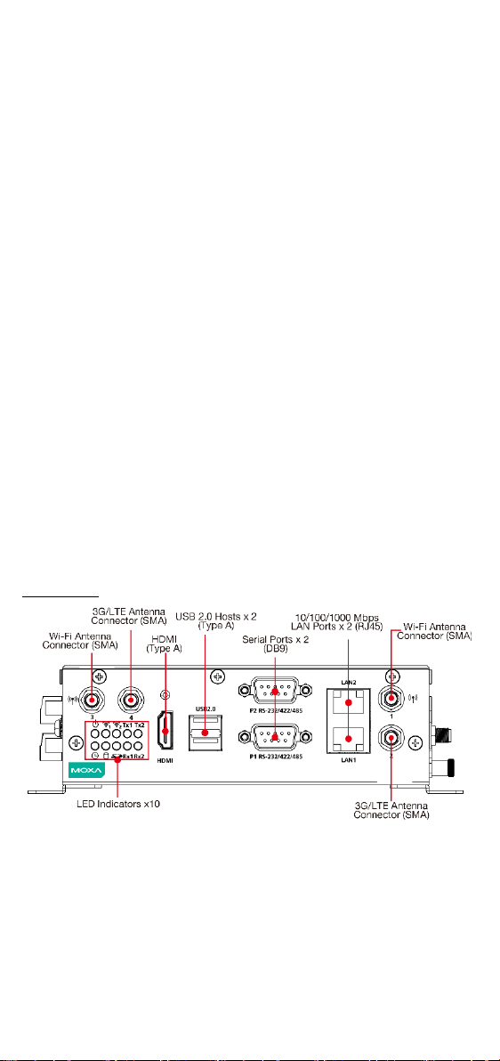
V2201 Panel Layout
The following figures show the panel layouts of the V2201-W models; for
“non-W” models, the 5 antenna connectors will not be installed during
production.
Front View
- 2 -
Page 3
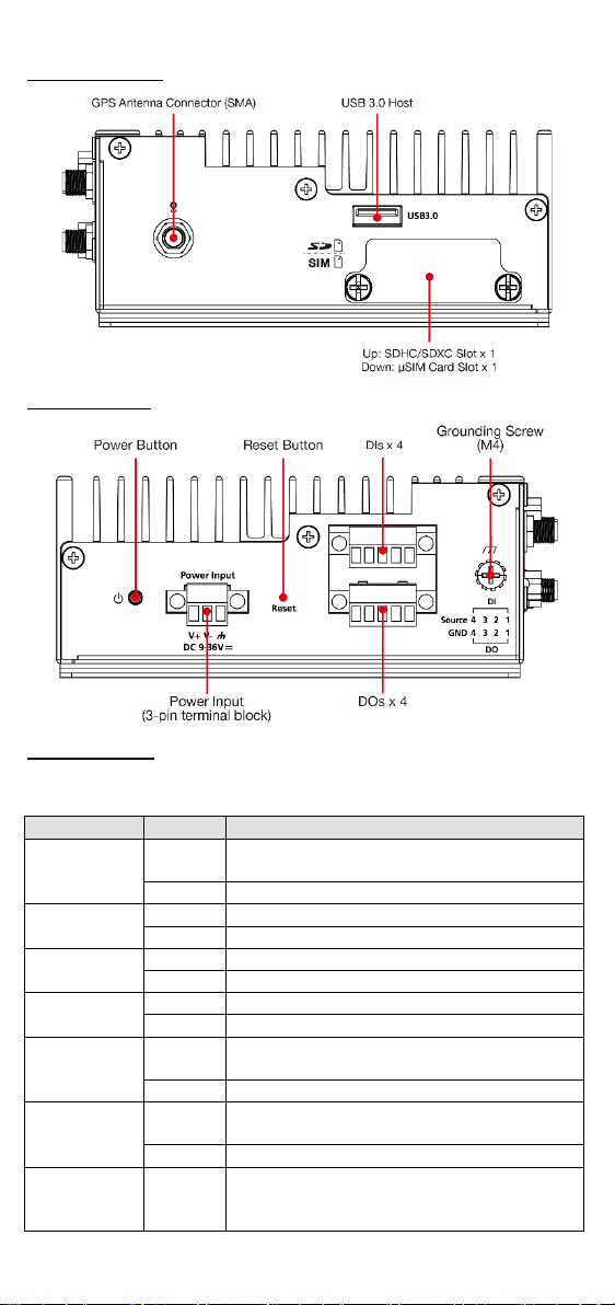
Right Side View
LED Name
Status
Function
Power
Green
Power is on and computer is functioning
normally.
Off
Power is off
Red
Event has occurred
Off
No alert
mSATA
Yellow
Blinking: Data is being transmitted
Off
Not connected / No data transmission
SD Card
Yellow
Blinking: Data is being transmitted
Off
Not connected / No data transmission
Wireles s 1
Green
Steady On: Link is On
Blinking: Data is being transmitted
Off
Not connected
Wireles s 2
Green
Steady On: Link is On
Blinking: Data is being transmitted
Off
Not connected
LAN 1
Yellow
Steady On: 1000 Mbps Ethernet link
Left-side View
LED Indicators
The following table describes the LED indicators located on the front panel
of the V2201.
User Defined
Blinking: Data is being transmitted
- 3 -
Page 4
LED Name
Status
Function
Green Steady On: 100 Mbps Ethernet link
Blinking: Data is being transmitted
Off
10 Mbps Ethernet link or LAN is not connected
LAN 2
Yellow
Steady On: 1000 Mbps Ethernet link
Blinking: Data is being transmitted
Green
Steady On: 100 Mbps Ethernet link
Blinking: Data is being transmitted
Off
10 Mbps Ethernet link or LAN is not connected
Green
Blinking: Data is being transmitted
Off
Not connected
Tx 2
Green
Blinking: Data is being transmitted
Off
Not connected
Rx 1
Yellow
Blinking: Data is being transmitted
Off
Not connected
Rx 2
Yellow
Blinking: Data is being transmitted
Off
Not connected
NOTE
The Mini PCIe card’s LED behavior depends on the module
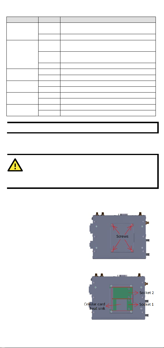
ATTENTION
“
cellular card heat
sink and 5 wireless SMA connectors
production process.
STEP1:
the middle
and
open the bottom cover.
Socket 1:
mini
MC9090, MC7304,
NOTE:
ellular card heat sink
is installed
Socket 2:
signals, for
(SparkLAN WPEA
Tx 1
Installing the Wireless Modules
-W” models (e.g., V2201-E2-W-T) will have a
The V2201 has two mini-PCIe sockets on the bottom panel. One socket
supports USB signals only, using the MC9090, MC7354, or MC7354
mini-PCIe cards. Another socket supports standard USB + PCIe signals.
Loosen the four screws in
of the bottom panel
installed during the
There are two mini-PCIe sockets:
USB signal, for 3G/LTE
-PCIe card (Sierra Wireless
The c
Standard USB + PCIe
or MC7354).
in socket 1.
Wi-Fi mini-PCIe card
-252NI).
- 4 -
Page 5

STEP 2: Insert the wireless module
card
at an angle.
STEP 3:
card
screws
product
STEP 4: Connect the connectors
with the corresponding wireless
module cards.
5 connectors
mini
No. 1 & No. 3:
No.
No. 5:
Installation:
STEP 1
Insert the upper lip of the DIN rail into the
DIN
STEP 2
Press the V2201 towards the DIN rail until
it snaps into place.
Push the wireless module
down and fasten it with the 2
that were included with the
.
are attached to the
-PCIe sockets:
Wi-Fi mini-PCIe card
2 & No. 4:
3G/LTE min i-PCIe card
GPS
STEP 5: Repla ce the bottom cover.
STEP 6: You may also purchase external 3G, 4G, and Wi-Fi antennas
from Moxa. Please contact a Moxa sales representative for information.
After installing the wireless modules and wireless external antennas, the
computer should appear as follows:
Installing the V2201
DIN-rail Mounting
The DK-DC50131 die-cast metal kit, which is shipped with the product,
enables easy and robust installation of the V2201. Use the six M4*6L FMS
screws inclu ded t o attach the DIN-rail mounting kit tightly to the side
panel of the V2201.
:
-rail mounting kit.
:
- 5 -
Page 6

Removal:
STEP 1
:
Pull down the latch on the
mounting kit with a scre wdriver.
STEP 2 & 3
Use a screwdriver to pry the
V2201
away from
the DIN
V2201
to remove it from
the DIN
STEP 4
Press the recessed button on the
spring
position
install the V2201 to a
Step 1:
Use two screws for each bracket
and attach the bracket to the
rear of the V2201.
Step 2:
Use two screws on each side to
attach the V2201 to a wall or
cabinet.
The product package does not
include the four screws required
for attaching the wa
mounting
kit to the wall; they need to be
purchased separately. We
recommend
M3*5L
standard screws.
:
slightly forward
rail, and then lift the
upwards
rail.
:
-loaded bracket to lock it into
until the next time you need to
Wall or Cabinet Mounting
The V2201 comes with two metal brackets for attaching it to a wall or the
inside of a ca binet. Four screws (Phillips truss-headed M3*6L nickel
plated with Nylok®) are included in the kit.
DIN rail.
ll-
that you use
- 6 -
Page 7

ATTENTION
This equipment is intended to be used in Restricted Access
Locations, such as a computer room, with
SERVICE PERSONAL or USERS who have been instructed on how
to handle the metal
special protection may be needed before touching it. The location
should only be accessible with a key or through a security identity
system.
ATTENTION
The power cord of
outlet with earthing connection.
ATTENTION
This product is intended to be supplied by a Listed Power Adapter
or DC power source, output rated 9 to 36 VDC, 3.5 to 1 A
minimum, Tma = 85 degree C minimum.
access limited to
chassis of equipment that is so hot that
Connector Description
Power Connector
Connect the 9 to 36 VDC LPS or Class 2 power line to the V2201’s terminal
block. If the power is supplied properly, the Power LED will light up. The
OS is ready when the Ready LED glows a solid green.
the adapter should be connected to a socket
Grounding the V2201
Grounding and wire routing help limit the effects of noise due to
electromagnetic interference (EMI). Run the ground connection from the
grounding screw (M4) to the grounding surface prior to connecting the
power.
- 7 -
Page 8

ATTENTION
This product is intended to be
mounting surface, such as a metal panel.
SG:
Protected Ground) contact is the right most of the
3
viewed from the angle shown here. Connect the
S
surface.
Pin
10/100 Mbps
1000 Mbps
1
ETx+
TRD(0)+
2
ETx-
TRD(0)-
3
ERx+
TRD(1)+ 4 –
TRD(2)+ 5 ---
TRD(2)-
6
ERx-
TRD(1)- 7 –
TRD(3)+ 8 –
TRD(3)-
mounted to a well-grounded
HDMI Outputs
The V2201 comes with a type A HDMI female connector on the front panel
to connect an HDMI monitor.
The screw hole above the HDMI connector is used to attach a custom lock
to the HDMI connector; a custom lock is needed since the shape of
different HDMI connectors are not the same. Please contact a Moxa sales
representative for details.
The lock appears as shown below:
The lock should appear as follows after it is attached to the V2201:
The Shielded Ground (sometimes called
-pin power terminal block connector when
G wire to an appropriate grounded metal
Ethernet Ports
The 10/100/1000 Mbps Ethernet ports use RJ45 connectors.
- 8 -
Page 9
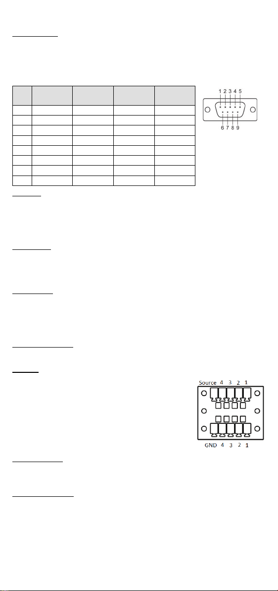
Serial Ports
RS-485
(4-wire)
RS-485
(2-wire)
1
DCD
TxDA(-)
TxDA(-)
– 2 RxD
TxDB(+)
TxDB(+)
– 3 TxD
RxDB(+)
RxDB(+)
DataB(+)
4
DTR
RxDA(-)
RxDA(-)
DataA(-)
5
GND
GND
GND
GND 6 DSR – – – 7
RTS – – – 8
CTS – –
–
The V2201 comes with 4 digital inputs and 4 digital
outputs
The serial ports use DB9 connectors. Each port can be configured by
software for RS-232, RS-422, or RS-485. The pin assignments for the
ports are shown in the following table:
Pin RS-232 RS-422
SD Slot
The V2201 has an SD slot for storage expansion. The SD slot allows users
to plug in an SD 3.0 standard SD card. To install an SD card, gently
remove the outer cover from the left, and then insert the SD card into the
slot.
USIM Slot
The V2201 has a USIM slot for 3G/LTE wireless Internet connections. To
install a USIM card, gently remove the outer cover from the left, and then
insert the USIM card into the slot.
USB Hosts
The V2201 has 1 USB 3.0 and 2 USB 2.0 Type-A connectors. 2 USB 2.0
ports are located on the front panel, and 1 USB 3.0 port is on the right
panel. The port supports keyboard and mouse, and can also be used to
connect a Flash drive for storing large amounts of data.
Audio Interface
The audio output of the V2201 is combined with the HDMI connector.
DI/DO
on a 2x5 terminal block.
Reset Button
Press the “Reset Button” on the left side panel of the V2201 to reboot the
system automatically.
Real-time Clock
The V2201’s real-time clock is powered by a lithium battery. We strongly
recommend that you do not replace the lithium battery without help from
a qualified Moxa support engineer. If you need to change the battery,
contact the Moxa RMA service team.
- 9 -
Page 10

ATTENTION
There is a risk of explosion if the battery is replaced by an
incorrect type of battery.
Default IP Address
Netmask
LAN 1
192.168.3.127
255.255.255.0
LAN 2
192.168.4.127
255.255.255.0
STEP 1:
Go to Start Control Panel Network and Internet View
network status and tasks
STEP 2:
In the Local Area Connection Properties screen, click Internet
Protocol (TCP/IP) and then select Properties. Select Internet
Protocol Version 4, and then click Properties.
STEP 3:
Click OK after inputting the proper IP address and netmask.
Powering on the V2201
To power on the V2201, connect the “terminal block to power jack
converter” to the V2201’s DC terminal block (located on the side panel),
and then connect the 9 to 36 VDC power adapter. The computer will be
automatically turned on once the power adapter is plugged in. If it does
not, press the Power Button to turn on the computer. Note that the
Shielded Ground wire should be connected to the top pin of the terminal
block. It takes about 30 seconds for the system to boot up. Once the
system is ready, the Power LED will light up.
Connecting the V2201 to a PC
Power on the V2201 computer after connecting a monitor, keyboard, and
mouse, and verifying that the power source is ready. Once the operating
system boots up, the first step is to configure the Ethernet interface. The
factory default settings for the V2201’s LANs are show below (W7E uses
DHCP).
Configuring the Ethernet Interface
Linux users should follow these steps:
If you use the console cable to configure network settings for the first
time, use the following commands to edit the interfaces file:
#ifdown –a
//Disable LAN1~LAN2 interface first, before you
reconfigure the LAN settings. LAN1 = eth0, LAN2 = eth1//
#vi /etc/network/interfaces
//check the LAN interface first//
After the boot setting of the LAN interface has been modified, use the
following commands to immediately activate the LAN settings:
#sync; ifup –a
W7E users should follow these steps:
Change adapter setting.
- 10 -
Page 11

NOTE
Refer to the V2201 user’s manuals for other
information.
configuration
- 11 -
 Loading...