

Moxa UC-8220-T-LX-EU-S, UC-8220-T-LX, UC-8220-T-LX-AP-S, UC-8210-T-LX, UC-8220-T-LX-US-S User Manual
...Page 1

UC-8200 Series Hardware User’s Manual
Edition 1.0, August 2019
www.moxa.com/product
© 2019 Moxa Inc. All rights reserved.
Page 2

UC-8200 Series Hardware User’s Manual
Moxa Americas
Toll
Tel:
Fax:
Moxa China (Shanghai office)
Toll
Tel:
Fax:
Moxa Europe
Tel:
Fax:
Moxa Asia
Tel:
Fax:
Moxa India
Tel:
Fax:
The software described in this manual is furnished under a license agreement and may be used only in accordance with
the terms of that agreement.
Copyright Notice
© 2019 Moxa Inc. All rights reserved.
Trademarks
The MOXA logo is a registered trademark of Moxa Inc.
All other trademarks or registered marks in this manual belong to their respective manufacturers.
Disclaimer
Information in this document is subject to change without notice and does not represent a commitment on the part of
Moxa.
Moxa provides this document as is, without warranty of any kind, either expressed or implied, including, but not limited
to, its particular purpose. Moxa reserves the right to make improvements and/or changes to this manual, or to the
products and/or the programs described in this manual, at any time.
Information provided in this manual is intended to be accurate and reliable. However, Moxa assumes no responsibility for
its use, or for any infringements on the rights of third parties that may result from its use.
This product might include unintentional technical or typographical errors. Changes are periodically made to the
information herein to correct such errors, and these changes are incorporated into new editions of the publication.
Technical Support Contact Information
www.moxa.com/support
-free: 1-888-669-2872
+1-714-528-6777
+1-714-528-6778
+49-89-3 70 03 99-0
+49-89-3 70 03 99-99
+91-80-4172-9088
+91-80-4132-1045
-free: 800-820-5036
+86-21-5258-9955
+86-21-5258-5505
+886-2-8919-1230
-Pacific
+886-2-8919-1231
Page 3

Table of Contents
1. Introduction ...................................................................................................................................... 1-1
Model Descriptions .............................................................................................................................. 1-2
Package Checklist ............................................................................................................................... 1-2
Product Features ................................................................................................................................ 1-2
Product Specifications ......................................................................................................................... 1-2
2. Hardware Introduction...................................................................................................................... 2-1
Appearance ........................................................................................................................................ 2-2
UC-8210 Series ........................................................................................................................... 2-2
UC-8220 Series ........................................................................................................................... 2-3
Dimensions ........................................................................................................................................ 2-5
LED Indicators .................................................................................................................................... 2-6
Reboot .............................................................................................................................................. 2-6
Reset to Default ................................................................................................................................. 2-7
Real-time Clock .................................................................................................................................. 2-7
Installation Options ............................................................................................................................. 2-7
DIN-rail Mounting ........................................................................................................................ 2-7
Wall Mounting (optional) .............................................................................................................. 2-8
3. Hardware Connection Description ..................................................................................................... 3-1
Wiring Requirements ........................................................................................................................... 3-2
Connecting the Power .................................................................................................................. 3-2
Grounding the Unit ...................................................................................................................... 3-3
Connecting to the Network ................................................................................................................... 3-3
Connecting to a USB Device ................................................................................................................. 3-3
Connecting to Serial Ports .................................................................................................................... 3-3
Inserting the microSD Card .................................................................................................................. 3-4
Connecting to the Console Port ............................................................................................................. 3-4
Connecting the CAN Port ..................................................................................................................... 3-4
Connecting the Digital Inputs and Digital Outputs ................................................................................... 3-5
Inserting the SIM Card ........................................................................................................................ 3-5
Installing the Cellular Module ............................................................................................................... 3-5
Installing the Wi-Fi Module ................................................................................................................... 3-7
Connecting the Antennas ..................................................................................................................... 3-9
A. Regulatory Approval Statements ....................................................................................................... A-1
Page 4

1
1. Introduction
The UC-8200 computing platform is designed for embedded data-acquisition applications. The UC-8200
platform comes with two RS-232/422/485 serial ports and dual 10/100/1000 Mbps Ethernet LAN ports, as well
as a Mini PCIe socket to support cellular and Wi-Fi modules. These versatile communication capabilities let
users efficiently adapt the UC-8200 to a variety of complex communications solutions.
The following topics are covered in this chapter:
Model Descriptions
Package Checklist
Product Features
Product Specifications
Page 5

UC-8200 Series Hardware Introduction
1-2
NOTE
Notify your sales representative if any of the above items are missing or damaged.
NOTE
The latest specifications for Moxa's products can be found at
Model Descriptions
The UC-8200 Series includes the following models:
• UC-8210-T-LX: Industrial computing platform with 2 serial ports, 2 Ethernet ports, 1 CAN port, USB, micro
SD socket, -40 to 85°C operating temperature range
• UC-8210-T-LX-S:Industrial computing platform with 2 serial ports, 2 Ethernet ports, 1 CAN port, TPM,
USB, micro SD socket, -40 to 85°C operating temperature range
• UC-8220-T-LX: Industrial computing platform with 2 serial ports, 2 Ethernet ports, 1 CAN port, USB, micro
SD socket, LTE, Wi-Fi, -40 to 85°C operating temperature range
• UC-8220-T-LX-US-S: Industrial computing platform with 2 serial ports, 2 Ethernet ports, 1 CAN port, TPM,
USB, micro SD socket, USA LTE band, Wi-Fi, -40 to 85°C operating temperature range
• UC-8220-T-LX-EU-S: Industrial computing platform with 2 serial ports, 2 Ethernet ports, 1 CAN port, TPM,
USB, micro SD socket, Europe LTE band, Wi-Fi, -40 to 85°C operating temperature range
• UC-8220-T-LX-AP-S: Industrial computing platform with 2 serial ports, 2 Ethernet ports, 1 CAN port, TPM,
USB, micro SD socket, Asia/Pacific LTE band, Wi-Fi, -40 to 85°C operating temperature range
Package Checklist
Before installing a UC-8200 computer, verify that the package contains the following items:
• UC-8200 Series embedded computer
• Power jack
• Console cable
• DIN-rail mounting kit
• Quick installation guide (printed)
• Warranty card
Product Features
• Armv7 Cortex-A7 dual core 1 GHz
• 2 auto-sensing 10/100 Mbps Ethernet ports
• SD socket for storage expansion
• Programmable LEDs and a programmable button for easy installation and maintenance
• Mini PCIe socket for cellular module
• Debian 9 open platform
• -40 to 70°C wide temperature range with LTE enabled
Product Specifications
https://www.moxa.com.
Page 6

2
2. Hardware Introduction
The UC-8200 embedded computers are compact and rugged, making them suitable for industrial applications.
The LED indicators allow you to monitor device performance and quickly identify issues, and the multiple ports
can be used to connect a variety of devices. The UC-8200 Series comes with a reliable and stable hardware
platform that lets you devote the bulk of your time to application development. In this chapter, we provide
basic information about the embedded computer’s hardware and its various components.
The following topics are covered in this chapter:
Appearance
UC-8210 Series
UC-8220 Series
Dimensions
LED Indicators
Reset to Default
Real-time Clock
Installation Options
DIN-rail Mounting
Wall Mounting (optional)
Page 7
UC-8200 Series Hardware Hardware Introduction
2-2
Appearance
UC-8210 Series
Top Panel View
Front Panel View
Page 8

UC-8200 Series Hardware Hardware Introduction
2-3
Bottom Panel View
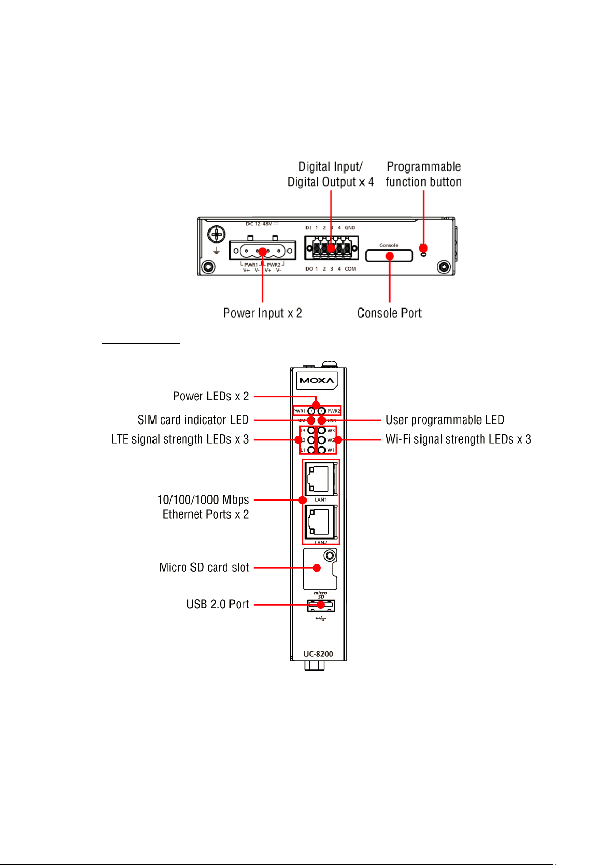
UC-8220 Series
Top Panel View
Page 9

UC-8200 Series Hardware Hardware Introduction
2-4
Front Panel View
Bottom Panel View
Page 10

UC-8200 Series Hardware Hardware Introduction
2-5
Dimensions
Unit: mm (in)
UC-8210 Series
Page 11

UC-8200 Series Hardware Hardware Introduction
2-6
UC-8220 Series
LED Indicators
The function of each LED is described in the table below:
LED Name Status Function
PWR1/PWR2 Green Power is on
SIM Green SIM2 in use
USR Green/Yellow User programmable
L1/L2/L3 Yellow Cellular signal strength
W1/W2/W3 Yellow WLAN signal strength
LAN1/LAN 2
(RJ45 connector)
Off No power
Yellow SIM1 in use
L1+L2+L3: Strong
L2+L3: Normal
L3:Weak
L1+L2+L3: Strong
L2+L3: Normal
L3: Weak
Green Steady on 1000 Mbps Ethernet link
Blinking Data is being transmitted
Yellow Steady on 100 Mbps Ethernet link
Blinking Data is being transmitted
Off No Ethernet connection
Reboot
To reboot the computer, press the programmable button for 1 second.
Page 12

UC-8200 Series Hardware Hardware Introduction
2-7
WARNING
There is a risk of explosion if the battery is replaced
UC-8210
UC-8220
Insert the top of the DIN rail into
Reset to Default
Press and hold the Programmable function (FN) button between 7 to 9 seconds to reset the computer to the
factory default settings. When the reset button is held down, the User programmable (USR) LED will blink
once every second and become steady after 7 to 9 seconds. Release the button within this period to load the
factory default settings.
Real-time Clock
The UC-8200’s real time clock is powered by a non-chargeable battery. We strongly recommend that you do
not replace the lithium battery without help from a qualified Moxa support engineer. If you need to change the
battery, contact the Moxa RMA service team.
Installation Options
DIN-rail Mounting
The aluminum DIN-rail attachment plate is already attached to the product’s casing. To mount the UC-8200 on
to a DIN rail, make sure that the stiff metal spring is facing upwards and follow these steps.
1. Pull down the bottom slider of the
DIN-rail bracket located at the
back of the unit
2.
the slot just below the upper
hook of the DIN-rail bracket.
3. Latch the unit firmly on to the
DIN rail as shown in the
illustrations below.
4. Push the slider back into place.
with an incorrect type.
Page 13

UC-8200 Series Hardware Hardware Introduction
2-8
IMPORTANT!
The diameter of the screw heads should be greater than 7 mm and less than 14 mm; the diameter of the shafts
should be less than 3 mm. The length of the screws should be greater than 6 mm.
NOTE
one of the keyhole shaped apertures of the
•
Wall Mounting (optional)
The UC-8200 Series can be mounted on to a wall using a wall-mounting kit as shown in the following
illustrations. The optional wall-mounting kit is not included in the product package and should be purchased
separately.
Follow these steps to mount the computer on to a wall:
Step 1
Use four screws to fasten the wall-mounting
brackets on the left panel of the computer.
Step 2
Use another four screws to mount the computer on
a wall or a cabinet.
• Test the screw head and shank size by inserting the screws into
wall-mounting plates before attaching the plate to the wall.
• Do not drive the screws in all the way—leave a space of about 2 mm to allow room for sliding the wall
mount panel between the wall and the screws.
Page 14

3
3. Hardware Connection Description
In this chapter, we describe how to connect the UC-8200 to a network and various devices.
The following topics are covered in this chapter:
Wiring Requirements
Connecting the Power
Grounding the Unit
Connecting to the Network
Connecting to a USB Device
Connecting to Serial Ports
Inserting the microSD Card
Connecting to the Console Port
Connecting the CAN Port
Connecting the Digital Inputs and Digital Outputs
Inserting the SIM Card
Installing the Cellular Module
Installing the Wi-Fi Module
Connecting the Antennas
Page 15

UC-8200 Series Hardware Hardware Connection Description
3-2
NOTE
Do not run signal or communication wiring and power wiring in the same wire conduit. To avoid interference,
wires with different signal characteristics should be routed separately.
ATTENTION
Safety Fir
Be sure to disconnect the power cord before doing installations and/or wiring.
Electrical Current
Calculate the maximum possible current in each power wire and common wire. Observe all electrical codes
dictating the maximum current allowable
If the current goes above the maximum ratings, the wiring could overheat, causing serious damage to your
equipment.
Temperature Caution!
Be
at, and
consequently the
Connect the power jack (in the package) to the UC-8200 Series’ DC terminal block
(located on the top panel), and then connect the power adapter. It takes about 30
seconds for the system to boot up. Once the system is ready, the Power LED will
light up. Both models support dual power inputs for redundancy.
WARNING
• This product is intended to be supplied by a UL Listed Power Adapter or DC power source marked ‘L.P.S.”
•
If you need further information or assistance, contact a Moxa representative.
Wiring Requirements
In this section, we describe how to connect various devices to the embedded computer. Be sure to read and
follow these common safety precautions before proceeding with the installation of any electronic device:
• Use separate paths to route wiring for power and devices. If power wiring and device wiring paths must
cross, make sure the wires are perpendicular at the intersection point.
• You can use the type of signal transmitted through a wire to determine which wires should be kept separate.
The rule of thumb is that wiring that shares similar electrical characteristics can be bundled together.
• Keep input wiring and output wiring separate.
• When necessary, it is strongly advised that you label wiring to all devices in the system.
careful when handling the unit. When the unit is plugged in, the internal components generate he
st!
Caution!
outer casing may feel hot to the touch.
Connecting the Power
for each wire size.
(or “Limited Power Source”) rated 12-48 VDC, 0.25 A (minimum), and Tma= 85°C (minimum).
The power adapter should be connected to a socket outlet with earthing connection.
Page 16

UC-8200 Series Hardware Hardware Connection Description
3-3
ATTENTION
A shielded power cor
nearby
radio and television reception. It is essential that only the supplied power cord be used.
You are cautioned that changes or modifications not expressly approved by the party responsible for
compliance could void your authority to operate
1 – TxD-(A)
– 2 RxD
TxD+(B)
– 3 TxD
RxD+(B)
Data+(B)
4
DTR
RxD-(A)
Data-(A)
5
GND
GND
GND
6
DSR – – 7 RTS – –
8
CTS – –
Grounding the Unit
There is a grounding connector on the top panel of the computer. Use this connector to connect a
well-grounded mounting surface, such as a metal panel. Grounding and wire routing help limit the effects of
noise due to electromagnetic interference (EMI).
d is required to meet FCC emission limits and also to prevent interference with
the equipment.
Connecting to the Network
The two Ethernet ports are located on the front panel of the UC-8200 computers. The pin assignments for the
Ethernet port are shown in the following figure. If you are using your own cable, make sure that the pin
assignments on the Ethernet cable connector match the pin assignments on the Ethernet port.
Pin 10/100 Mbps 10/100/1000 Mbps
1 Tx+ TRD(0)+
2 Tx- TRD(0)-
3 Rx+ TRD(1)+
4 – TRD(2)+
5 – TRD(2)-
6 Rx- TRD(1)-
7 – TRD(3)+
8 – TRD(3)-
Connecting to a USB Device
The UC-8200 Series computers come with a USB port located at the lower part of the front panel, allowing users
to connect to a device with an USB interface. The USB port uses a type A connector. By default, the USB storage
is mounted at /mnt/usbstorage.
Connecting to Serial Ports
The two serial ports (P1 and P2) use terminal connectors. Each port can be configured by software for RS-232,
RS-422, or RS-485. The pin assignments for the ports are shown in the following table:
Pin RS-232
RS-422/
RS-485
RS-485
2w
Page 17

UC-8200 Series Hardware Hardware Connection Description
3-4
Pin
Signal
1 – 2
CAN_L
3
CAN_GND
4 – 5
(CAN_SHLD)
6
(GND)
7
CAN_H 8 –
9
(CAN_V+)
Inserting the microSD Card
The UC-8200 Series comes with a microSD socket for storage expansion. The microSD socket is located at the
lower part on the front panel. To install the card, remove the screw and the protection cover to access the
socket, and then insert the microSD card into the socket directly. You will hear a click when the card is in place.
To remove the card, push the card in before releasing it.
Connecting to the Console Port
The con sole port is an RS-232 port located on the top panel, and can be connected to a 4-pin pin header cable. You can use
this port for debugging or firmware upgrade.
1 TxD
2 RxD
3 NC
4 GND
Connecting the CAN Port
There is a CAN port in DB9 interface, located on the bottom panel. Refer to the figure on the left for detailed pin
definitions.
Pin Definition
Page 18

UC-8200 Series Hardware Hardware Connection Description
3-5
Connecting the Digital Inputs and Digital Outputs
There are four digital inputs and four digital outputs on the top panel. Refer to the
figure on the left for detailed pin definitions.
Inserting the SIM Card
The UC-8220 computer comes with a SIM card socket that allows users to install two SIM card for the cellular
communication.
Step 1
Remove the screw on the SIM card holder cover
located on the bottom panel of the UC-8220
computer.
Step 2
Insert the SIM card into the socket. Make sure you
insert in the right direction. To remove the SIM card,
press the SIM card in to release and then you can pull
out the SIM card.
Installing the Cellular Module
The UC-8220 Series comes with two PCIe sockets, allowing users to install a cellular and a Wi-Fi module. Some
models have been shipped with a built-in cellular module inside the computer. However, if you purchase the
UC-8200 Series without a cellular module, follow these steps to install the cellular module.
1. Remove the four screws on a side panel of the
computer.
2. Remove the two screws on the other side panel
to open the side cover of the computer.
Page 19

UC-8200 Series Hardware Hardware Connection Description
3-6
3. The socket is located on the main board of the
computer.
5. Connect the antenna cables to the antenna connectors.
4. Install the cellular module onto the socket, and
fasten the two screws on the module.
6. The UC-8220 Series supports two cellular antennas and a GPS antenna. Connect the cables to the correct
antenna connectors.
7. When finished, replace the side cover and put the screws back to secure the cover.
Page 20

UC-8200 Series Hardware Hardware Connection Description
3-7
Installing the Wi-Fi Module
The Wi-Fi module is not included in the package, you need to purchase separately. The Wi-Fi module package includes the
following items.
Follow these steps to install the Wi-Fi module for the UC-8220 Series.
1. Remove the side cover of the computer to expose the Wi-Fi module socket.
The Wi-Fi socket is located beside the cellular module socket.
Page 21

UC-8200 Series Hardware Hardware Connection Description
3-8
Remove the two silver screws on the socket.
4. Remove the plastic protection covers on the antenna connectors.
Install the Wi-Fi module in the socket and fasten two
black screws on the module. Also, fasten the two
bronze screws on the board.
5. Connect the antenna cables to the antenna connectors.
The Wi-Fi module supports two antenna connectors; connect the cables to the correct antenna connectors.
Page 22

UC-8200 Series Hardware Hardware Connection Description
3-9
6. . Install the heat sink pad on the module and then fasten two silver screws.
7. Replace the side cover.
Connecting the Antennas
There are two cellular antenna connectors (C1 and C2) on the
front panel of the UC-8220 Series. In addition, a GPS connector is
provided for the GPS module. All three connectors are of SMA
type. Connect the antennas to these connectors as shown below.
There are two Wi-Fi antenna connectors (W1 and W2) on the top panel of
the UC-8220 Series. Connect the antennas on the connectors as shown
below. Both W1 and W2 connectors are of RP-SMA type.
Page 23

This device complies with part 15 of the FCC Rules. Operation is subject to the following
two conditions: (1) This device may not cause harmful interference, and (2) this dev
must accept any interference received, including interference that may cause undesired
operation.
European Community
WARNING
This is a class A product. In a domestic environment this product may cause radio interference in which case
the user may be required to take adequate measures.
A
A. Regulatory Approval Statements
ice
Class A: FCC Warning! This equipment has been tested and found to comply with the limits for a Class A digital
device, pursuant to part 15 of the FCC Rules. These limits are designed to provide reasonable protection
against harmful interference when the equipment is operated in a commercial environment. This equipment
generates, uses, and can radiate radio frequency energy and, if not installed and used in accordance with the
instruction manual, may cause harmful interference to radio communications. Operation of this equipment in
a residential area is likely to cause harmful interference in which case the users will be required to correct the
interference at their own expense.
 Loading...