

Page 1

P/N: 1802082000012
Technical Support Contact Information
www.moxa.com/support
2021 Moxa Inc. All rights reserved.
UC-8200 Series
Quick Installation Guide
Version 2.1, January 2021
*1802082000012*
Page 2
Overview
IMPORTANT!
Notify your sales representative if any of the above items are
missing or damaged.
The UC-8200 Series computing platform is designed for embedded data
acquisition applications. The UC-8200 Series computer comes with two
RS-232/422/485 serial ports and dual 10/100/1000 Mbps Ethernet LAN
ports, as well as two Mini PCIe sockets to support cellular and Wi-Fi
modules. These versatile communication capabilities let users efficiently
adapt the UC-8200 Series to a variety of complex communications
solutions.
Package Checklist
Before installing the UC-8200 Series, verify that the package contains
the following items:
• UC-8200 Series embedded computer
• Power jack
• Console cable
• DIN-rail mounting kit
• Quick insta llation guide (printed)
• Warranty card
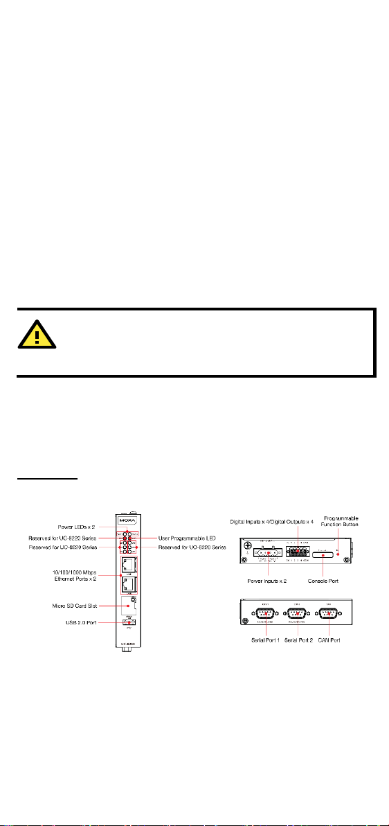
Panel Layout
The following figures show the panel layouts of the UC-8200 Series:
UC-8210
Panel View
- 2 -
Page 3
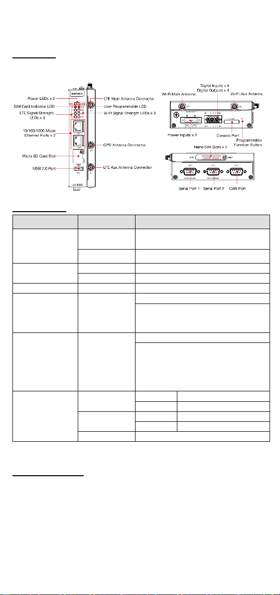
UC-8220
LED Name
Status
Function
PWR1/PWR2
Green
Power is on
SIM
Green
SIM2 in use
Yellow
SIM1 in use
USR
Green/Yellow
User programmable
Cellular signal strength
L1+L2+L3: Strong
L3:Weak
W1/W2/W3
Yellow
WLAN signal strength
L1+L2+L3: strong
Steady on
1000 Mbps Ethernet link
Blinkin g
Data is being transmitted
Yellow
Steady on
100 Mbps Ethernet link
Blinkin g
Data is being transmitted
Off
No Ethernet connection
Panel View
LED Indicator
Off No power
L1/L2/L3 Yellow
L2+L3: Normal
L2+L3: normal
L3: weak
LAN1/LAN 2
(RJ45 connector)
Green
Installing the UC-8200 Series
DIN-rail Mounting
The aluminum DIN-rail attachment plate is already attached to the
product’s casing. To mount the UC-8200 Series on to a DIN rail, make
sure that the stiff metal spring is facing upwards and follow these
steps.
- 3 -
Page 4
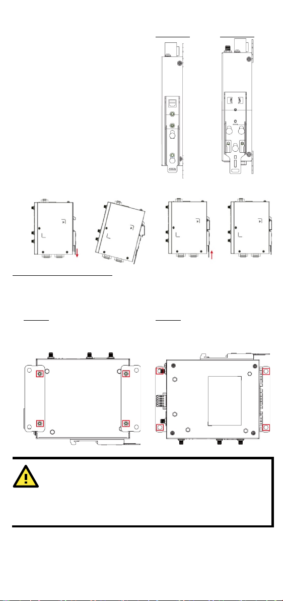
1. Pull down the bottom slider
of the DIN-rail bracket
UC-8210
UC-8220
left panel of the computer.
wall or in a cabinet.
IMPORTANT!
The diameter of the screw heads should be greater than 7 mm
and less than 14 mm; the diameter of the shafts should be less
than 3 mm. The length of
mm.
located at the back of the
unit
2. Insert the top of the DIN
rail int o the slot just below
the upper hook of the DINrail bracket.
3. Latch the unit firmly on to
the DIN rail as shown in the
illustrations below.
4. Push the slider back into
place.
Wall Mounting (optional)
The UC-8200 Series can be mounted on to a wall using a wall-mounting
kit. The optional wall-mounting kit should be purchased separately.
Follow these steps to mount the computer on to a wall:
Step 1
Use four screws to fasten the
wall-mounting brackets on the
Step 2
Use another four screws to
mount the computer on to a
the screws should be greater than 6
- 4 -
Page 5

NOTE
• Test the screw head and shank size by inserting the screws
into one of the keyhole shaped apertures of the wall-
•
between the wall and the screws.
WARNING
•
SELV/LPS. The power source must be rated 12 to 48 VDC,
•
If you need fu
representative.
Pin
10/100 Mbps
1000 Mbps
1
Tx+
TRD(0)+
2
Tx-
TRD(0)-
3
Rx+
TRD(1)+
4 – TRD(2)+
5 – TRD(2)-
6
Rx-
TRD(1)- 7 –
TRD(3)+
8 – TRD(3)-
mounting plates before attaching the plate to the wall.
Do not drive the screws in all the way—leave a space of
about 2 mm to allow room for sliding the wall mount panel
Connector Description
Power Connector
Connect the power jack (in the package)
to the UC-8200 Series’ DC terminal
block (located on the top panel), and
then connect the power adapter. It takes
about 30 seconds for the system to boot
up. Once the system is ready, the Power
LED will light up. Both models support
dual power inputs for redundancy.
Use wires with 16 to 24 AWG (1.318 to 0.205 mm
2
) to connect to V+,
V-, and GND. The wire size of the power input and the earthing
conductor should be the same.
This product is intended to be supplied by a UL Listed
power adapter or DC power source whose output meets
minimum 1 A, and minimum Tma = 85°C.
The power adapter should be connected to a socket outlet
with earthing connection.
rther information or assistance, contact a Moxa
Grounding the Computer
There is a grounding connector located on the top panel of the
computer. Grounding and wire routing help limit the effects of noise
due to electromagnetic interference (EMI). Connect to an appropriate
grounded metal surface.
Ethernet Ports
The two 10/100/1000 Mbps Ethernet ports (LAN 1 and LAN 2) use RJ45
connectors.
- 5 -
Page 6

Serial Ports
4w
1 – TxD-(A)
– 2 RxD
TxD+(B)
– 3 TxD
RxD+(B)
Data+(B)
4
DTR
RxD-(A)
Data-(A)
5
GND
GND
GND
6
DSR – – 7 RTS – –
8
CTS – –
Pin
Signal
1
TxD 2 RxD 3 NC 4 GND
The two serial ports (P1 and P2) use DB9 interface. Each port can be
configured by software for RS-232, RS-422, or RS-485. The pin
assignments for the ports are shown in the following table:
Pin RS-232
RS-422/
RS-485
RS-485
2w
microSD Card Sockets
The UC-8200 Series comes with a micro SD socket for storage
expansion. The microSD socket is located at the lower part on the front
panel. To install the card, remove the screw and the protection cover to
access the socket, and then insert the microSD card into the socket
directly. You will hear a click when the card is in place. To remove the
card, push the card in before releasing it.
Console Port
The console port is an RS-232 port located on the top panel, and can be
connected to a 4-pin pin header cable. You can use this port for
debugging or firmware upgrade.
USB Port
The USB 2.0 port is located at the lower part of the front panel and
supports a USB storage device driver. By default, the USB storage is
mounted at
/mnt/usbstorage.
- 6 -
Page 7

CAN Port
1 – 2
CAN_L
3
CAN_GND
4 – 5
(CAN_SHLD)
6
(GND)
7
CAN_H 8 –
9
(CAN_V+)
Step 1
Step 2
ATTENTION
There is
incorrect type of battery.
A CAN port with a DB9 interface is located on the bottom panel. Refer
to the figure below for detailed pin definitions.
Pin Definition
Digital Inputs/Outputs
There are four digital inputs and four
digital outputs on the top panel.
Refer to the figure on the left for
detailed pin defin itions.
SIM Card Socket
The UC-8220 computer comes with a SIM card socket that allows users
to install two SIM card for the cellular communication.
Remove the screw on the SIM
card holder cover located on the
bottom panel of the UC-8220
computer.
Insert the SIM card into the
socket. Make sure you insert in
the right direction. To remove
the SIM card, press the SIM
card in to release and then you
can pull out the SIM card.
Real-time Clock
The real-time clock in the UC-8200 Series is powered by a lithium
battery. We strongly recommend that you do not rep lace the lithium
battery without the help of a Moxa support engineer. If you need to
change the battery, contact the Moxa RMA service team.
a risk of explosion if the battery is replaced with an
- 7 -
Page 8

Accessing the UC-8200 Series Using a PC
ATTENTION
Remember to choose the
console cable to connect a PC to the
port.
Default IP Address
Netmask
LAN 1
192.168.3.127
255.255.255.0
LAN 2
192.168.4.127
255.255.255.0
ATTENTION
•
•
•
es that are to be installed
•
•
HAZARDOUS LOCATIONS MUST BE INSTALLED WITHIN THE
•
hazardous location.
You can use a PC to access the UC-8200 Series by one of the following
methods:
A. Through the ser ial console port with the following settings:
Baudrate=115200 bps, Parity=None, Data bits=8, Stop bits
=1, Flow Control=None
“VT100” terminal type. Use the
B. Using SSH over the network.
Refer to the following IP addresses and login information:
Login: moxa
Password: moxa
UC-8200's serial console
The equipment shall only be used in an area of not more
than pollution degree 2, as defined in EN 60664-1.
The equipment shall be installed in an enclosure that
provides a degree of protection not less than IP 54 in
accordance with EN 60079-15 and accessible only by the
use of a tool.
These devices are open-type devic
in an enclosure with tool removable cover or door, suitable
for the environment.
This equipment is suitable for use in Class I, Divis ion 2,
Groups A, B, C, and D or non-hazardous locations only.
ANTENNAS INTENDED FOR USE IN CLASS I, DIVISION 2
END-USE ENCLOSURE. FOR REMOTE MOUNTING IN AN
UNCLASSIFIED LOCATION, ROUTING AND INSTALLATION
OF THE ANTENNAS SHALL BE IN ACCORDANCE WITH
NATIONAL ELECTRICAL CODE REQUIREMENTS (NEC/CEC)
Sec. 501.10 (b).
The “USB, RS-232/422/485 serial ports, LAN1, LAN2, and
Console ports” and Reset Button may only be accessed for
equipment set-up, installation, and maintenance at a nonhazardous location. These ports and their associated
interconnect ing cables must remain inaccessible within the
- 8 -
Page 9

Installing the Cellular Module
1. Remove the four screws
2. Remove two screws on the
The UC-8220 Series comes with two PCIe sockets, allowing users to
install a cellular and a Wi-Fi module. Some models have been shipped
with a built-in cellular module inside the computer. However, if you
purchase the UC-8200 series without a cellular modu le, follow these
steps to install the cellular module.
on the side panel of the
computer.
3. The socket is located on the main board of the computer.
4. Install the cellular module onto the socket and fasten the two
screws on the module.
other side panel to open the
side cover of the computer.
- 9 -
Page 10

5. Connect the antenna cables to the antenna connectors.
6. The UC-8220 Series supports two cellular antennas and a GPS
antenna. Connect the cable to the correct antenna connectors.
7. When finished, place the side cover back on the computer and
secure it.
Installing the Wi-Fi Module
The Wi-Fi module is not included in the package, you need to purchase
separately. The Wi-Fi module package includes the follo wing items:
- 10 -
Page 11

Follow these steps to install the Wi-Fi module.
the board.
1. Remove the side cover of the computer to expose the Wi-Fi
module socket.
The Wi-Fi socket is located beside the cellular module socket.
2. Remove the two silver
screws on the socket.
3. Install the Wi-Fi module
in the socket and fasten
two black screws on the
module. Also, fasten the
two bronze screws on
- 11 -
Page 12

4. Remove the plastic protection covers on the antenna connectors.
5. Connect the antenna cables to the antenna connectors.
The Wi-Fi module supports two antenna connectors, connect the
cables to the correct antenna connectors.
6. Install the heat sink pad on the module and then fasten two silver
screws.
7. Replace the side cover.
- 12 -
Page 13

Connecting Antennas
Model
UC-8210-T-LX, UC-8210-T-LX-S, UC-8220-T-LX
Rating
Input: 12 to 48 VDC; 1.0 to 0.25 A
Rated Cable Temp ≧ 100°C
C1D2 Information
Temperature Code (T-code): T4
Manufacturer’s
Address
No. 1111, Heping Rd., Bade Dist., Taoyuan City
334004, Taiwan
Certification
EN 60079-15:2010
There are two cellular antenna
connectors (C1 and C2) on the
front panel of the UC-8220
Series. In addition, a GPS
connector is provided for the
GPS module. All three
connectors are of SMA type.
Connect the antennas to these
connectors as shown below.
There are two Wi-Fi antenna
connectors (W1 and W2) on the
top panel of the UC-8220 Series.
Connect the antennas on the
connectors as shown below. Both
W1 and W2 connectors are of RPSMA type.
ATEX and C1D2 Specifications
ATEX Information
II 3 G
Certificate Number: DEMKO 19 ATEX 2302X
Certification String: Ex nA IIC T4 Gc
Ambient Range: -40°C ≦ Tamb ≦ 70°C (with
LTE module for model UC-8220-T-LX)
Hazardous Location
EN 60079-0:2012+A11:2013
- 13 -
 Loading...