

Page 1

P/N: 1802081120021
Technical Support Contact Information
www.moxa.com/support
Moxa Americas:
Toll
Tel:
Fax:
Moxa China (Shanghai office):
Toll
Tel:
Fax:
Moxa Europe:
Tel:
Fax:
Moxa Asia-Pacific:
Tel:
Fax:
Moxa India:
Tel:
Fax:
2020 Moxa Inc. All rights reserved.
UC-8112-ME-T
Quick Installation Guide
Edition 2.1, July 2020
-free: 1-888-669-2872
1-714-528-6777
1-714-528-6778
+49-89-3 70 03 99-0
+49-89-3 70 03 99-99
+91-80-4172-9088
+91-80-4132-1045
-free: 800-820-5036
+86-21-5258-9955
+86-21-5258-5505
+886-2-8919-1230
+886-2-8919-1231
*1802081120021*
Page 2
Overview
The UC-8112-ME-T computing platform is designed for embedded data
acquisition application s. The UC-8112-ME-T computer comes with one or
two RS-232/422/485 serial ports and dual 10/100 Mbps Ethernet LAN
ports, as well as a Mini PCIe socket to support cellular modules. These
versatile communication capabilities let users efficiently adapt the
UC-8112-ME-T to a variety of complex communications so lutions.
Package Checklist
Before installing the UC-8112-ME-T, verify that the package contains the
following items:
• UC-8112-ME-T embedded computer
• Power jack
• 3-pin terminal block for power
• 5-pin terminal block for UART x 2
• Quick installation guide (printed)
• Warranty card
IMPORTANT: Notify your sales representative if any of the above items
are missing or damaged.
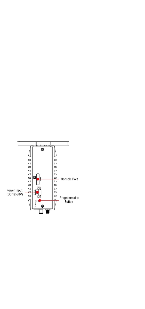
UC-8112-ME-T Panel Layout
The following figures show the panel layouts of the UC-8112-ME-T:
Top Panel View
- 2 -
Page 3
Bottom Panel View
LED Name
Color
Function
working normally.
Off
USB device is not connected.
normally.
Off
SD card is not detected.
Power is on and the computer is working
nor m a l l y.
Off
Power is off.
Steady On
100 Mbps Ethernet link
Blinkin g
Data transmission in progress
Steady On
10 Mbps Ethernet link
Blinkin g
Data transmission in progress
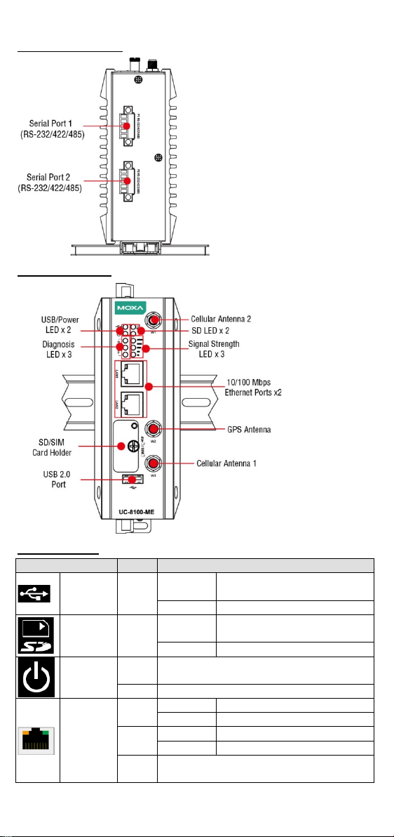
Front Panel View
LED Indicators
USB Green
SD Green
Power
LAN1/
LAN 2
(RJ45
connector)
Steady On
Steady On
Green
Green
Yel lo w
Ethernet is not connected.
Off
USB device is connected and
SD Card inserted and working
- 3 -
Page 4
LED Name
Color
Function
1 (Red): Poor
Off
Wireles s module is not detected.
These three LEDs are programmable. For
Default Programmable
Wireles s
Signal
Strength
The number of glowing LEDs indicates the
Green
signal strength.
3 (Green + Yellow + Red): Excellent
Yel lo w
2 (Yellow + Red): Good
Red
Programm
able
diagnostic
LEDs
Green
details, refer to the “
Yel lo w
Button Operation" section in the Hardware
User’s Manual.
Red
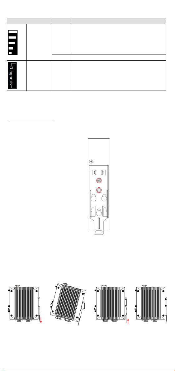
Installing the UC-8112-ME-T
Two sliders are provided at the back of the unit for DIN-rail mounting or
wall mounting.
DIN-Rail Mounting
1. The DIN-rail mounting kit is mounted by default as shown in the
figure below:
2. Pull down the bottom slider of the DIN-rail bracket located at the
back of the unit
3. Insert the top of the DIN rail into the slot just below the upper hook
of the DIN-rail bracket.
4. Latch the unit firmly on to the DIN rail as shown in the illustrations
below.
5. Push the slider back into place.
- 4 -
Page 5

Wall Mounting (optional)
ATTENTION
The wall-mounting kit is not included in the package and must be
purchased separately.
W
EXPLOSION HAZARD!
Do not disconnect equipment unless the power has been
removed or the area is known to be non-hazardous.
SG:
The Shielded Ground (sometimes called
Protected Ground) contact is the
contact of
the 3-pin power terminal block connector when
viewed from the angle shown here. Connect the
SG wire to an appropriate grounded metal
surface.
1. Remove the four screws on the side-panel silver cover of the device.
2. Place the wall-mount brackets on the silver cover and fasten the
screws as shown below. Use only the screws provided in the
wall-mounting kit package.
Connector Description
Power Connector
Connect the power jack (in the package) to the UC-8112-ME-T’s DC
terminal block (located on the top panel), and then connect the power
adapter. It takes about 30 seconds for the system to boot up. Once the
system is ready, the Power LED will light up.
ARNING
Grounding the UC-8112-ME-T
Grounding and wire routing help limit the effects of noise due to
electromagnetic interference (EMI).
top
Ethernet Ports
The two 10/100 Mbps Ethernet ports (LAN 1 and LAN 2) use RJ45
connectors.
- 5 -
Page 6

Pin
Signal
1
ETx+ 2 ETx-
3
ERx+
6
ERx-
Pin
RS-232
RS-422
RS-485
1
TXD
TXD+
– 2 RXD
TXD-
– 3 RTS
RXD+
D+
4
CTS
RXD-
D-
5
GND
GND
GND
Pin
Signal
1
TxD 2 RxD 3 NC 4 GND
Serial Ports
The two serial ports (P1 and P2) use terminal connectors. Each port can
be configured by software for RS-232, RS-422, or RS-485. The pin
assignments for the ports are shown in the following table:
SD/SIM Card Sockets
The UC-8112-ME-T comes with an SD socket for storage expansion, and
a SIM card socket for cellular communication. The SD card/SIM card
sockets are located at the lower part on the front panel. T o install the
cards, remove the screw and the protection cover to access the sockets,
and then insert the SD card or the SIM card into the sockets direct ly. You
will hear a click when the cards are in place. To remove the cards, push
the cards in before releasing them.
Console Port
The con sole port is an RS-232 port that can be connected to with a 4-pin
pin header cable. You can use this port for debugging or firmware
upgrade. Note that the cable is not included in the package.
USB
The USB 2.0 port is located at the lower part of the front panel and
supports a USB storage device driver. By default, the USB storage is
mounted at
/mnt/usbstorage.
Real-time Clock
The real-time clock in the UC-8112-ME is powered by a lithium battery.
We strongly recommend that you do not replace the lithium battery
without the help of a Moxa support engineer. If you need to change the
battery, contact the Moxa RMA service team.
- 6 -
Page 7

ATTENTION
There is
incorrect type of battery.
1. Remove the four screws on the
unit.
2. Remove the two screws on
and remove the cover.
5. Remove the three screws on
the top panel.
6. Remove the two screws on
the bottom panel.
a risk of explosion if the battery is replaced with an
Cellular Module
The UC-8112-ME-T come s with a built-in PCIe socket for wireless
communication. To in stall a cellular module, do the following:
DIN-rail mounting bracket and
detach the bracket from the
3. Remove the four screws on the
silver cover on the right panel
the rear panel.
4. Remove the screw on the
metal cover.
- 7 -
Page 8

7. Check the contents of the cellu lar module package. The package
should contain the items shown below:
8. Remove the metal cover of the computer and locate the cellu lar
module socket.
9. Remove the screw next to the socket and replace it with the bronze
screw (in the package) as shown below:
- 8 -
Page 9

10. Attach one thermal pad to the cellular module cover and the other
thermal pad to the module pad.
11. Attach the cellular module to the module pad.
12. Mount the module cover on the cellular module and use screws on
both sides to secure the cover.
- 9 -
Page 10

13. Insert the module into the socket and secure it using a scre w from
the package.
14. Connect antenna cables to the cellular module. There are three
antenna connectors on the cellular module: W1 and W3 are for
cellular antennas and W2 is for GPS antenna.
15. Insert the antenna connectors through the antenna cable holes on
the front panel of the cover as shown below:
- 10 -
Page 11

16. Secure the antenna connectors to the cover using a locking wa sher
and nut as shown below:
17. Arrange the antenna cables and use a cable tie to attach the cables
to the bronze screw. You may cut the cable tie if it is too long.
18. Plug the antenna onto the connector.
19. Replace the cover of the computer and fasten the screws to secure
the cover.
- 11 -
Page 12

Accessing the UC-8112-ME-T Using a PC
ATTENTION
Remember to choose the “VT100” terminal type. Use the console
cable to connect a PC to the UC-8112-ME-T's seria l console port
Default IP Address
Netmask
LAN 1
192.168.3.127
255.255.255.0
LAN 2
192.168.4.127
255.255.255.0
ATTENTION
These devices are open-type devices that are to be installed in an
enclosure with tool removable cover or door, suitab le for the
environment.
This equipment is suitable for use in Class I, Division 2, Groups A,
B, C, and D or non-hazardous locations only.
WARN
T
locations.
You can use a PC to access the UC-8112-ME-T by one of the followin g
methods:
A. Through the serial console port with the following settings:
Baudrate=115200 bps, Parity=None, Data bits=8, Stop bits =1,
Flow Control=None
B. Using SSH over the network. Refer to the following IP addresses and
login in formation:
Login: moxa
Password: moxa
ING
he GPS antenna connection is not to be used in hazardous
C1D2 Specifications
1. Temperature Code (T-code): T4
2. Max Ambient : 85°C
- 12 -
 Loading...