

Page 1

P/N: 1802081121010
*1802081121010*
Technical Support Contact Information
www.moxa.com/support
Moxa Americas:
Toll-free: 1-888-669-2872
Tel: 1-714-528-6777
Fax: 1-714-528-6778
Moxa China (Shanghai office):
Toll-free: 800-820-5036
Tel: +86-21-5258-9955
Fax: +86-21-5258-5505
Moxa Europe:
Tel: +49-89-3 70 03 99-0
Fax: +49-89-3 70 03 99-99
Moxa Asia-Pacific:
Tel: +886-2-8919-1230
Fax: +886-2-8919-1231
Moxa India:
Tel: +91-80-4172-9088
Fax: +91-80-4132-1045
2019 Moxa Inc. All rights reserved.
UC-8100A-ME-T
Quick Installation Guide
Edition 1.0, January 2019
Page 2
Overview
IMPORTANT!
Notify your sales representative if any of the above items are
missing or damaged.
The UC-8100A-ME-T computing platform is designed for embedded data
acquisition applications. The UC-8100A-ME-T computer comes with two
RS-232/422/485 serial ports and dual 10/100 Mbps Ethernet LAN ports,
as well as a Mini PCIe socket to support cellular modules. These versatile
communication capabilities let users efficiently adapt the UC-8100A-ME-T
to a variety of complex communications solutions.
Package Checklist
Before installing the UC-8100A-ME-T, verify that the package contains
the following items:
• UC-8100A-ME-T embedded computer
• Power jack
• Console cable
• Quick installation guide (printed)
• Warranty card
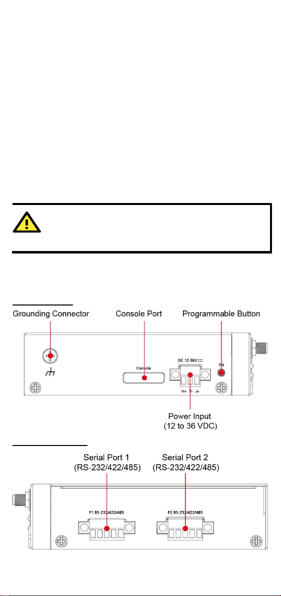
UC-8100A-ME-T Panel Layout
The following figures show the panel layouts of the UC-8100A-ME-T:
Top Panel View
Bottom Panel View
- 2 -
Page 3
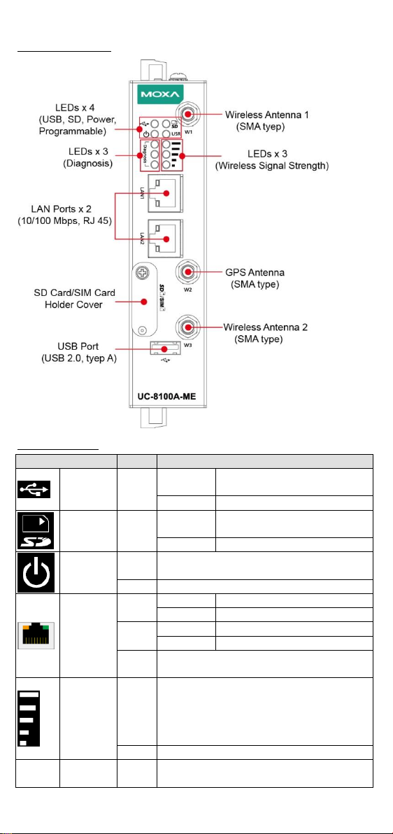
Front Panel View
LED Name
Color
Function
USB
Green
Steady On
USB device is connected and
working normally.
Off
USB device is not connected.
SD
Green
Steady On
SD Card inserted and working
normally.
Off
SD card is not detected.
Power
Green
Power is on and the computer is working
normally.
Off
Power is off.
LAN1/
LAN 2
(RJ45
connector)
Green
Steady On
100 Mbps Ethernet link
Blinking
Data transmission in progress
Yellow
Steady On
10 Mbps Ethernet link
Blinking
Data transmission in progress
Off
Ethernet is not connected.
Wireless
Signal
Strength
Green
Yellow
Red
The number of glowing LEDs indicates the
signal strength.
3 (Green + Yellow + Red): Excellent
2 (Yellow + Red): Good
1 (Red): Poor
Off
Wireless module is not detected.
USR
Userdefined
Green
This LED can be defined by users. For
details, refer to Hardware User’s Manual.
LED Indicators
- 3 -
Page 4

LED Name
Color
Function
Programm
able
diagnostic
LEDs
Green
Yellow
Red
These three LEDs are programmable. For
details, refer to the “Default Programmable
Button Operation" section in the Hardware
User’s Manual.
Input Current
500 mA @ 12 VDC
Input Voltage
12 to 36 VDC (3-pin terminal block,
V+, V-, SG)
Power Consumption
6 W (without cellular module and
external USB device attached)
Operating Temperature
Without LTE Module preinstalled:
-40 to 85°C (-40 to 185°F)
With LTE Module preinstalled:
-40 to 70°C (-40 to 158°F)
Storage Temperature
-40 to 85°C (-40 to 185°F)
1. Pull down the bottom slider
of the DIN-rail bracket
located at the back of the
unit
2. Insert the top of the DIN rail
into the slot just below the
upper hook of the DIN-rail
bracket.
3. Latch the unit firmly on to
the DIN rail as shown in the
illustrations below.
4. Push the slider back into
place.
Specifications
Installing the UC-8100A-ME-T
DIN-rail Mounting
The aluminum DIN-rail attachment plate is already attached to the
product’s casing. To mount the UC-8100A-ME-T on to a DIN rail, make
sure that the stiff metal spring is facing upwards and follow these steps.
- 4 -
Page 5

Wall Mounting (Optional)
Step 1
Use four screws to fasten the
wall-mounting brackets on the
left panel of the computer.
Step 2
Use another four screws to mount
the computer on a wall or a
cabinet.
SG:
The Shielded Ground (sometimes called
Protected Ground) contact is the top contact of
the 3-pin power terminal block connector when
viewed from the angle shown here. Connect the
SG wire to an appropriate grounded metal
surface.
Pin
Signal
1
Tx+ 2 Tx- 3 Rx+ 6 Rx-
The UC-8100A-ME-T can be mounted with a wall-mounting kit that needs
to be purchased separately. Follow these steps to mount the computer on
to a wall:
Connector Description
Power Connector
Connect the power jack (in the package) to the UC-8100A-ME-T’s DC
terminal block (located on the top panel), and then connect the power
adapter. It takes about 30 seconds for the system to boot up. Once the
system is ready, the Power LED will light up.
Grounding the UC-8100A-ME-T
Grounding and wire routing help limit the effects of noise due to
electromagnetic interference (EMI).
Ethernet Ports
The two 10/100 Mbps Ethernet ports (LAN 1 and LAN 2) use RJ45
connectors.
Serial Ports
The two serial ports (P1 and P2) use terminal connectors. Each port can
be configured by software for RS-232, RS-422, or RS-485. The pin
assignments for the ports are shown in the following table:
- 5 -
Page 6

Pin
RS-232
RS-422
RS-485
1
TXD
TXD+
– 2 RXD
TXD-
– 3 RTS
RXD+
D+
4
CTS
RXD-
D-
5
GND
GND
GND
SD/SIM Card Sockets
Pin
Signal
1
TxD 2 RxD 3 NC 4 GND
There are three antenna connectors on
the front panel of the UC-8100A-ME-T.
W1 and W3 are for cellular modules, and
W2 is for the GPS module. All three
connectors are of SMA type.
The UC-8100A-ME-T comes with an SD socket for storage expansion, and
a SIM card socket for cellular communication. The SD card/SIM card
sockets are located at the lower part on the front panel. To install the
cards, remove the screw and the protection cover to access the sockets,
and then insert the SD card or the SIM card into the sockets directly. You
will hear a click when the cards are in place. To remove the cards, push
the cards in before releasing them.
Console Port
The console port is an RS-232 port that can be connected to with a 4-pin
pin header cable. You can use this port for debugging or firmware
upgrade.
USB Port
The USB 2.0 port is located at the lower part of the front panel and
supports a USB storage device driver. By default, the USB storage is
mounted at /mnt/usbstorage.
Antenna Connectors
- 6 -
Page 7

Real-time Clock
ATTENTION
There is a risk of explosion if the battery is replaced with an
incorrect type of battery.
ATTENTION
Remember to choose the “VT100” terminal type. Use the console
cable to connect a PC to the UC-8100A-ME-T's serial console port
Default IP Address
Netmask
LAN 1
192.168.3.127
255.255.255.0
LAN 2
192.168.4.127
255.255.255.0
The real-time clock in the UC-8100A-ME-T is powered by a lithium battery.
We strongly recommend that you do not replace the lithium battery
without the help of a Moxa support engineer. If you need to change the
battery, contact the Moxa RMA service team.
Accessing the UC-8100A-ME-T Using a PC
You can use a PC to access the UC -8100A-ME-T by one of the following
methods:
A. Through the serial console port with the following settings:
Baudrate=115200 bps, Parity=None, Data bits=8, Stop bits =1,
Flow Control=None
B. Using SSH over the network. Refer to the following IP addresses and
login information:
Login: moxa
Password: moxa
- 7 -
 Loading...