

Page 1

P/N: 1802081121013
Technical Support Contact Information
www.moxa.com/support
2021 Moxa Inc. All right s reserved.
UC-8100A-ME-T Series
Quick Installation Guide
Version 3.1, January 2021
*1802081121013*
Page 2
Overview
IMPORTANT!
Notify your sales representative if any of the above items are
missing or damaged.
ATTENTION
Use 16
wiring for connections to
V+, V
wire size should be the same.
The UC-8100A-ME-T computing platform is designed for embedded data
acquisition applications. The UC-8100A-ME-T computer comes with two
RS-232/422/485 serial ports and dual 10/100 Mbps Ethernet LAN ports,
as well as a Mini PCIe socket to support cellular modules. These versatile
communication capabilities let users efficiently adapt the UC-8100A-ME-T
to a variety of complex communic ations solutions.
Package Checklist
Before installing the UC-8100A-ME-T, verify that the package contains
the following items:
• UC-8100A-ME-T embedded computer
• Power jack
• Console cable
• Quick installation guide (printed)
• Warranty card
UC-8100A-ME-T Panel Layout
The following figures show the panel layouts of the UC-8100A-ME-T:
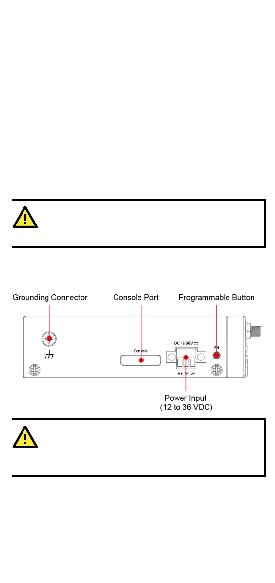
Top Panel View
-24 AWG (1.318 to 0.205 mm2)
-, and GN. Both the power input and earthing conductor
- 2 -
Page 3
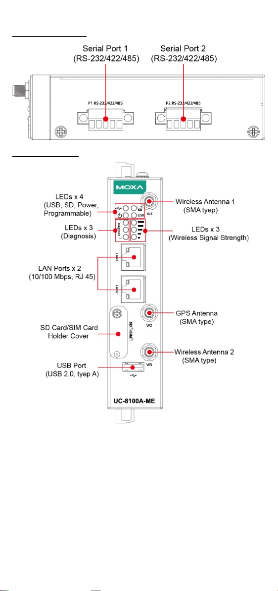
Bottom Panel View
Front Panel View
- 3 -
Page 4

LED Indicators
LED Name
Color
Function
Steady On
USB device is connected and
working normally.
Off
USB device is not connected.
Steady On
SD Card inserted and
working normally.
Off
SD card is not detected.
Power is on and the computer is working
nor m a l l y.
Off
Power is off.
Steady On
100 Mbps Ethernet link
Blinkin g
Data transmission in
progress
Steady On
10 Mbps Ethernet link
Blinkin g
Data transmission in
progress
Off
Ethernet is not connected.
The number of glowing LEDs indicates
1 (Red): Poor
Off
Wireless module is not detected.
Manual.
Programmable
These three LEDs are programmable.
section in the Hardware User’s Manual.
Model
UC-8112A-ME-T-LX
Input Current
700 mA @ 12 VDC
Input Voltage
12 to 36 VDC (3-pin terminal block, V+, V-, SG)
Power Consumption
6 W (without cellular module and external USB
device attached)
Operating
-40 to 70°C (-40 to 158°F)
Storage Temperature
-40 to 85°C (-40 to 185°F)
ATEX Information
USB Green
SD Green
Power
LAN1/LAN 2
(RJ45
connector)
Wireles s
Signal
Strength
USR User-defined Green
diagnostic
LEDs
Green
Green
Yel lo w
Green
Yel lo w
Red
Green
Yel lo w
Red
Specifications
the signal strength.
3 (Green + Yellow + Red): Excellent
2 (Yellow + Red): Good
This LED can be defined by users. For
details, refer to Hardware User’s
For details, refer to the “Default
Programmable Button Operation"
Temperature
Without LTE module pre insta lled:
-40 to 85°C (-40 to 185°F)
With LTE module preinsta lled:
Certificate Number: DEMKO 19 ATEX 2295X
Certification String: Ex nA IIC T4 Gc
Ambient Range: -40°C ≦ Tamb ≦ 85°C
(without LTE module preinstalled)
Ambient Range: -40°C ≦ Tamb ≦ 70°C (with
LTE module preinstalled)
Rated Cable Temp ≧ 90°C
- 4 -
Page 5

IECEx Certificate no.
IECEx UL 19.0107X
Address of
Manufacturer
No. 1111, Heping Rd., Bade Dist., Taoyuan City
334004, Taiwan
Hazardous Location
EN 60079-0:2012+A11:2013/IEC 60079-0 Ed.6
EN 60079-15:2010/IEC 60079-15 Ed.4
Installing the UC-8100A-ME-T
1. Pull down the bottom slider of the DIN-rail
nit firmly on to the DIN rail as shown
Step 1
Use four screws to fasten the
wall
left panel of the computer.
Step 2
Use another four screws to mount
the computer on a wall or a cabinet.
DIN-rail Mounting
The aluminum DIN-rail attachment plate is already attached to the
product’s casing. To mount the UC-8100A-ME-T on to a DIN rail, make
sure that the stiff metal spring is facing upwards and follow these steps.
bracket located at the back of the unit
2. Insert the top of the DIN rail into the slot just
below the upper hook of the DIN-rail bracket.
3. Latch the u
in the illustrations below.
4. Push the slider back into place.
Wall Mounting (Optional)
The UC-8100A-ME-T can be mounted with a wall-mounting kit that needs
to be purchased separately. Follow these steps to mount the computer on
to a wall:
-mounting brackets on the
- 5 -
Page 6

Connector Description
WARNING
EXPLOSION HAZARD!
Do not disconnect equipment unless the power has been
removed or the area is known to be non-hazardous.
SG:
The Shielded Ground (sometimes called
Protected Ground) contact is the
contact of
the 3-pin power terminal block connector when
viewed from the angle shown here. Connect the
SG wire to an appropriate grounded metal
surface.
Pin
Signal
1
Tx+ 2 Tx- 3 Rx+ 6 Rx-
Pin
RS-232
RS-422
RS-485
1
TXD
TXD+
– 2 RXD
TXD-
– 3 RTS
RXD+
D+
4
CTS
RXD-
D-
5
GND
GND
GND
Power Connector
Connect the power jack (in the package) to the UC-8100A-ME-T’s DC
terminal block (located on the top panel), and then connect the power
adapter. It takes about 30 seconds for the system to boot up. Once the
system is ready, the Power LED will light up.
Grounding the UC-8100A-ME-T
Grounding and wire routing help limit the effects of noise due to
electromagnetic interference (EMI).
top
Ethernet Ports
The two 10/100 Mbps Ethernet ports (LAN 1 and LAN 2) use RJ45
connectors.
Serial Ports
The two serial ports (P1 and P2) use terminal connectors. Each port can
be configured by software for RS-232, RS-422, or RS-485 mode. The pin
assignments for the ports are shown in the following table:
SD/SIM card Sockets
The UC-8100A-ME-T comes with an SD socket for storage expansion, and
a SIM card socket for cellular communication. The SD card and SIM card
sockets are located at the lower part on the front panel. T o install the
cards, remove the screw and the protection cover to access the socket,
and then insert the SD card or the SIM card into the sockets direct ly. You
will hear a click when the cards are in place. To remove the cards, push
the cards in before releasing them.
- 6 -
Page 7

Pin
Signal
1
TxD 2 RxD 3 NC 4 GND
There are three antenna connectors on
the front panel of the UC
W1 and W3 are for cellular modules, and
W2 is for
connectors are of
ATTENTION
There is
incorrect type of battery.
Console Port
The console port is an RS-232 port that can be connected to a 4-pin pin
header cable. You can use this port for debugging or firmware upgrade.
USB Port
The USB 2.0 port is located at the lower part of the front panel and
supports a USB storage device driver. By default, the USB storage is
mounted at
/mnt/usbstorage.
Antenna Connectors
-8100A-ME-T.
the GPS module. All three
SMA type.
Real-time Clock
The real-time clock in the UC-8100A-ME-T is powered by a lithium battery.
We strongly recommend that you do not replace the lithium battery
without the help of a Moxa support engineer. If you need to change the
battery, contact the Moxa RMA service team.
a risk of explosion if the battery is replaced with an
- 7 -
Page 8

Accessing the UC-8100A-ME-T Using a PC
ATTENTION
Remember to choose the “VT100” terminal type. Use the console
cable to connect a PC to the UC-8100A-ME-T's serial console port
Default IP Address
Netmask
LAN 1
192.168.3.127
255.255.255.0
LAN 2
192.168.4.127
255.255.255.0
ATTENTION
•
equipment shall only be used in an area of not more than
•
ssible only by the
•
type devices that are to be installed
•
•
HAZARDOUS LOCATIONS MUST BE INSTALLED WITHIN THE
UNCLASSIFIED LOCATION, ROUTING AND INSTALLATION OF
ORDANCE WITH NATIONAL
•
hazardous location.
You can use a PC to access the UC-8100A-ME-T by one of the following
methods:
A. Through the serial console port with the following settings:
Baudrate=115200 bps, Parity=None, Data bits=8, Stop bits =1,
Flow Control=None
B. Using SSH over the network. Refer to the following IP addresses and
login information:
Login: moxa
Password: moxa
The
pollution degree 2, as defined in IEC/EN 60664-1.
The equipment shall be installed in an enclosure that
provides a degree of protection not less than IP 54 in
accordance with IEC/EN 60079-15 and acce
use of a tool.
These devices are open-
in an enclosure with tool removable cover or door, suitable
for the environment.
This equipment is suitable for use in Class I, Divis ion 2,
Groups A, B, C, and D or non-hazardous locations only.
ANTENNAS INTENDED FOR USE IN CLASS I, DIV ISION 2
END-USE ENCLOSURE. FOR REMOTE MOUNTING IN AN
THE ANTENNAS SHALL BE IN ACC
ELECTRICAL CODE REQUIREMENTS (NEC/CEC) Sec.
501.10(b).
The “USB, RS-232/422/485 serial ports, LAN1, LAN2, and
Console ports” and Reset Button may only be accessed for
equipment set-up, installation, and maintenance at a
non-hazardous location. These ports and their associated
interconnect ing cables must rema in inaccessible within the
- 8 -
 Loading...