

Page 1

P/N: 1802081000014
Technical Support Contact Information
www.moxa.com/support
2021 Moxa Inc. All rights reserved.
UC-8100 Series
Quick Installation Guide
Version 4.1, January 2021
*1802081000014*
Page 2
Overview
Top
Bottom
The UC-8100 computing platform is designed for embedded
data-acquisition application s. The computer comes with one or two
RS-232/422/485 serial ports and dual 10/100 Mbps Ethernet LAN ports,
as well as a Mini PC Ie socket to support cellular modules. These versatile
communication capabilities let users efficiently adapt the UC-8100 to a
variety of complex communication solutions.
Package Checklist
• UC-8100 embedded computer
• Console cable
• Power jack
• 3-pin ter minal block for power (preinsta lled)
• 5-pin terminal block for UART x 2 (preinstalled)
Please notify your sales representative if any of the above items are
missing or damaged.
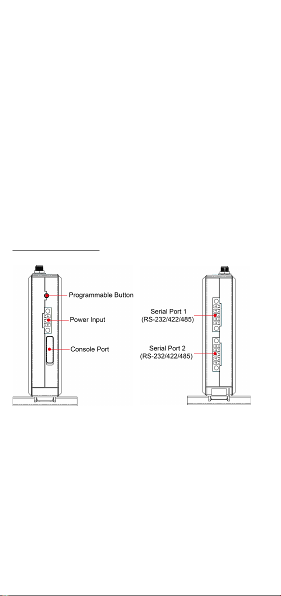
Panel Layout
The following figures show the panel layouts of the UC-8100.
Top and Bottom Panel
- 2 -
Page 3
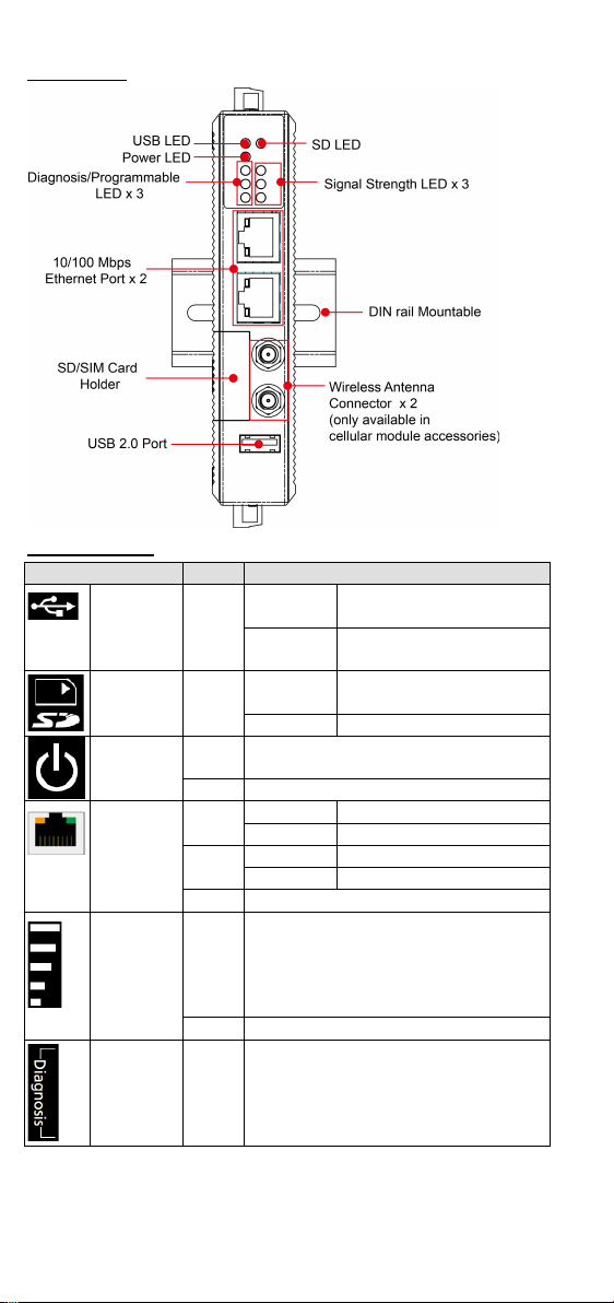
Front Panel
LED Name
Color
Function
USB
Green
Steady On
USB device is connected
and working normally
Off
USB device is not
connected.
working normally
Off
SD card is not detected
Power
Green
Power is on and the computer is
working normally.
Off
Power is off.
LAN1/2
Green
Steady On
100 Mbps Ethernet link
Blinkin g
Data transmitting
Yel lo w
Steady On
10 Mbps Ethernet link
Blinkin g
Data transmitting
Off
Ethernet is not connected
1 (Red): Poor
Off
Wireles s modu le is not detected
Diagnosis
Green
These 3 LEDs are used for diagnostics
LED Indicators
SD Green Steady On SD Card inserted and
(On RJ45
connector)
Number of glowing LEDs indicates
Wireles s
Signal
Strength
Green
signal strength
Yel lo w
3 (Green + Yellow + Red): Excellent
Red
2 (Yellow + Red): Good
Yel lo w
and are programmable. For additional
Red
details, refer to the UC-8100 Series
Hardware Manual.
- 3 -
Page 4

Installing the UC-8100
Pull out both the top and bottom
sliders,
mounting holes, and secure the
dev
screws into the wall
There are two sliders on the back of the unit for DIN-rail an d wall
mounting.
Mounting on a DIN Rail
Pull out the bottom slider, latch the unit onto the DIN rail, and push the
slider back in.
Mounting on a Wall
align the screws with the
ice to the wall by driving the
Another method for wall mounting installation is to use the optional wall
mounting kit. Attach two mounting brackets on the side panel of the
computer, and fasten with screws. Install the computer on to a wall or
cabinet by fastening two screws for each mounting bracket.
.
Connector Description
Power Connector
Connect the “terminal block to power jack converter” (included in the
package) to the UC-8100’s DC terminal block (located on the top panel),
and then connect the power adapter. It takes about 30 seconds for the
system to boot up. Once the system is ready, the Power LED will light up.
- 4 -
Page 5

Grounding the UC-8100
SG: The s
ground (sometimes called
p
contact of the 3
block connector when viewed from the
angle shown here. Connect the SG wire
to an appropriate grounded metal
surface.
ATTENTION
The product is intended to be supplied by an UL Listed power
adapter whose output meets SELV/LPS, and is rated 12-24 VDC,
minimum 0.5 A, Tma = 85°C (minimum).
Pin
Signal
1
ETx+ 2 ETx-
3
ERx+ 6 ERx-
Pin
RS-232
RS-422
RS-485
1
TXD
TXD+
– 2 RXD
TXD-
– 3 RTS
RXD+
D+
4
CTS
RXD-
D-
5
GND
GND
GND
Grounding and wire routing help limit the effects of noise due to
electromagnetic interference (EMI).
hielded
rotected ground) contact is the top
-pin power terminal
Ethernet Ports
The two 10/100 Mbps Ethernet ports (LAN 1 and LAN 2) use RJ45
connectors. Refer to the following table for the pin assignments.
Serial Ports
The two serial ports (P1 and P2) use terminal connectors. Each port can
be configured by software for RS-232, RS-422, or RS-485. Refer to the
following table for the pin assignments.
SD/SIM Card Slots
The UC-8100 comes with an SD slot for storage expansion and a SIM card
slot for cellular communication. The SD card/SIM card slots are located at
the lower part of the front panel. To install them, remove the screw and
the cover to access the slots, and then insert the SD card or the SIM card.
You will hear a click when they are inserted correctly. To remove them,
push the cards in and then release them.
- 5 -
Page 6

Console Port
Pin
Signal
1
TxD 2 RxD 3 NC 4 GND
ATTENTION
There is
incorrect type of battery.
The console port is a RS-232 port that can be connected with a 4-pin pin
header cable. You may use this port for debugging or firmware upgrade.
USB
The USB 2.0 port is located at the lower part of the front panel, and
supports a USB storage device driver.
Real-time Clock
The UC-8100’s real-time clock is powered by a non-chargeable battery.
We strongly recommend that you do not replace the battery without help
from a qualified Moxa support engineer. If you need to change the battery,
contact the Moxa RMA service team.
a risk of explosion if the battery is replaced by an
Installing the Cellular Module
The UC-8100 provides a Mini PCIe socket for installing a cellular module.
The cellular module package includes the following items.
- 6 -
Page 7

Follow these steps to in stall the cellular module.
1. Unfasten the screws on the side
2. Find the location of the PCIe
3. Remove the plastic plate and the
. Press the thermal
o that it sticks to the
screws to secure the module to
panel of the computer and
remove the cover.
socket.
sticker on both sides of the
large thermal pad and place it
in the socket
pad down s
base of the socket.
Place the thermal pad as close
as possible to the holes for the
screws used to secure the
module.
4. Insert the cellular modu le into
the socket and tighten the
the socket.
- 7 -
Page 8

5. Remove the plastic plate and the
sticker on both side of the
small
6. Install the antenna cables.
on the module; two
for cellular antennas and one for
computer, you can only use two
antennas at a time. You may use
7. Connect one end of the antenna
connector
connector hole before you insert
9. Insert the locking washer
through the connector and press
thermal pad and stick the
thermal pad on to the module.
There are three antenna
connectors
a GPS antenna. Refer to the
figure for details. As there are
only two antenna connector
holes on the front panel of the
two cellular antennas, or a
cellular antenna and a GPS
antenna. The same antenna
cables can be used for both
antenna types.
cable to the cellular module.
8. Insert the other end of the
cable, with the connector,
through the antenna
hole on the front panel of the
computer. Remove the black
plastic protection cover on the
the antenna wire.
it against the cover of the
computer. Then, insert the nut
and tighten it to secure the
connector to the cover.
- 8 -
Page 9

10. Connect the antenna to the
antenna connector.
11.
ATTENTION
Remember to choose the “VT100” terminal type. Use the
CBL
PC
to the UC-8100’s serial console port.
Default IP Address
Netmask
LAN 1
192.168.3.127
255.255.255.0
LAN 2
192.168.4.127
255.255.255.0
Replace the cover of the
computer.
Connecting the UC-8100 to a PC
A. Through the serial console port with the following settings:
Baudrate=115200 bps, Parity=None, Data bi ts=8, Stop bits
=1, Flow Control=None
-RJ45F9-150 cable included in the package to connect the
B. By SSH over the network. Refer to the following IP addresses and
login information.
Login: moxa
Password: moxa
- 9 -
 Loading...