

Page 1

P/N: 1802021000112
Technical Support Contact Information
www.moxa.com/support
Moxa Americas:
Toll
Tel:
Fax:
Moxa China (Shanghai office):
Toll
Tel:
Fax:
Moxa Europe:
Tel:
Fax:
Moxa Asia-Pacific:
Tel:
Fax:
Moxa India:
Tel:
Fax:
2019 Moxa Inc. All rights reserved.
UC-2100 Series
Quick Installation Guide
Version 3.0, March 2019
-free: 1-888-669-2872
1-714-528-6777
1-714-528-6778
+49-89-3 70 03 99-0
+49-89-3 70 03 99-99
+91-80-4172-9088
+91-80-4132-1045
-free: 800-820-5036
+86-21-5258-9955
+86-21-5258-5505
+886-2-8919-1230
+886-2-8919-1231
*1802021000112*
Page 2

Overview
NOTE
The console cable and power jack can be found beneath the
molded pulp cushioning inside the product box.
The UC-2100 Series computing platform is designed for embedded data
acquisition and processing applications. The computer comes with up to
two software-selectable RS-232/422/485 full-signal seria l ports and
single or dual Ethernet LAN ports. In addition, the Arm-based computing
platform is available in various models that can fulfill diverse interface
requirements, such as single and dual serial, LAN ports, and gigabit
Ethernet, and wireless connections. These versatile communication
capabilities let u sers efficiently adapt the palm-sized UC-2100 computing
platfor m to a variety of complex communications solutions.
Model Names and Package Checklist
The UC-2100 Serie s includes the following models:
UC-2101-LX: Palm-sized industrial computing platform with 1 serial p ort,
1 Ethernet port, -10 to 60°C operating temperature
UC-2102-LX: Palm-sized industrial computing platform with 2 Ethernet
ports, -10 to 60°C operating temperature
UC-2104-LX: Palm-sized industrial computing platform with 1 Min i PCIe
socket for wireless module, 1 Ethernet port, -10 to 70°C operating
temperature
UC-2111-LX: Palm-sized industrial computing platform with 2 serial
ports, 2 Ethernet ports, Micro SD socket, -10 to 60°C operating
temperature
UC-2112-LX: palm-sized industrial computer with 1 GHz processor, 2
serial ports, 2 Ethernet ports (1 gigabit Ethernet), Micro SD socket, -10 to
60°C operating temperature
UC-2112-T-LX: Palm-sized indust rial computing platform with 1 GH z
processor, 2 serial ports, 2 Ethernet ports (1 gigabit Ethernet), Micro SD
socket, -40 to 75°C operating temperature
Before installing a UC-2100 computer, verify that the package contains
the following ite ms:
• UC-2100 Series computer
• Console cable
• Power jack
• Quick Installation Guide (printed)
• Warranty card
Notify your sales representative if any of the above items are missing or
damaged.
- 2 -
Page 3
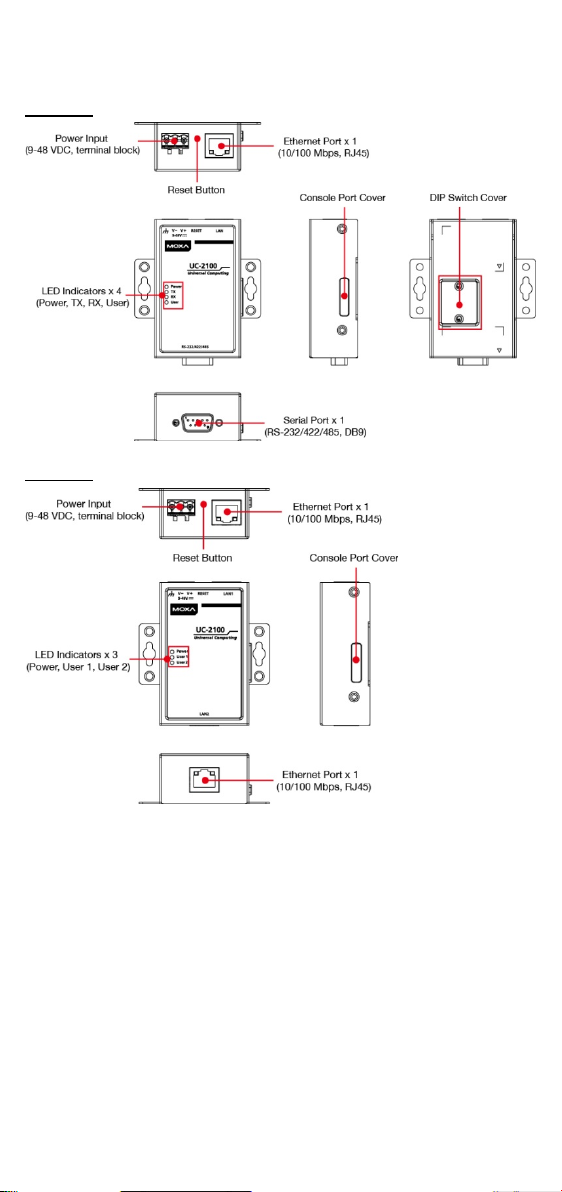
Appearance
UC-2101
UC-2102
- 3 -
Page 4
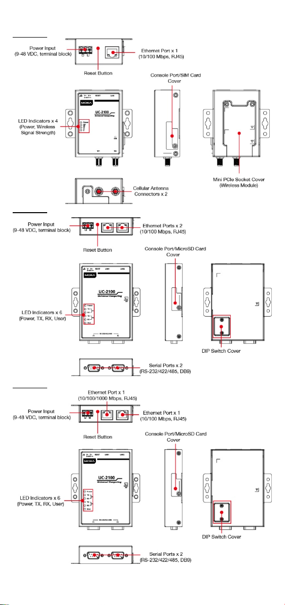
UC-2104
UC-2111
UC-2112
- 4 -
Page 5
LED Indicators
LED Name
Status
Function
Green
Power is on, and the device is functioning
normally
Off
Power is off
Green
Steady On: 10 Mbps Ethernet link
Blinkin g: Data transmission is in progress
Yel lo w
Steady On: 100 Mbps Ethernet link
Blinkin g: Data transmission is in progress
Off
Speed lower than 10 Mbps or the cable is
not connected
Green
only)
Steady On: 100 Mbps Ethernet link
Yel lo w
only)
Steady On: 1000 Mbps Ethernet link
Green
Serial port is transmitting data
Off
Serial port is not transmitting data
Yel lo w
Serial port is rece iving data
Off
Serial port is not receiving data
User
Green/Yellow
User Programmable
LEDs that
strength
Yel lo w
The number of glowing LEDs indicates
1 LED : Poor
Off
Wireless module is not detected
The function of each LED is described in the table below:
Power
Ethernet
(UC-2112
Blinkin g: Data transmission is in progress
(UC-2112
Serial (Tx)
Serial (Rx)
indicate
the
Wireless
signal
Blinkin g: Data transmission is in progress
the signal strength
3 LEDs: Excellent
2 LEDs : Good
Reset Button
The UC-2100 panel computer is provided with a reset button, which is
located on the top panel of the computer. To reboot the computer, press
the reset button for 1 second. Press and hold the reset button between 7
to 9 seconds to reset the computer to the factory default settings. When
the reset button is held down, the User LED (the first signal LED on
UC-2104) will blink once every second. The User LED will become steady
when you hold the button continuously for 7 to 9 seconds. Release the
button within this period to load the factory default sett ings.
Installing the Computer
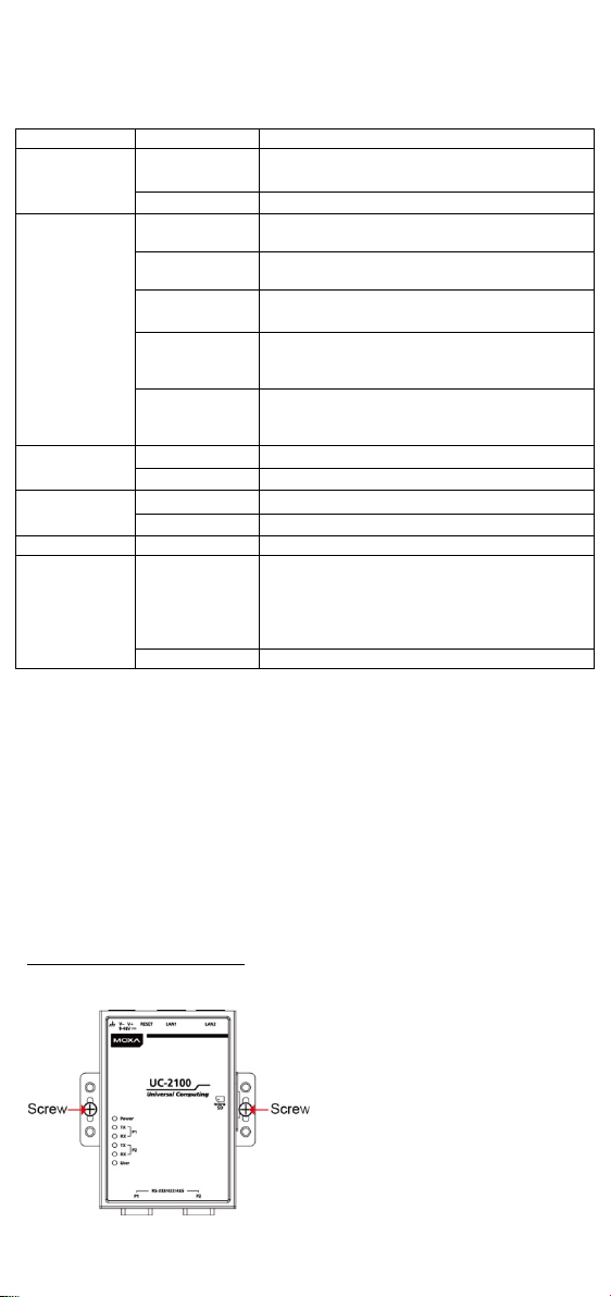
Wall or Cabinet Mounting
Use two screws per side to mount the UC-2100 Series on a wall or inside
a cabinet.
- 5 -
Page 6

Wiring Requirements
NOTE
Do not run signal or communication wiring and power wiring in
the same wire conduit. To avoid interference, wires with different
signal characteristics should be routed separately.
ATTENTION
This equipment i
Locations.
Safety First!
Be sure to disconnect the power cord before installing and/or
wiring your
Wiring Caution!
Calculate the maximum possible current in each power wire and
common
maximum current allowable for each wire size. If the current
goes above the maximum ratings, the wiring could overheat,
causing serious damage to your equipment.
CAUTION
Be careful when handling the uni
the internal components generate heat, and consequently the
outer casing may feel hot to the touch.
Connect the 9 to 48 VDC power line to the terminal
Input Rating: 9 to 48 VDC, 0.45 to 0.084 A
Be sure to read and follow these common safety precautions before
proceeding with the installation of any electronic device:
• Use separate paths to route wiring for power and devices. If power
wiring and device wiring paths must cross, make sure the wires are
perpendicular at the intersection point.
• Use the type of signal transmitted through a wire to determine which
wires should be kept separate. The rule of thumb is that wiring that
shares similar electrical characteristics can be bundled together.
• Keep input wiring and output wiring separate.
• It is strongly advised that you label wiring to all devices for easy
identification.
s intended to be used in Restricted Access
UC-2100 Series computers.
wire. Observe all electrical codes dictating the
t. When the unit is plugged in,
Connecting the Power
block, which is connected to the UC-2100 Series
computer. If the power is supplied properly, the
“Power” LED will glow a solid green light. The power
input location and pin definition are shown in the
adjacent diagram. The input terminal block (CN5) is
suitable for a wire size of 12 to 30 AWG (3.3 to 0.05
2
mm
) and a torque value of 0.5 N-m (4.425 lb-in).
- 6 -
Page 7

Grounding the Unit
Serial Console Port & Pinouts
Serial Console Cable
Pin
Signal
1
TxD 2 RxD 3 NC 4 GND
The LED indicator on the upper
right corner glows a solid green
color when the
establishes a connection with a
100 Mbps Ethernet network.
The
when Ethernet packets
being transmitted or received.
Pin
Signal
1
ETx+ 2 ETx-
3
ERx+ 4 – 5 – 6 ERx- 7 – 8 –
The LED indicator in the upper
left corner glows a solid orange
color when the
establishes a connection with a
10 Mbps Ethernet network.
The
when Ethernet packets
being transmitted or received.
Grounding and wire routing help limit the effects of noise due to
electromagnetic interference (EMI). Run the ground connection from the
terminal block connector to the grounding surface prior to connecting the
power. Please note that this product is intended to be mounted on a
well-grounded mounting surface, such as a metal panel. The minimum
cross-sectional area of the earthing conductor shall be equal to the input
wiring cable.
Connecting to the Console Port
The UC-2100 console port is a 4-pin pin-header RS-232 port located on
the right panel of the case. It is designed for serial console terminals,
which are useful for viewing the boot up message, or for debugging
system boot up issues. Remove the protective cover on the port to
connect the console cable.
Connecting to the Network
The Ethernet ports are located on the top or bottom panel of the UC-2100
computers. The pin assignments for the Ethernet port are shown in the
following figure. If you are u sing your o wn ca ble, make sure that the pin
assignments on the Ethernet cable connector match the pin assignments
on the Ethernet port.
computer
LED will flash on and off
LED will flash on and off
computer
- 7 -
are
are
Page 8

For the UC-2112 model, refer to the following detaile d pin definitions for
The LED indicator in the upper
left
green
color when the
establishes a connection with
a 100 Mbps Ethernet network.
The
when Ethernet packets
being transmitted or received.
Pin
Signal
1
MDI0+
2
MDI0-
3
MDI1+
4
MDI2+
5
MDI2-
6
MDI1-
7
MDI3+
8
MDI3-
The LED indicator in the upper
right
orange color when
computer establishes a
connection with a
Ethernet network. The LED will
flash on and off when Ethernet
packets are being transmitted
or received.
The serial ports are located on the bottom panel
RS-485
(4-wire)
RS-485
(2-wire)
1
DCD
TxDA(-)
TxDA(-)
– 2 RxD
TxDB(+)
TxDB(+)
– 3 TxD
RxDB(+)
RxDB(+)
DataB(+)
4
DTR
RxDA(-)
RxDA(-)
DataA(-)
5
GND
GND
GND
GND 6 DSR – – – 7
RTS – – – 8
CTS – –
–
the gigabit Ethernet port.
corner glows a solid
LED will flash on and off
corner glows a solid
computer
are
the
1000 Mbps
Connecting to a Serial Device
of the UC-2100 computer. Use a serial cable to
connect your serial device to the computer’s
serial port. These serial ports have male DB9
connectors and can be configured for RS-232,
RS-422, or RS-485 communication. The pin
location and assignments are shown in the
following table.
Pin RS-232 RS-422
- 8 -
Page 9

Connecting the Cellular/Wi-Fi Module and Antenna
1. Set the antenna cables
The UC-2104 computer comes with one Mini PCIe socket for installing one
cellular or Wi-Fi module. Unfasten the two screws on the rear panel and
one screw on the bottom panel to remove the cover and find the location
of the socket.
The cellular module packa ge includes 1 cellular module and 2 screws. The
cellular antennas should be purchased separately to fit your installation
requirements.
Follow these steps to install the cellular module.
aside and clear the
wireless module socket as
shown in the figure for
convenience of installation.
2. Insert the cellular module
into the socket and fasten
two screws (in the
package) on to the top of
the module
3. Connect the free ends of
the two antenna cables
next to the screws as
shown in the image.
- 9 -
Page 10

4. Replace the cover and
secure it using the three
or removing the module)
5. Antenna connectors are
screws.
(Use of a tweezer is
recommended when installing
located on the top panel of
the computer. Connect the
cellular antennas to the
connectors.
The Wi-Fi module package includes 1 Wi-Fi module and 2 screws. The
antenna adapters and Wi-Fi antennas should be purchased separately to
fit your installation requirements.
- 10 -
Page 11

Follow these steps to install a Wi-Fi module.
1. Set the antenna cables
2. Insert the Wi-Fi module
removing the module)
5. Connect the antenna
6. Connect the Wi-Fi
2. Insert the SIM card into the
release it.
aside and clear the
wireless module socket as
shown in the figure for
convenience of installation.
into the socket and fasten
the two screws (in the
package) on to the top of
the module.
3. Connect the free ends of
the two antenna cables
next to the screws as
shown in the image.
4. Replace the cover and
secure it with the three
screws.
(We recommend using a
tweezer when installing or
adapters to the connectors
on the top panel of the
computer.
antennas to the antenna
adapters.
Installing SIM Cards
You will need to install a SIM card on your UC-2104 computer. Follow
these steps to install the SIM card.
1. Remove the screw on the
cover located on the right
panel of the UC-2104.
socket. Make sure you place
the chip-side on the bottom.
3. To remove the SIM card,
simply push the SIM card and
- 11 -
Page 12

Installing the MicroSD Card
1. The MicroSD socket is
cover.
2. Insert the MicroSD card into
release it.
1. Remove the screws on the DIP
is OFF.
Both UC-2111 and UC-2112 Series come with a storage socket that allows
users to install one MicroSD card. Follow these steps to install the MicroSD
card:
located below the right
panel of the computer.
Unfasten the screw and
remove the right panel
the socket.
Ensure that the card is
inserted in the right
direction.
3. Replace the cover and
fasten the screw on the
cover to secure the cover.
To remove the MicroSD card,
simply push the card in an d
Adjusting the DIP Switch
The UC-2101, UC-2111, and UC-2112 Series computers come with
one DIP switch for users to adjust the serial port parameters. To set
up the DIP switch, do the following:
switch cover located on the rear
panel of the computer.
2. Remove the thin film on the DIP
switch and adjust the setting as
required.
Refer to the table below for the DIP
switch settings. The default value
SW 1 2 3 4
Low High Term. N/A
1KΩ 1KΩ 120Ω
ON
150KΩ 150KΩ
OFF
N/A
N/A N/A
- 12 -
Page 13

ATEX
Information
IECEx Certificate
no.
IECEx UL 18.0093X
Manufacturer’s
Address
FI.4, No.135, Lane 235, Baoqiao Road,
Xindian District, New Taipei City, Taiwan
Hazardous
Certifications
EN 60079-0:2012+A11:2013/IEC 60079-0:2011
EN 60079-15:2010/IEC 60079-15:2010 Ed.4
Temperature
Code (T-code)
T4
ATTENTION
• The equipment shall only be used in an area of not more than
•
15 and accessible only by the
•
type devices that are to be installed
•
Groups A, B, C, and D or non-hazardous locations only
WARNING
EXPLOSION HAZARD!
Do not
is
FREE OF IGNITIBLE CONCENTRATIONS.
II 3 G
DEMKO 18 ATEX 2087X
Ex nA IIC T4 Gc
Ambient Range : -10 °C ≦ Ta m b ≦ 60 °C (For
UC-2112-YY-ZZZZZ models)
Ambient Range : -40 °C ≦ Ta m b ≦ 75 °C (For
UC-2112-T-YY-ZZZZZ models)
Rated Cable Temp ≧ 83.9 °C
Location
Ed.6
pollution degree 2, as defined in IEC/EN 60664-1.
The equipment shall be installed in an enclosure that
provides a degree of protection not less than IP 54 in
accordance with IEC/EN 60079use of a tool.
These devices are open-
in an enclosure with tool removable cover or door, suitable
for the environment.
This equip ment is suitable for use in C lass I, Division 2,
DISCONNECT WHILE CIRCUIT IS LIVE unless the area
- 13 -
Page 14

CAUTION
Risk of explo sion if battery is rep laced by an incorrect t ype.
Dispose of used batteries according to local regulations.
IMPORTANT!
Equipment is intended to be supplied by an UL Listed external
power supply, whose output meets SELV and LPS and is rated at
9 to 48 VDC, minimum 0.45 to 0.084 A, and
minimum Tma = 75
°C.
- 14 -
 Loading...