

Page 1

P/N: 1802058000012
Technical Support Contact Information
www.moxa.com/support
2021 Moxa Inc. All rights reserved.
TN-5816A/5818A Series
Quick Installation Guide
Moxa ToughNet Switch
Version 2.1, January 2021
*1802058000012*
Page 2

Overview
The ToughNet TN-5816A/5818A switches are high performance M12
Layer 3 Ethernet switches that support Layer 3 routing functionality to
facilitate the deployment of applications across networks.
TN-5816A/5818A switches use M12 and other circular connectors to
ensure tight, robust connections and guarantee reliable operation against
environmental disturbances, such as vibration and shock.
TN-5816A/5818A switches support isolated power in the 24 to 110 VDC
power input range, allowing the same model to be used at different sites
around the globe. TN-5816A/5818A switches provide up to 16 Fast
Ethernet M12 ports with 2 bypass relay ports, and 2 Ethernet interface
Gigabit ports with bypass relay functionality. Furthermore, with a -40 to
75°C operating temperature and IP54-rated waterproof enclosure, the
switches can be deployed in harsh environments. The TN-5816A/5818A
series Ethernet switches are compliant with mandatory sections of EN
50155, covering operating temperature, power input voltage, surge, ESD,
and vibration, as we ll as conformal coating and power insulation, making
the switches suitable for a variety of industria l applications.
Package Checklist
Your ToughNet TN-5816A/5818A switch is shipped with the following
items. If any of these items is missing or damaged, please contact your
customer service representative for assistance.
• 1 Moxa ToughNet switch
• M12 to DB9 console port cable
• 2 protective caps for console and relay output ports
• Panel mounting kit
• CD-ROM with user’s manual, Windows utility, and SNMP MIB file
• Quick in stallation guide (printed)
• Warranty card
Features
Anti-Vibration Circular Connectors for Robust Links
• M12 D-coding 4-pin female connectors for Fast Ethernet
10/100BaseT(X) ports.
• M12 X-coded 8-pin connector for Gigabit Ethernet
10/100/1000BaseT(X) ports
• M12 A-coding 5-pin male connectors for console and relay output.
• M23 6-pin male connector for power input.
Dual Isolated Power Inputs
• 24 to 110 VDC (16.8 to 137.5 VDC), isolated.
Designed for Industry-specific Applications
• Two Gigabit Ethernet ports to meet high bandwidth requirements.
• Bypass relay ensures non-stop data communication in the event the
switch stops working due to a power failure.
• Complies with all EN 50155 mandatory test items*.
• -40 to 75°C operating temperature range.
• IP54, rugged high-strength case.
• Panel mounting or DIN-rail mounting installation capability.
*This product is suitable for rolling stock railway applications, as defined
by the EN 50155 standard. For a more detailed statement, click here:
www.moxa.com/doc/specs/EN_50155_Compliance.pdf
- 2 -
Page 3

Recommended Optional Accessories
• CBL-M23(FF6P)Open-BK-100-IP67: 1-meter M23 to 6-pin power
cable with IP67-rated female 6-pin M23 connector
• CBL-M12D(MM4P)/RJ45-100 IP67: 1-meter M12-to-RJ45 Cat-5E UTP
Ethernet cable with IP67-rated male 4-pin M12 D-coded connector
• CBL-M12(FF5P)/OPEN-100 IP67: 1-meter M12-to-5-pin power cable
with IP67-rated female 5-pin M12 A-coded connector
• M12D-4P-IP68: F ield-installable M12 D-coded screw-in connector,
male 4-pin, IP68-rated
• M12A-5P-IP68: F ield-installable M12 A-coded screw-in connector,
female 5-pin, IP68-rated
• CAP-M12F-M: Metal cap for M12 female connector
• DK-DC50131: DIN-rail mounting kit, 50 x 131 mm
- 3 -
Page 4
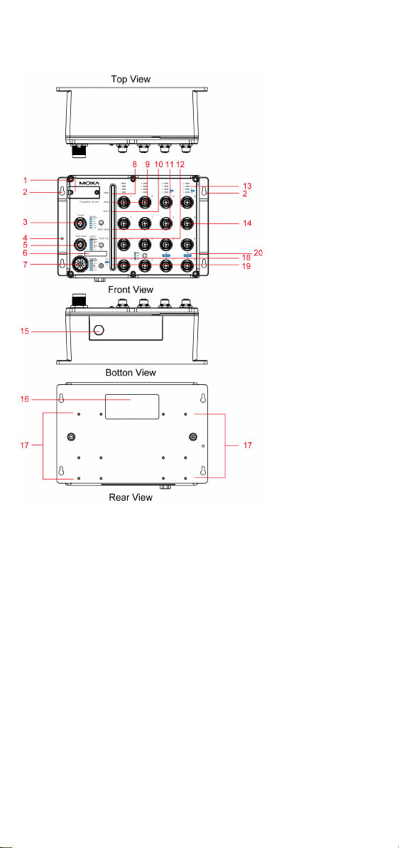
TN-5816A Panel Layouts
1. Model name
10.
11.
12.
13.
14.
pin shielded M12 connector with D
15.
16.
17.
18.
19.
20. Ports 9-10, 13-14 with relay b ypass funct ion
2. Screw holes for panel mounting kit
3. Console port
4. Grounding screw
5. Relay output port
6. Power input voltage range indicator
7. Power input port (male 6-pin shielded M23 connector)
8. PWR1 LED: for power input 1
9. PWR2 LED: for power input 2
FAULT LED
MSTR/HEAD LED: for ring master or chain head
CPLR/TAIL LED: for ring coupler or chain tail
TP port’s 10/100 Mbps LED
10/100BaseT(X) port (female 4-
coding)
Waterproof vent
Product label
12 screw holes for DIN-rail mounting kit
E2 LED: Not used by the TN-5816 series
E1 LED: Not used by the TN-5816 series
- 4 -
Page 5
TN-5818A Panel Layouts
1. Model name
10.
11.
12.
13.
14.
pin shielded M12 connector with D
15.
16.
17.
18. E2 LED: Down-side E2 Gigabit port’s 10/100/1000 Mbps LED
2. Screw holes for panel mounting kit
3. Console port
4. Grounding screw
5. Relay output port
6. Power input voltage range indicator
7. Power input port (male 5-pin shielded M23 connector)
8. PWR1 LED: for power input 1
9. PWR2 LED: for power input 2
FAULT LED
MSTR/HEAD LED: for ring master or chain head
CPLR/TAIL LED: for ring coupler or chain tail
TP port’s 10/100 Mbps LED
10/100BaseT(X) port (female 4-
coding)
Waterproof vent
Product label
12 screw holes for DIN-rail mounting kit
- 5 -
Page 6

19. E1 LED: Down-side E1 Gigabit port’s 10/100/1000 Mbps LED
20.
Gigabit Ethernet port E1 (corresponding to port 17 in the TN-5818
A
21.
A
22. Ports 9-10, 13-14 with relay b ypass funct ion
ATTENTION
DO NOT open or remove the vent (#15). Once the seal has been
removed, the warranty will be
Ports (including 3, 5, and 14) that are not in use must be tightly
covered with protective caps (an optional accessory) to ensure
IP54/IP67
After the rotary switches (1) are set, the protective cover must be
properly affixed to ensure IP54-rated protection.
User's Manual; ports 17-18 support relay bypass function)
Gigabit Ethernet port E2 (corresponding to port 18 in the TN-5818
User’s Manual; ports 17-18 support relay bypass function)
invalid.
-rated protection.
Mounting Dimensions (unit = mm)
TN-5816A Series
- 6 -
Page 7

TN-5818A Series
STEP 2:
U
would like to use your own screws, make sure the
screw head
diameter and the shaft
diameter, as shown
Panel/Wall Mounting
STEP 1:
Mounting the TN-5816A/5818A to a wall requires 4 screws. Use the
ToughNet switch as a guide to mark the correct positions of the 4 screws.
se the 4 screws in the panel mounting kit. If you
is between 6.0 mm and 7.0 mm in
Do not screw the screws in all the way—leave a space of about 2 mm to
allow room for sliding the ToughNet switch between the wall and the
screws.
is less than 4.0 mm in
at the right.
- 7 -
Page 8

NOTE
Before tightening the screws into the wall, make sure the screw
head and shaft size are suitable by inserting the screw through
one of the keyhole-shaped apertures of the ToughNet switch.
STEP 3:
NOTE
To provide greater protection from vibrations and shocks, use
screws with shaft diameter between 6.0 mm and 7.0 mm, and fix
the ToughNet switch onto the wall directly through the large
opening of the keyhole-shaped apertures.
Use the optional DIN-rail mountin g
kit
purchased separately)
mount the
TN
DIN
STEP 1:
per plate) to attach the two DIN-rail
attachment plates to the rear panel
of the switch.
STEP 3:
switch on the DIN
clamps hook over the top edge of the
rail.
STEP 4:
Once the screws are fixed in the wall, hang the ToughNet switch on the 4
screws through the large opening of the keyhole-shaped apertures, and
then slide the switch downwards. Tighten the four screws for added
stability.
DIN-Rail Mounting (optional)
(DK-DC50131, must be
-5816A/5818A on a 35 mm
-rail.
Use 12 screws (6 screws
STEP 2: If the spring-loaded bracket is locked in place, push the recessed
button to release it. Once released, you should feel some resistance from
the spring as you slide the bracket up and down a few millimeters in each
direction.
Position the ToughNet
to
-rail, tilted so the
fully onto the DIN-rail, until both
Swing the switch down
clamps completely latch.
- 8 -
Page 9

To remove the Moxa ToughNet Switch from
the DIN
-rail, use a screw
driver to pull out the
two spring-loaded brackets from the bottom
until they are fix
Then
WARNING
Turn the power off before disconnecting modules
correct power supply voltage is listed on the product label. Check
the voltage of your power source to make sure you are using the
correct voltage. Do NOT use a voltage greater than what is
specified on the product label.
These devices must
the Low Voltage Directive 2006/95/EC and 2004/108/EC.
ATTENTION
Safety First!
Be sure to disconnect the power cord before installing and/or
wiring your Moxa switch.
This de vice
60
to 75°C
degree 2 environments.
ATTENTION
Safety First!
Observe all electrical codes dictating the
allowable for each wire size. If the current
maximum ratings, the wiring could overheat,
damage to your equipment.
, reverse Steps 3 and 4 above.
ed in a “locked” position.
Wiring Requirements
be supplied by a SELV source as defined in
has UL 508 approval. Use copper conductors only,
, and tighten to 4.5 pound-inches. For use in pollution
or wires. The
- 9 -
maximum current
goes above the
causing serious
Page 10

Please Read and Follow These Guidelines:
ATTENTION
This product is intended to be mounted to a well
mounting surface such as a metal panel.
• Use separate paths to route wiring for power and devices. If power
wiring and device wiring paths must cross, make sure the wires are
perpendicular at the intersection point.
NOTE: Do not run signal or communications wiring and power wiring
through the same wire conduit. To avoid interference, wires with
different signal characteristics should be routed separately.
• You can use the type of signal transmitted through a wire to
determine which wires should be kept separate. The ru le of thum b is
that wiring that shares similar electrical characteristics can be
bundled together.
• Keep input wiring and output wiring separated.
• It is strongly advised that you label wiring for all devices in the system
when necessary.
Grounding the ToughNet Switch
Grounding and wire routing help limit the effects of noise due to
electromagnetic interference (EMI). Run the ground connection from the
grounding screw to the grounding surface prior to connecting devices.
-grounded
Connecting the Power Supplies
The ToughNet TN-5816A/5818A series switches support two sets of
power supplies—power input 1 and power input 2. The M23 6-pin male
connector on the TN-5816A/5818A’s front panel is used for the dual
power inputs.
- 10 -
Page 11

Pinouts for the power input port on the TN-5816A/5818A
Pin
Description
Usage
1
PWR1 Live / DC +
Connect “PWR1 Live / DC +” to the positive
(+) terminal when using a DC power source.
2
PWR1 Neutral /
DC -
Connect “PWR1 Neutral / DC –” to the negative
(-) terminal when using a DC power source.
3
Chassis Ground
Connect the “Chassis Ground” to the safety
ground terminal for DC inputs.
4
PWR2 Neutral /
DC -
Connect “PWR2 Neutral / DC –” to the negative
(-) terminal when using a DC power source.
5
PWR2 Live / DC +
Connect “PWR2 Live / DC +” to the positive
(+) terminal when using a DC power source.
ATTENTION
Before connecting the TN
make sure the power source voltage is stable.
STEP 1: Plug the power cord connector into the TN-5816A/5818A’s
power input port.
STEP 2: Screw in the nut on the power cord connector to the power input
connector (on the switch) to ensure a tight connection.
-5816A/5818A to the power input,
Connecting the Relay Outputs
Each TN-5816A/5818A switch has two sets of relay outputs—relay output
1 and relay output 2.The M12 A-coded 5-pin male connector on the
TN-5816A/5818A front panel is used for the two relay outputs. Use a
power cord with an M12 A-coded 5-pin female connector to connect the
relay contacts. You can purchase an M12 power cable from Moxa; the
model number is CBL-M12 (FF5P)/OPEN-100 IP67.
Pinouts for the TN-5816A/5818A’s relay output port
N.C.: Not connected
- 11 -
Page 12

FAULT:
The two sets of relay contacts of the M12 A-coded 5-pin male connector
are used to detect user-configured events. The two wires attached to the
fault contacts form an open circuit when a user-configured event is
triggered. If a user-configured event does not occur, the fault circuit
remains closed.
Connecting the Data Lines
10/100BaseT(X) Ethernet Port Connection
All TN-5816A/5818A models have 16 10/100BaseT(X) Ethernet ports
(4-pin shielded M12 connector with D coding). The 10/100TX ports
located on the TN-5816A/5818A front panel are used to connect to
Ethernet-enabled devices. Most users configure these ports for Auto
MDI/MDI-X mode, in which case the port’s pinouts are adjusted
automatically depending on the type of Ethernet cable used
(straight-through or cross-over), and the type of device (NIC-type or
HUB/Switch-type) connected to the port.
In what follows, we give pinouts for both MDI (NIC-type) ports and MDI-X
(HUB/Switch-type) ports. We also give cable wiring diagrams for
straight-through and cross-over Ethernet cables.
10/100BaseT(X) Port Pinouts
Housing: shield
10/100/1000BaseT(X) M12 (8-pin) Port Pinouts
- 12 -
Page 13

M12 (4-pin, M) to M12 (4-pin, M) Cross-Over Cable Wiring
M12 (4-pin, M) to M12 (4-pin, M) Straight-Through Cable
Wiring
M12 (4-pin, M) to RJ45 (8-pin) Cross-Over Cable Wiring
M12 (4-pin, M) to RJ45 (8-pin) Straight-Through Cable
Wiring
- 13 -
Page 14

Bypass Relay Function
The TN-5816A/5818A is equipped with a bypass relay function. When the
switch is operating normally, these bypass ports work in the same way as
the other ports. That is, frame ingressions are processed and then
forwarded. If the switch stops working due to a power failure, the bypass
relay function will be triggered to ensure non-stop data communication.
The figure below illustrates the bypass relay function. For example, if
Switch B loses power, then the two Gigabit ports will be bypassed through
the relay circuit and the transmission line from Switch A to B and the
transmission line from Switch B to C will interconnect automatically,
ensuring that power continues to be supplied.
The bypass relay function helps the network recover from single-node
failures in a linear topolog y.
Switch A Switch B Switch C Switch D
Bypassing
Since the maximum segment length of category 5 twisted-pair cab le is
100 meters, cable length must be considered when designing a network
that utilizes this function. For example, the total length of the cables from
Switch A to B and from B to C must be no more than 100 meters. This way,
if the two adjacent nodes (switch B and C for example) encounter a power
failure, there will be no stoppage, provided that the total length of the
cables A-to-B, B-to-C, and C-to-D are no more than 100 meters.
The bypass relay function works best for networks with linear topologies.
ToughNet™ switches with bypass relay function are not recommended to
be used in networks that employ ring topologies because network loops
may occur when redundancy protocols such as RSTP or TurboRing™ are
applied.
- 14 -
Page 15

LED Indicators
LED
Color
State
Description
System LEDs
PWR1
AMBER
ON
Power is being supplied to power input
PWR1.
input PWR1
PWR2
AMBER
ON
Power is being supplied to power input
PWR2.
OFF
Power is not being supplied to power
input PWR2.
configured event is
triggered.
OFF
When the corresponding PORT alarm is
corresponding PORT alarm is disabled.
MSTR/
GREEN
ON
When the TN switch is either the Master
Turbo Chain.
Blinkin g
When the TN switch is Ring Master of
broken, or it is Chain Head of this Turbo
Chain and the Turbo Chain is broken.
OFF
When the TN switch is neither the
Master of this Turbo Ring, nor the Head
of this Turbo Chain.
CPLR/
GREEN
ON
When the TN switch enables the
up path
in this Turbo Ring, or it is the Tail of this
Turbo Chain.
Blinkin g
When Turbo Chain is down.
OFF
When the TN switch disables the
Turbo Ring, or it
is not the Tail of the Turbo Chain.
Port LEDs
TP
AMBER
ON
TP port’s 10 Mbps link is active.
Blinkin g
Data is being transmitted at 10 Mbps.
Off
TP port’s 10 Mbps link is inactive.
GREEN
On
TP port’s 100 Mbps link is active.
Blinkin g
Data is being transmitted at 100 Mbps.
off
TP port’s 100 Mbps link is inactive.
E1/E2
AMBER
On
TP port’s 10 or 100 Mbps link is active.
Blinkin g
Data is being transmitted at 10 or 100
Mbps.
Off
TP port’s 10 or 100 Mbps link is inactive.
GREEN
On
TP port’s 1000 Mbps link is active.
Blinkin g
Data is being transmitted at 1000 Mbps.
Off
TP port’s 1000 Mbps link is inactive.
Several LED indicators are located on the ToughNet switch’s front panel.
The function of each LED is described in the table below.
OFF Power is not being supplied to power
FAULT RED ON When the corresponding PORT alarm is
HEAD
TAIL
(10/100M)
enabled, and a user-
enabled and a user-configured event is
not triggered, or when the
of this Turbo Ring, or the Head of this
this Turbo Ring and the Turbo Ring is
coupling function to form a back-
coupling function of the
(10/100/
1000M)
- 15 -
Page 16

Specifications
Input Current
TN-5816A Series: 1.1 A @ 24 VDC,
0.24 A @ 110 VDC
Input Voltage
24/36/48/72/96/110 VDC
Operating Temperature
-40 to 75°C (-40 to 167°F)
Storage Temperature
-40 to 85°C (-40 to 185°F)
0.23 A @ 110 VDC
TN-5818A Series: 1.24 A @ 24 VDC,
- 16 -
 Loading...