

Page 1

OnCell 3120-LTE-1 User’s Manual
Version 1.1, July 2020
www.moxa.com/product
© 2020 Moxa Inc. All rights reserved.
Page 2

OnCell 3120-LTE-1 User’s Manual
Moxa Ame
Toll
Tel:
Fax:
Moxa China (Shanghai office)
Toll
Tel:
Fax:
Moxa Europe
Tel:
Fax:
Moxa Asia
Tel:
Fax:
Moxa India
Tel:
Fax:
The software described in this manual is furnished under a license agreement and may be used only in accordance
with the terms of that agreement.
Copyright Notice
© 2020 Moxa Inc. All rights reserved.
Trademarks
The MOXA logo is a registered trademark of Moxa Inc.
All other trademarks or registered marks in this manual belong to their respective manufacturers.
Disclaimer
Information in this document is subject to change without notice and does not represent a commitment on the part of
Moxa.
Moxa provides this document as is, without warranty of any kind, either expressed or implied, including, but not
limited to, its particular purpose. Moxa reserves the right to make improvements and/or changes to this manual, or to
the products and/or the programs described in this manual, at any time.
Information provided in this manual is intended to be accurate and reliable. However, Moxa assumes no responsibility
for its use, or for any infringements on the rights of third parties that may result from its use.
This product might include unintentional technical or typographical errors. Changes are periodically made to the
information herein to correct such errors, and these changes are incorporated into new editions of the publication.
Technical Support Contact Information
www.moxa.com/support
ricas
-free: 1-888-669-2872
+1-714-528-6777
+1-714-528-6778
+49-89-3 70 03 99-0
+49-89-3 70 03 99-99
+91-80-4172-9088
+91-80-4132-1045
-free: 800-820-5036
+86-21-5258-9955
+86-21-5258-5505
-Pacific
+886-2-8919-1230
+886-2-8919-1231
Page 3

Table of Contents
1. Introduction ...................................................................................................................................... 1-1
Overview ........................................................................................................................................... 1-2
Package Checklist ............................................................................................................................... 1-2
Product Features ................................................................................................................................ 1-2
Product Specifications ......................................................................................................................... 1-2
Functional Design ............................................................................................................................... 1-3
LED Indicators ............................................................................................................................ 1-4
Beeper ....................................................................................................................................... 1-4
Reset Button ............................................................................................................................... 1-5
2. Getting Started ................................................................................................................................. 2-1
First—time Installation and Configuration .............................................................................................. 2-2
Step 1: Install a SIM Card ............................................................................................................ 2-2
Step 2: Turn On the OnCell 3120-LTE-1 ......................................................................................... 2-2
Step 3: Connect the OnCell 3120-LTE-1 to a Computer .................................................................... 2-2
Step 4: Configure an IP Address for the Computer .......................................................................... 2-2
Step 5: Access the Web Console ................................................................................................... 2-3
Step 6: Establish a Cellular Connection .......................................................................................... 2-4
Step 7: Verify the Cellular Connection ............................................................................................ 2-4
3. Web Console Configuration ............................................................................................................... 3-1
Accessing the Web Console .................................................................................................................. 3-2
Configuration Menu Overview ....................................................................................................... 3-3
Overview ........................................................................................................................................... 3-6
General Setup .................................................................................................................................... 3-6
System Information Settings ........................................................................................................ 3-6
Interface On/Off .......................................................................................................................... 3-7
Network Settings ......................................................................................................................... 3-7
System Time .............................................................................................................................. 3-8
Operation Mode .................................................................................................................................. 3-9
Device Control Applications ........................................................................................................ 3-10
Socket Applications ................................................................................................................... 3-22
Cellular Settings ............................................................................................................................... 3-35
Cellular WAN Settings ................................................................................................................ 3-36
GuaranLink ............................................................................................................................... 3-37
Auto IP Report Settings .............................................................................................................. 3-42
OnCell Central Manager Settings ................................................................................................. 3-43
Advanced Settings ............................................................................................................................ 3-43
DHCP Server ............................................................................................................................. 3-43
DDNS ...................................................................................................................................... 3-45
Packet Filters ............................................................................................................................ 3-45
Port Forwarding Function ............................................................................................................ 3-47
SNMP Agent ............................................................................................................................. 3-48
VPN ................................................................................................................................................ 3-50
IPsec ....................................................................................................................................... 3-50
OpenVPN .................................................................................................................................. 3-59
Scheduling and Power Management .................................................................................................... 3-68
Serial Port Settings ........................................................................................................................... 3-69
Logs and Notification ......................................................................................................................... 3-72
System Log .............................................................................................................................. 3-72
Syslog ..................................................................................................................................... 3-72
Email Notifications ..................................................................................................................... 3-74
Trap ........................................................................................................................................ 3-75
SMS ........................................................................................................................................ 3-76
Status ............................................................................................................................................. 3-77
Serial ....................................................................................................................................... 3-77
VPN ......................................................................................................................................... 3-79
DNS Status ............................................................................................................................... 3-81
SIM Status ............................................................................................................................... 3-81
DHCP Client List ........................................................................................................................ 3-81
System Log .............................................................................................................................. 3-82
LAN Status ............................................................................................................................... 3-82
System Status .......................................................................................................................... 3-82
Network Status ......................................................................................................................... 3-83
Maintenance .................................................................................................................................... 3-86
Console Settings ....................................................................................................................... 3-86
Ping Command.......................................................................................................................... 3-86
Firmware Upgrade ..................................................................................................................... 3-87
Configuration Import & Export .................................................................................................... 3-87
Load Factory Default .................................................................................................................. 3-88
Page 4

Account Settings ....................................................................................................................... 3-89
Change Password ...................................................................................................................... 3-90
Locate Device ........................................................................................................................... 3-91
Miscellaneous Settings ............................................................................................................... 3-91
Troubleshooting ........................................................................................................................ 3-91
Manual SMS .............................................................................................................................. 3-91
Remote SMS Control .................................................................................................................. 3-92
Saving the Configuration ................................................................................................................... 3-93
Restart ............................................................................................................................................ 3-94
Logout ............................................................................................................................................ 3-95
4. Software Installation and Configuration ........................................................................................... 4-1
Overview ........................................................................................................................................... 4-2
Wireless Search Utility ......................................................................................................................... 4-2
Installing the Wireless Search Utility .............................................................................................. 4-2
Configuring the Wireless Search Utility ........................................................................................... 4-5
A. Supporting Information .................................................................................................................... A-1
Firmware Recovery ............................................................................................................................. A-2
DoC (Declaration of Conformity) ........................................................................................................... A-3
Federal Communication Commission Interference Statement ............................................................ A-3
R&TTE Compliance Statement ....................................................................................................... A-4
B. Dynamic Domain Name Server .......................................................................................................... B-1
C. Well-known Port Numbers ................................................................................................................ C-1
Page 5

1
1. Introduction
The OnCell 3120-LTE-1 industrial cellular gateway is an ideal wireless solution for remote monitoring
applications. The wide-temperature support makes the OnCell 3120-LTE-1 rugged enough for any harsh
industrial environment.
The following topics are covered in this chapter:
Overview
Package Checklist
Product Features
Product Specifications
Functional Design
LED Indicators
Beeper
Reset Button
Page 6

OnCell 3120-LTE-1 Introduction
1-2
NOTE
The above items
customized versions.
NOTE
The latest specifications for Moxa’s products can be found at
Overview
The OnCell 3120-LTE-1 is a reliable, secure, LTE gateway with state-of-the-art global LTE coverage. This 4G
cellular gateway provides a reliable connection to your Ethernet network for cellular applications.
To enhance industrial reliability, high-level EMS and wide-temperature support give the OnCell 3120-LTE-1
the highest level of device stability for any rugged environment. In addition to dual-SIM GuaranLink, the
OnCell 3120-LTE-1 supports network redundancy to ensure uninterrupted connectivity.
The OnCell 3120-LTE-1 also comes with a 3-in-1 serial port for serial communication over LTE cellular
networks to enable data exchange with serial/Ethernet devices.
Package Checklist
Before you install the OnCell 3120-LTE-1, make sure that the package contains the following items:
• OnCell 3120-LTE-1
• DIN-rail kit
• Quick installation guide (printed)
• Warranty card
If any of these items is missing or damaged, please contact your customer service representative for
assistance.
come with the standard OnCell 3120-LTE-1 model, but the package contents may vary for
Product Features
• Supports multiple LTE bands
• Universal cellular bands support for GSM/GPRS/HSPA
• Dual cellular operator backup with dual-SIM GuaranLink for reliable cellular connectivity
• VPN secure connection capability with IPsec, GRE, and OpenVPN protocols
• Industrial-grade design:
Power save mode to reduce power consumption
-30 to 70°C wide operating temperature (wide temperature support only applies to certain SKUs)
Rugged hardware design well-suited for hazardous locations (ATEX Zone 2/IECEx)
Product Specifications
https://www.moxa.com.
Page 7
OnCell 3120-LTE-1 Introduction
1-3
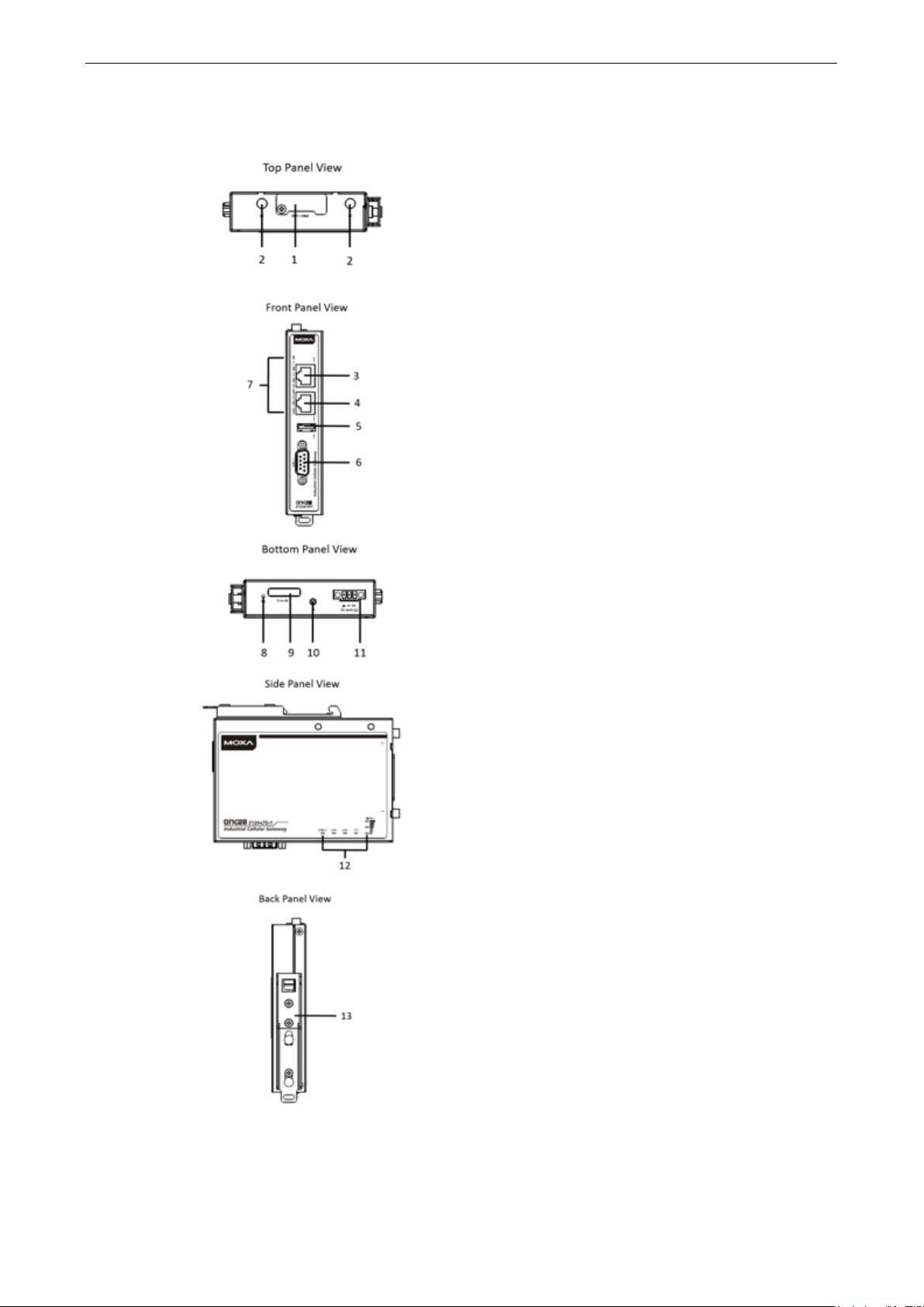
Functional Design
1. SIM card holders (SIM 1/SIM 2)
2. 2x2 MIMO cellular antenna port
3. 10/100 Base T(X) Ethernet port 1 (RJ45)
4. 10/100 Base T(X) Ethernet port 2 (RJ45)
5. USB port
6. DB9 serial port
7. LED display
8. Reset button
9. Console port (reserved for engineering use)
10. Grounding screw (M3)
11. Terminal block (V+, V-, GND)
12. LED display
13. DIN-rail mounting kit
Page 8

OnCell 3120-LTE-1 Introduction
1-4
LED Indicators
The LEDs on the front panel of the OnCell 3120-LTE-1 provide a quick and easy means of determining the
current operational status and wireless settings.
The following table summarizes how to read the device’s wireless settings from the LED displays. Additional
information is available in the Chapter 3, Basic Settings section.
Type Color State Meaning
SYS
(2 LEDs)
LAN 1/2
(4 LEDs)
Serial
(2 LEDs)
LTE
(1 LED)
Signal
(3 LEDs)
Green Power on: System startup is complete and the system is in
operation.
Off No power is supplied to the OnCell device.
Green 1.Blinking at 1-sec
intervals
2.Blinking at 2-sec
intervals
3. Blinking at 0.5-
sec intervals
4. Blinking at 5-sec
intervals
Red 1. Steady On
2. Blinking at 1-sec
intervals
Green 10/100 Mbps Ethernet mode.
Off Port is not active.
Green Transmitting or receiving data.
Off Port is not active.
Green LTE is connected.
Green Blinking at 0.5-sec
intervals
Off No cellular connection.
Green
1. The OnCell device has been located by the Wireless
Search Utility.
2. The ABC-02-USB device connected to OnCell device has
been detected.
3. Importing or exporting files from/to the ABC-02-USB
device.
4. The OnCell device is in power saving mode.
1. System error or failure to get an IP address for the
device.
2. Load/save to the ABC-02-USB device failed.
UMTS/HSPA/GSM/GPRS/EDGE is connected.
Signal
Strength*
1-2 0 < SNR ≤
3-4 12 < SNR ≤
5-6 22 < SNR ≤
* Each signal LED is equivalent to a signal strength of 2 levels.
Cellular
RSSI
12
21
31
RSSI Range
(dBm)
113 < RSSI ≤ -89 Marginal-Ok
-89 < RSSI ≤ -73 Ok - Good
-73 < RSSI ≤ -51 Excellent
Comment
Beeper
The beeper emits two short beeps when the system is ready.
Page 9

OnCell 3120-LTE-1 Introduction
1-5
ATTENTION
•
•
Reset Button
The RESET button is located on the bottom panel of the OnCell 3120-LTE-1. You can reboot the OnCell
3120-LTE-1 or reset it to factory default settings by pressing the RESET button with a pointed object such
as an unfolded paper clip.
• System reboot: Hold the RESET button down for under 5 seconds and then release.
• Reset to factory default: Hold the RESET button down for over 5 seconds until the SYS LED turns solid
red. Release the button to reset the OnCell 3120-LTE-1.
The OnCell 3120-LTE-1 is NOT a portable mobile device and should be located at least 20 cm away from
the human body.
The OnCell 3120-LTE-1 is NOT designed for the general public. A well-trained technician should be
enlisted to ensure safe deployment of OnCell 3120-LTE-1 units, and to establish a wireless network.
Page 10

2
2. Getting Started
This chapter explains how to install Moxa’s OnCell 3120-LTE-1 for the first time, and quickly set up your
wireless network and test whether the connection is running well. The Configuration Menu Overview in
Chapter 3 provides a convenient means of determining which functions you need to use.
The following topics are covered in this chapter:
First—time Installation and Configuration
Step 1: Install a SIM Card
Step 2: Turn On the OnCell 3120-LTE-1
Step 3: Connect the OnCell 3120-LTE-1 to a Computer
Step 4: Configure an IP Address for the Computer
Step 5: Access the Web Console
Step 6: Establish a Cellular Connection
Step 7: Verify the Cellular Connection
Page 11
OnCell 3120-LTE-1 Getting Started
2-2
The SIM card slots are inside the
’s
housing. To install a SIM card
the
is
NOTE
In the OnCell
reset the OnCell
192.168.127.25
First—time Installation and Configuration
Before installing the OnCell 3120-LTE-1, make sure that all items in the package checklist are in the box. In
addition, you will need access to a notebook computer or PC equipped with an Ethernet port. The OnCell
3120-LTE-1 has a default IP address that you must use when connecting to the device for the first time.
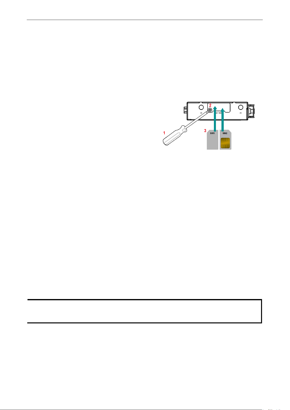
Step 1: Install a SIM Card
Insert one or two 4G SIM cards into the SIM slots located on the bottom of the OnCell 3120-LTE-1.
OnCell 3120-LTE-1
in one of the slots, do
following:
1. Turn off the OnCell 3120-LTE-1.
2. Remove the screw on the SIM card slot cover.
3. Install a SIM card into the SIM card slot.
a. For SIM 1, orient the card such that the gold
contacts are facing down and the cut-off
edge is to the left.
b. For SIM 2, orient the card such that the gold
contacts are facing up and the cut-off edge
to the right.
4. Put back the screw on the SIM card slot cover
and secure the cover by tightening the screw.
Step 2: Turn On the OnCell 3120-LTE-1
Turn on the OnCell 3120-LTE-1 by connecting the power terminal block to a DC power source.
Step 3: Connect the OnCell 3120-LTE-1 to a Computer
Since the OnCell 3120-LTE-1 supports MDI/MDI-X autosensing, you can use either a straight-through cable
or crossover cable to connect the OnCell 3120-LTE-1 to a computer. When a connection is established, the
LED indicator on the OnCell 3120-LTE-1's LAN port lights up.
Step 4: Configure an IP Address for the Computer
You must set an IP address for the computer so that it is on the same subnet as the OnCell 3120-LTE-1.
Since the OnCell 3120-LTE-1’s default IP address is 192.168.127.254 and the subnet mask is
255.255.255.0, you should set the IP address of the computer to 192.168.127.xxx.
3120-LTE-1, you can select Maintenance > Load Factory Default and click Submit to
3120-LTE-1 to the factory default settings, which will reset the IP address to
4.
Page 12
OnCell 3120-LTE-1 Getting Started
2-3
NOTE
Default user name and password:
For security reasons, we strongly recommend changing the default password
To do so, select
the password.
NOTE
After you click
e effective immediately and the
web page will
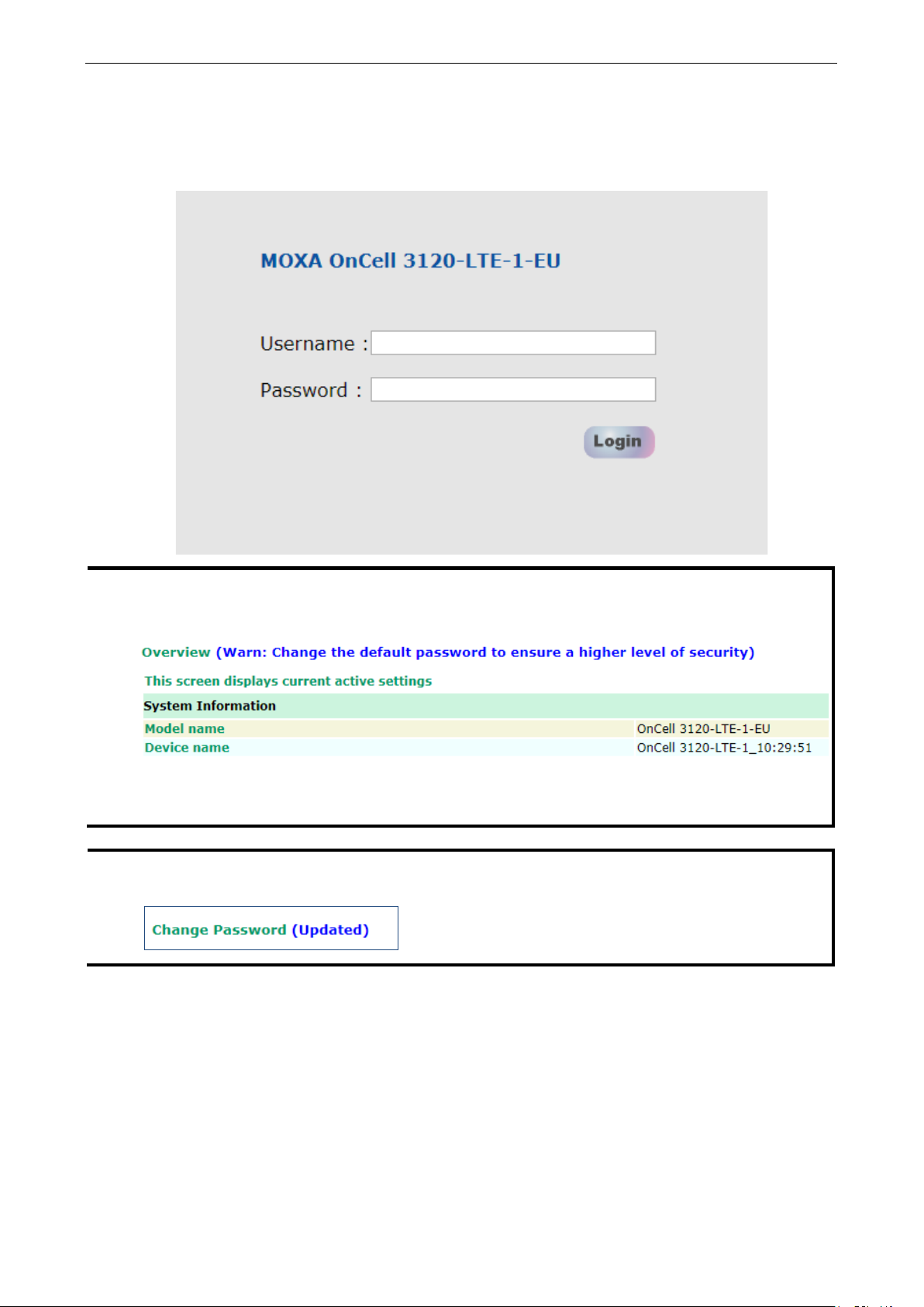
Step 5: Access the Web Console
To access the OnCell 3120-LTE-1 web console:
1. Open a web browser and enter http://192.168.127.254 in the address field.
User Name: admin
Password: moxa
to ensure higher level security.
Maintenance > Change Password, and then follow the on-screen instructions to change
Apply to apply the password change, the new password will b
be refreshed. This is indicated by the text, (Updated) that appears next to the page header:
Page 13

OnCell 3120-LTE-1 Getting Started
2-4
Step 6: Establish a Cellular Connection
After installing the SIM card, obtain the SIM card PIN and APN (Access Point Name) information from your
service provider and configure the cellular WAN settings.
To configure the cellular WAN settings and establish a cellular connection:
1. Log in to the web console.
2. Go to Cellular Settings > Cellular WAN Settings and enter the SIM card PIN and APN values.
3. Restart the OnCell 3120-LTE-1.
The OnCell 3120-LTE-1 automatically establishes a cellular connection to the service provider after it
restarts.
Step 7: Verify the Cellular Connection
You can use one of the following methods to verify the cellular connection:
1. Check the LED display.
Check the LTE LEDs on the front panel.
If the LTE LEDs are steady, it means that the OnCell is connected to the 4G LTE network. If the LTE LEDs
are blinking, it means the OnCell is only connected to the 3G network.
If the LTE LEDs are not lit, it means that a SIM card is not installed or not detected, or the SIM card has
not established a 3G/4G data communication link.
Check the LTE signal strength LEDs to see the current signal strength level. If the LTE signal strength
LEDs are not lit, this indicates that the OnCell has not established a data service. Make sure that you
enter the correct APN information in the web console.
2. Check the Overview page in the web console.
Log in to the web console to display the Overview page. Check the Cellular RSSI, Cellular WAN IP
address, and Cellular Mode fields to identify any connection problems.
For Cellular RSSI (Received Signal Strength Indication), make sure that the value is above 12 in order to
maintain a stable connection.
If the Cellular WAN IP address is not available but the Cellular RSSI is more than 12, make sure that the
APN configuration is correct. The service provider might assign a private WAN IP address, which is not
accessible externally.
3. Test the cellular network access on your computer.
Users with public SIM cards (instead of SIM cards with MDVPN service enabled) can test the connection
to the Internet on your computer (assuming that your computer is connected to an Ethernet port on the
OnCell 3120-LTE-1).
An example of the configuration settings on the computer is given below:
• Laptop IP Address: 192.168.127.10 (on the same subnet as the OnCell gateway)
• Laptop Subnet Mask: 255.255.255.0 (on the same subnet as the OnCell gateway)
• Laptop Default Gateway: 192.168.127.254 (the OnCell gateway IP address)
• Laptop Primary DNS Server: 8.8.8.8 (test with Google's public DNS server)
• Laptop Primary DNS Server: 8.8.4.4 (test with Google's public DNS server)
After the configuration process is complete, your computer will be able to access the Internet.
For information on testing the connection with a DHCP server, refer to Chapter 3, Advanced Settings, DHCP
Server.
Page 14

3
3. Web Console Configuration
This chapter describes the web console that you can use to configure your OnCell 3120-LTE-1 and set up a
wireless network. The following topics are covered in this chapter:
Accessing the Web Console
Configuration Menu Overview
Overview
General Setup
System Information Settings
Interface On/Off
Network Settings
System Time
Operation Mode
Device Control Applications
Socket Applications
Cellular Settings
Cellular WAN Settings
GuaranLink
Auto IP Report Settings
OnCell Central Manager Settings
Advanced Settings
DHCP Server
DDNS
Packet Filters
Port Forwarding Function
SNMP Agent
VPN
IPsec
OpenVPN
Scheduling and Power Management
Serial Port Settings
Logs and Notification
System Log
Syslog
Email Notifications
Trap
SMS
Status
Serial
VPN
DNS Status
SIM Status
DHCP Client List
System Log
LAN Status
System Status
Network Status
Maintenance
Console Settings
Ping Command
Firmware Upgrade
Configuration Import & Export
Load Factory Default
Account Settings
Change Password
Locate Device
Miscellaneous Settings
Troubleshooting
Manual SMS
Remote SMS Control
Saving the Configuration
Restart
Logout
Page 15

OnCell 3120-LTE-1 Web Console Configuration
3-2
NOTE
To use the OnCell
same LAN as the OnCell
are
on the same logical subnet.
The default IP address of an OnCell
NOTE
info
XX, where XX is the country code. The country code indicates the OnCell
bandwidth that it uses. The figures shown in this document
that is displayed for your OnCell
Accessing the Web Console
Moxa OnCell 3120-LTE-1’s web interface provides a convenient way to modify the configuration settings and
access the built-in monitoring and network administration functions. The recommended web browser is
®
Microsoft
Internet Explorer 7.0 and above with JVM (Java Virtual Machine) installed.
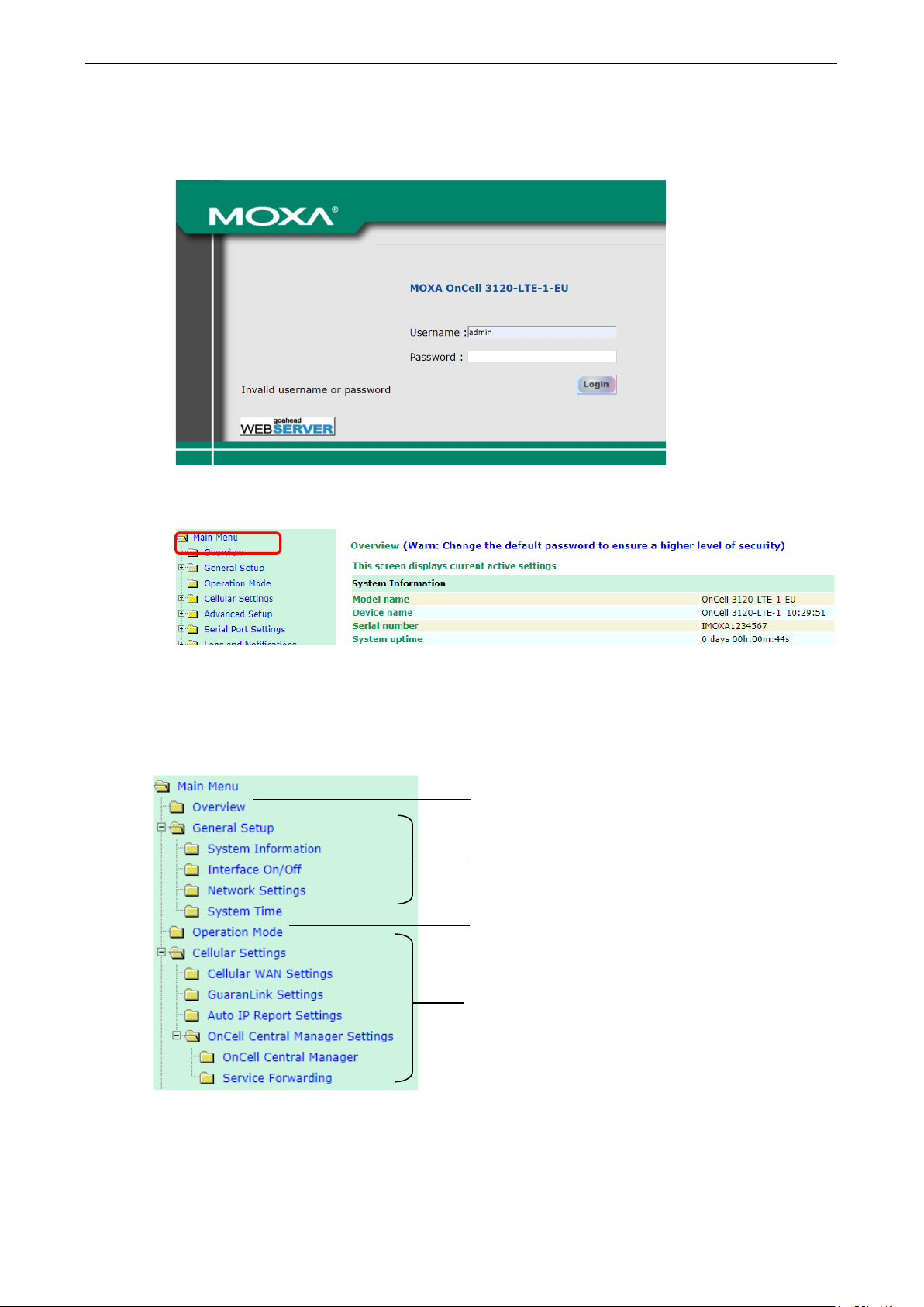
To access the OnCell 3120-LTE-1’s web-based console management interface, do the following
1. Open your web browser and type the OnCell 3120-LTE-1’s IP address in the address field; then, press
Enter.
2. In the login page, enter the Username and Password (the default username is “admin” and password
is “moxa”) and click Login.
It may take a few seconds for the web page to load on your computer.
3120-LTE-1’s management and monitoring functions from a PC host connected to the
3120-LTE-1, you must make sure that the PC host and the OnCell 3120-LTE-1
3120-LTE-1 is 192.168.127.254.
The model name of your OnCell 3120-LTE-1 is shown on the title bar of the web page. You can use this
rmation to identify multiple OnCell 3120-LTE-1 units. The model name is shown as OnCell 3120-LTE-1-
3120-LTE-1 version and the
use an OnCell 3120-LTE-1-EU. The model name
3120-LTE-1 may be different from the one shown in this manual.
Page 16
OnCell 3120-LTE-1 Web Console Configuration
3-3
If an incorrect username or password is entered, a warning message is displayed. The system will lock
the user account based on the settings configured in Maintenance
retry count is 5 times and the default lockout time is 600 seconds. Once an account is locked, the user
will have to wait out the duration of the lockout period before retrying.
For additional details, see Account Settings under Maintenance.
Account Settings. The default
3. Use the navigation panel on the left to access the configuration pages.
In the following sections we will describe each OnCell 3120-LTE-1 management function in detail, starting
with an overview of the links in the navigation panel.
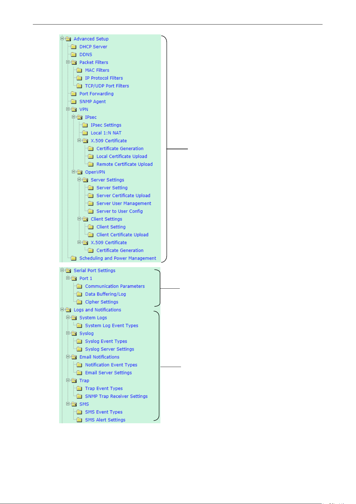
Configuration Menu Overview
Quick overview of the OnCell device status
Basic settings for administering the OnCell and interface
management
Serial port’s operation mode and connection settings
Essential settings for establishing a cellular network,
using GuaranLink and OnCell Central Manager
Page 17
OnCell 3120-LTE-1 Web Console Configuration
3-4
Advanced features to support additional network
management functions and secure wired and wireless
communication.
Note: These advanced functions are optional.
Additional features to support serial operation mode such
as Real COM, Reverse Real COM, and RFC2217.
Application-oriented device management functions to set
up events, traps, and responses via email and SNMP
notification.
Note: These functions are all optional.
Page 18
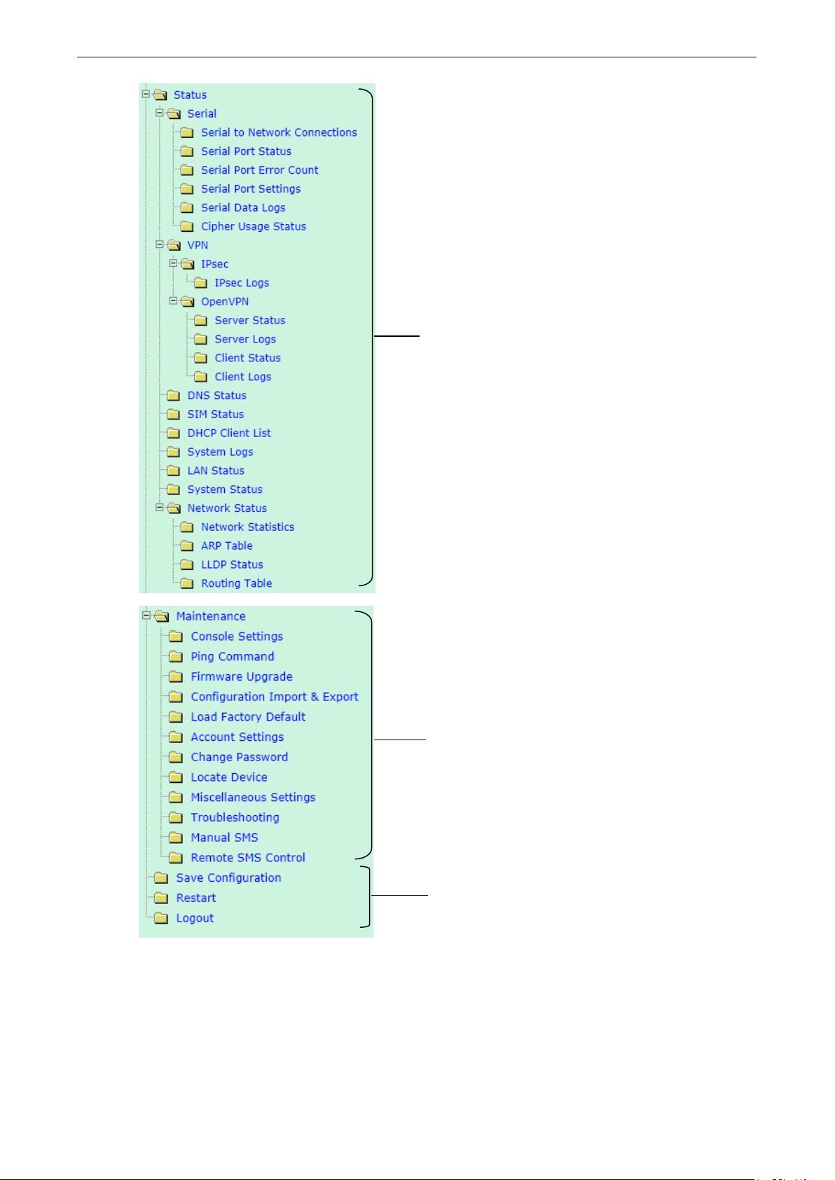
OnCell 3120-LTE-1 Web Console Configuration
3-5
diagnosing network issues
Current status information for monitoring wired/wireless
network performance, advanced services, and device
management functions
Functions for maintaining the OnCell 3120-LTE-1 and for
On-demand functions to support web console
management
Page 19
OnCell 3120-LTE-1 Web Console Configuration
3-6
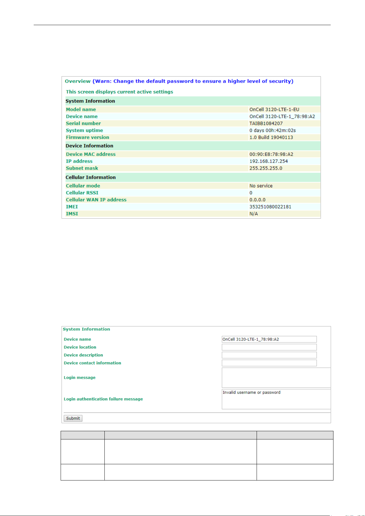
Overview
The Overview page provides a summary of the OnCell 3120-LTE-1’s current status. The information is
categorized into System Information, Device Information, and Cellular Information.
General Setup
The General Setup group includes the most commonly used settings required by administrators to maintain
and control the OnCell 3120-LTE-1.
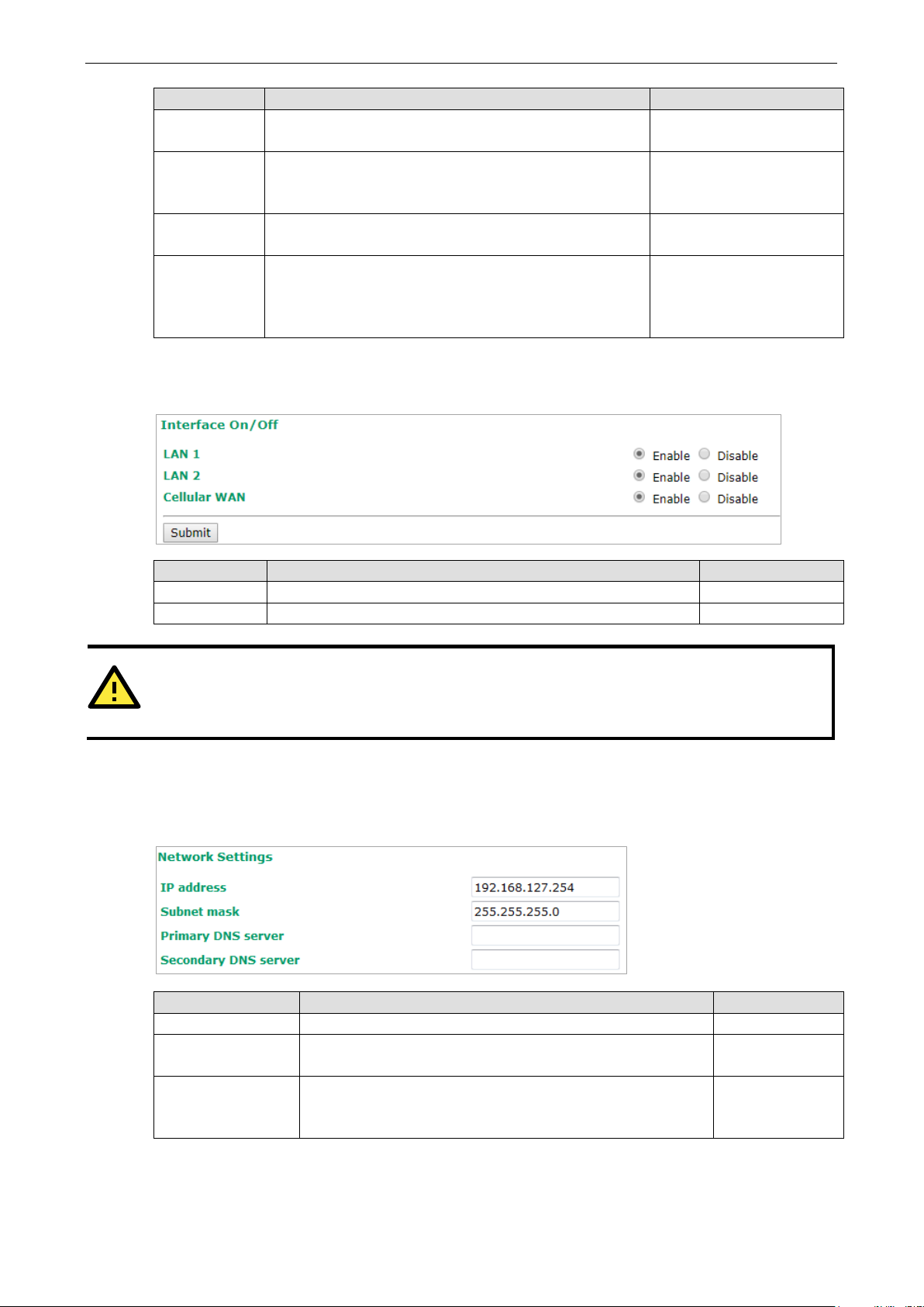
System Information Settings
The System Info items, especially Device name and Device description, are displayed and included on
the Overview page, in SNMP information, and in alarm emails. Setting System Info items makes it easier
to identify the different OnCell 3120-LTE-1 units connected to your network.
Field Description Default setting
Device name Enter a descriptive name (up to 31 characters).
You can also include information that specifies the role or
application of the OnCell 3120-LTE-1 unit.
Device
location
Specify the location (up to 31 characters) of the OnCell
3120-LTE-1
OnCell 3120-LTE-1_[serial
no]
N/A (Not applicable)
Page 20
OnCell 3120-LTE-1 Web Console Configuration
3-7
authentication
ATTENTION
Disabling the cellular WAN interface will disconnect access to remote cellular devices connected through
the cellular WAN.
Primary/Secondary
Field Description Default setting
Device
description
Device
contact
information
Login
Message
Login
failure
message
Enter a description (up to 31 characters) for the OnCell
3120-LTE-1
Enter the contact information (up to 31 characters) of the
person responsible for maintaining this OnCell 3120-LTE-1
Enter the message (up to 31 characters) to display to the
user who logs in into this OnCell 3120-LTE-1.
Enter the message (up to 31 characters) that is displayed
to the user when the login authentication fails.
N/A
N/A
Blank
Invalid username or
password
Interface On/Off
Field Description Default setting
LAN Provides the capability to enable/disable the LAN interface Enable
Cellular WAN Provides the capability to enable/disable the cellular WAN interface. Enable
Network Settings
You can use the Network Settings page to configure TCP/IP settings for the OnCell 3120-LTE-1.
Field Description Default setting
IP address Enter the unique IP address of the OnCell 3120-LTE-1. 192.168.127.254
Subnet mask Enter the subnet mask to specify the type of network to which
the OnCell 3120-LTE-1 is connected.
Enter the IP address of the primary or secondary DNS server.
DNS server
After you specify a DNS server for a website, you can access the
website by entering its URL instead of the IP address.
255.255.255.0
N/A
Page 21
OnCell 3120-LTE-1 Web Console Configuration
3-8
NOTE
The OnCell
the
especially when the network does not have an Internet connection for
is no NTP server on the LAN.
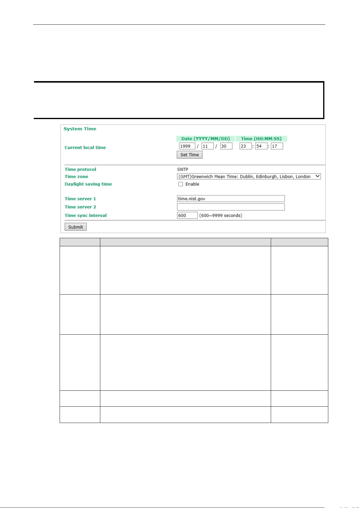
System Time
You can synchronize the system time on the OnCell 3120-LTE-1 based on an NTP (Network Time Protocol)
server or user-specified date and time information. The OnCell 3120-LTE-1 includes the system time in
system logs.
Current local time for the OnCell 3120-LTE-1 after the initial setup or a long-term shutdown,
Field Description Default setting
Current local
time
Time zone Select a time zone from the drop-down list.
Daylight
saving time
Time server
1/2
Time sync
interval
3120-LTE-1 includes a built-in real time clock (RTC). We strongly recommend that you update
accessing the NTP server or if there
The fields indicate the current system time on the OnCell 3120-LTE-
1.
Enter the date and time in the format yyyy/mm/dd hh:mm:ss
To make the changes take effect, click Set Time. An “Updated” text
appears to indicate that the change is complete.
Note: Set the time zone before you configure the current local time.
The default option is GMT (Greenwich Mean Time).
Note: Changing the time zone automatically changes the Current
local time. We strongly recommend that you set the time zone
before you set the Current local time.
Select Enable to activate daylight saving time (DST) or summer
time.
When Daylight saving time is enabled, the following fields appear:
• Starts at: The date that daylight saving time begins.
• Stops at: The date that daylight saving time ends.
• Time offset: Indicates how many hours forward the clock
should be advanced.
Enter the IP address or the domain name of the primary or
secondary NTP server.
Specify how many seconds (600 to 9999) the OnCell 3120-LTE-1
must wait before requesting updates from the NTP server.
N/A
N/A
N/A
time.nist.gov
600
Page 22
OnCell 3120-LTE-1 Web Console Configuration
3-9
Operation Mode
In this section, we describe the various operation modes of the OnCell 3120-LTE-1. The OnCell 3120-LTE-1
modes are grouped by type of application, such as Device Control. The options include an operation mode
that relies on a driver installed on the host computer, and operation modes that rely on TCP/IP socket
programming concepts.
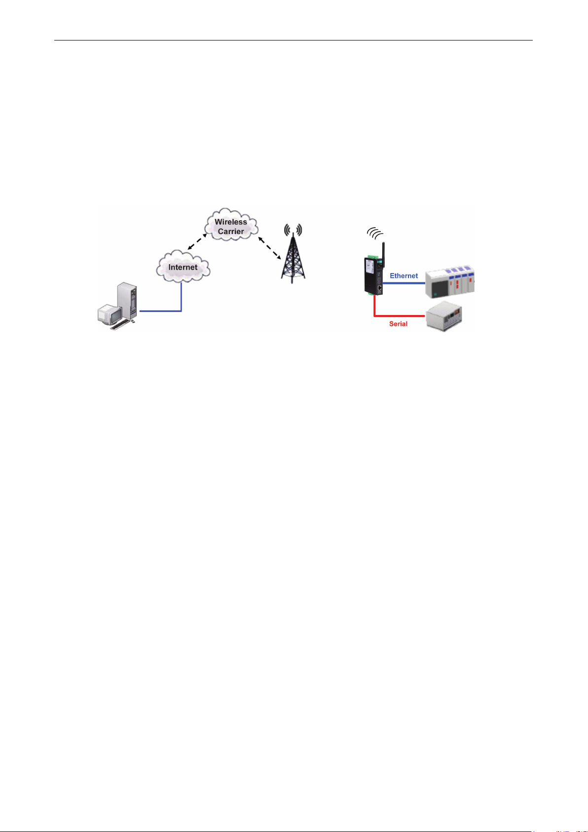
The OnCell 3120-LTE-1 can enable cellular network-in a serial device. OnCell 3120-LTE-1 device is assigned
an IP address by the Internet service provider (ISP). In addition, the OnCell 3120-LTE-1 can enable cellular
connectivity in Ethernet devices on the local Ethernet. See the OnCell Central Manager user’s manual for
details.
The OnCell 3120-LTE-1 enables traditional serial (RS-232/422/485) devices for transmitting data over the
cellular network. The IP gateway can bi-directionally translate data between the serial and IP formats. With
the OnCell 3120-LTE-1, your computer will be able to access, manage, and configure remote facilities and
equipment over the cellular network from anywhere in the world.
Traditional SCADA and data collection systems rely on serial ports to collect data from various kinds of
instruments. Since the OnCell 3120-LTE-1 network-enables instruments equipped with an RS-232, RS-422,
or RS-485 communication port, your SCADA and data collection systems will be able to access all
instruments connected to a standard TCP/IP network, regardless of whether the devices are used locally or
at a remote site.
The OnCell 3120-LTE-1 is an external IP-based network device that allows you to expand a serial port for a
host computer on demand. As long as your host computer supports the TCP/IP protocol, you will not be
limited by the host computer’s bus limitation (such as ISA or PCI), nor will you be limited if you do not have
drivers for various operating systems.
In addition to providing socket access, the OnCell 3120-LTE-1 also comes with a Real COM driver and a
Reverse Real COM driver that transmits all serial signals intact. This enables you to preserve your existing
COM-based software without needing to invest in additional software.
Three different socket modes are available: TCP Server, TCP Client, and UDP. The main difference between
the TCP and UDP protocols is that TCP guarantees delivery of data by requiring the recipient to send an
acknowledgement to the sender. UDP does not require this type of verification, making it possible to offer
faster delivery. UDP also allows you to unicast data to one IP, or multicast the data to a group of IP
addresses.
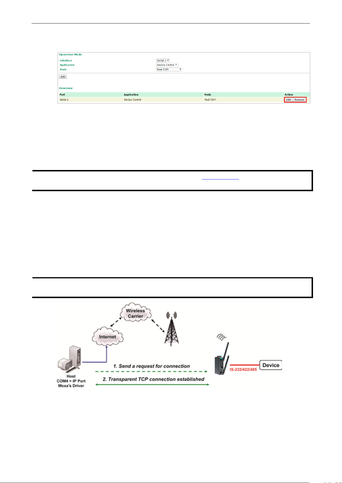
The serial port of the OnCell 3120-LTE-1 can be configured to different operation modes for different
applications. After selecting the application and mode, click Add and the selected mode will be shown in the
“Overview” below.
Page 23
OnCell 3120-LTE-1 Web Console Configuration
3-10
NOTE
You can download the Moxa Drivers for operation modes from
File Name: Windows Driver Manager
NOTE
In order to avoid a TCP port conflict with other applications, please aware of that data port used on the
driver is 950 a
You can click on Edit to continue with the detailed configuration of the selected operation mode, or click on
Remove to disable the serial port.
Device Control Applications
The OnCell 3120-LTE-1 offers the following modes for device control applications: Real COM, Reverse Real
COM, and RFC2217 modes.
Real COM Mode
In Real COM mode, the bundled drivers are able to establish a transparent connection between a host and a
serial device by mapping the serial port on the OnCell 3120-LTE-1 to a local COM port on the host
computer. Real COM mode supports up to 2 simultaneous connections that enable 2 hosts to simultaneously
collect data from the same serial device.
One of the major conveniences of using Real COM mode is that it allows you to use software that was
written for pure serial communication applications. The OnCell COM driver intercepts data sent to the host’s
COM port, packs it into a TCP/IP packet, and then redirects it through the host’s Ethernet card to the
Internet. At the other end of the connection, the OnCell 3120-LTE-1 accepts the IP frame from the cellular
network, unpacks the TCP/IP packet, and then transparently sends the data through the serial port to the
attached serial device.
nd the command port is 966.
www.moxa.com.
Page 24
OnCell 3120-LTE-1 Web Console Configuration
3-11
ATTENTION
When Max connection is greater than 1, the
2 hosts are allowed access to the port at the same time). When using a multi
OnCell 3120
web console, and all
hosts connected to the port must use identical serial settings. If one of the hosts opens the COM port with
different serial settings, data will not be transmitted properly.
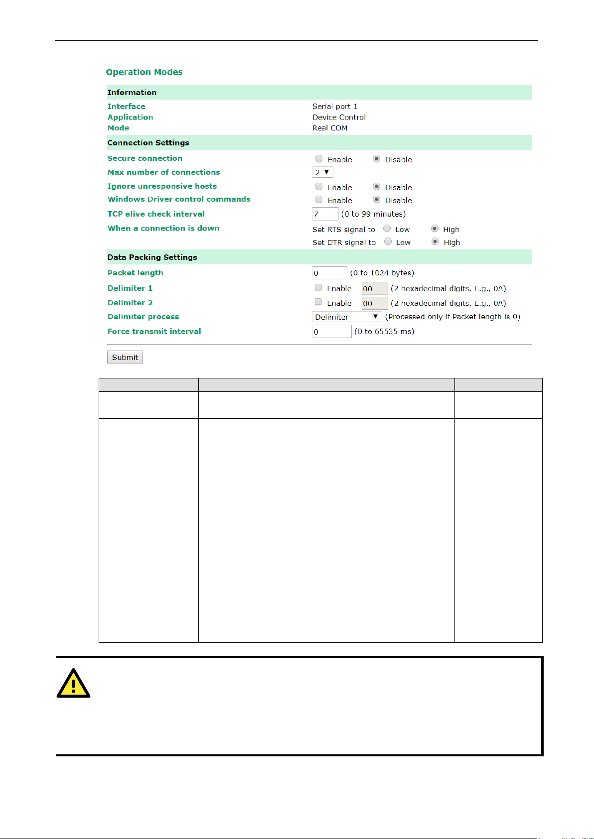
Setting Description Factory Default
Secure connection If you select Enable, data sent through the Ethernet will be
encrypted with SSL.
Max number of
connections
This field is used if you need to receive data from different
hosts simultaneously. When set to 1, only one specific host
can access this port of the OnCell 3120-LTE-1, and the OnCell
COM driver on that host will have full control over the port.
When set to 2, the specified number of hosts’ OnCell COM
driver may open this port at the same time. When multiple
hosts on the OnCell COM driver open the port at the same
time, the COM driver only provides a pure data tunnel --no
control ability unless “Allow Driver Control” is enabled. The
serial port parameters will use firmware settings instead of
depending on your application program (AP).
Application software that is based on the COM driver will
receive a driver response of “success” when the software
uses any of the Win32 API functions. The firmware will only
send data back to the driver on the host.
Data will be sent first-in-first-out when data comes into the
OnCell 3120-LTE-1 from the Cellular or Ethernet interface.
Disable
1
-LTE-1 will use the serial communication parameters as defined here in the
OnCell 3120-LTE-1 will use a multi-connection application (i.e.,
-connection application, the
Page 25

OnCell 3120-LTE-1 Web Console Configuration
3-12
1 will listen for another TCP connection from
connection gets disconnected. Use “always high” if you do not
specified, data in the buffer will be sent as soon it reaches the
characters act as the delimiter to control when data should be
Setting Description Factory Default
Ignore unresponsive
hosts
Windows Driver
control commands
TCP alive check
interval
When a connection
is down
This option determines how the port will proceed if multiple
hosts are connected and one or more host(s) stops
responding when the port is transmitting data. If you select
Disable, the port will wait until the data has been
transmitted successfully to all hosts before transmitting the
next group of data. If you select Enable, the port will ignore
the host that stopped responding and continue data
transmission to the other hosts.
This option determines how the port will proceed if driver
control commands are received from multiple hosts that are
connected to the port. If Disable is selected, driver control
commands will be ignored. If Enable is selected, control
commands will be accepted, with the most recent command
received taking precedence.
This field specifies how long the OnCell 3120-LTE-1 will wait
for a response to “keep alive” packets before closing the TCP
connection. The OnCell 3120-LTE-1 checks the connection
status by sending periodic “keep alive” packets. If the remote
host does not respond to the packet within the time specified
in this field, the OnCell 3120-LTE-1 will force the existing TCP
connection to close. For socket and device control modes, the
OnCell 3120-LTE-
another host after closing the connection. If TCP alive check
time is set to 0, the TCP connection will remain open and will
not send any “keep alive” packets.
You can configure what happens to the RTS and DTR signals
when the Cellular or Ethernet connection goes down. For
some applications, serial devices need to know the Cellular or
Ethernet link status through RTS or DTR signals sent through
the serial port. Use “low” if you want the RTS and DTR signal
to change their state to low when the Cellular or Ethernet
Disable
Disable
7 min
Always High
want the cellular or Ethernet connection status to affect the
RTS or DTR signals.
Packing length The Packing length setting refers to the maximum amount
of data that is allowed to accumulate in the serial port buffer
before sending. At the default of 0 for packet length, no
maximum amount is specified and data in the buffer will be
sent as specified by the delimiter settings or when the buffer
is full. When a packet length between 1 and 1024 bytes is
specified length.
Delimiter 1
Delimiter 2
When Delimiter 1 is enabled, the serial port will queue the
data in the buffer and send the data to the Cellular or
Ethernet port when a specific character, entered in hex
format, is received. A second delimiter character may be
enabled and specified in the Delimiter 2 field, so that both
sent.
0
00
Page 26

OnCell 3120-LTE-1 Web Console Configuration
3-13
ATTENTION
In order to enable a delimiter, packet length must be set to 0.
conjunction with
delimiter is enabled, the OnCell 3120
exceeds 1 KB.
Setting Description Factory Default
Delimiter process The Delimiter process field determines how the data is
Force transmit This parameter defines how large a gap in serial
Delimiter 1 and never on its own; otherwise there may be data errors. Even when a
-LTE-1 will still pack and send the data when the amount of data
handled when a delimiter is received. Delimiter 1 must be
enabled for this field to have effect. If Delimiters 1 and 2 are
both enabled, both characters must be received for the
delimiter process to take place.
• Delimiter: Data in the buffer will be transmitted when the
delimiter is received.
• Delimiter + 1: Data in the buffer will be transmitted after
1 additional byte is received following the delimiter.
• Delimiter + 2: Data in the buffer will be transmitted after
2 additional bytes are received following the delimiter.
• Strip Delimiter: Data in the buffer is first stripped of the
delimiter before being transmitted.
communication the OnCell 3120-LTE-1 will allow before
packing the serial data in its internal buffer for network
transmission.
As data is received through the serial port, it is stored by the
OnCell 3120-LTE-1 in the internal buffer. The OnCell 3120-
LTE-1 transmits the data stored in the buffer via TCP/IP when
the internal buffer is full or as specified by the force-transmit
time.
When this field is set to 0, the force transmit time is disabled
and transmission is determined solely by the data in the
internal buffer. When the force transmit time is set to a value
from 1 to 65535, the TCP/IP protocol software will pack the
serial data received for transmission after the gap in serial
communication exceeds the specified force transmit time.
The optimal force-transmit time setting depends on your
application. However, it must be set to a value that is more
than one-character interval within the specified baudrate. For
example, assume that the serial port is set to 1200 bps, 8
data bits, 1 stop bit, and no parity. In this case, the total
number of bits needed to send a character is 10 bits, and the
time required to transfer one character is (10 (bits) / 1200
(bits/s)) × 1000 (ms/s) = 8.3 ms. Therefore, you should
set the force transmit time to be greater than 8.3 ms, so in
this case, it must be greater than or equal to 10 ms.
If it is necessary to send a series of characters in the same
packet, the serial device will need to send that series of
characters within the specified force transmit time, and the
total length of data must be less than or equal to the OnCell
3120-LTE-1’s internal buffer size (1 KB per port).
Delimiter 2 should only be enabled in
Delimiter
0 ms
Page 27
OnCell 3120-LTE-1 Web Console Configuration
3-14
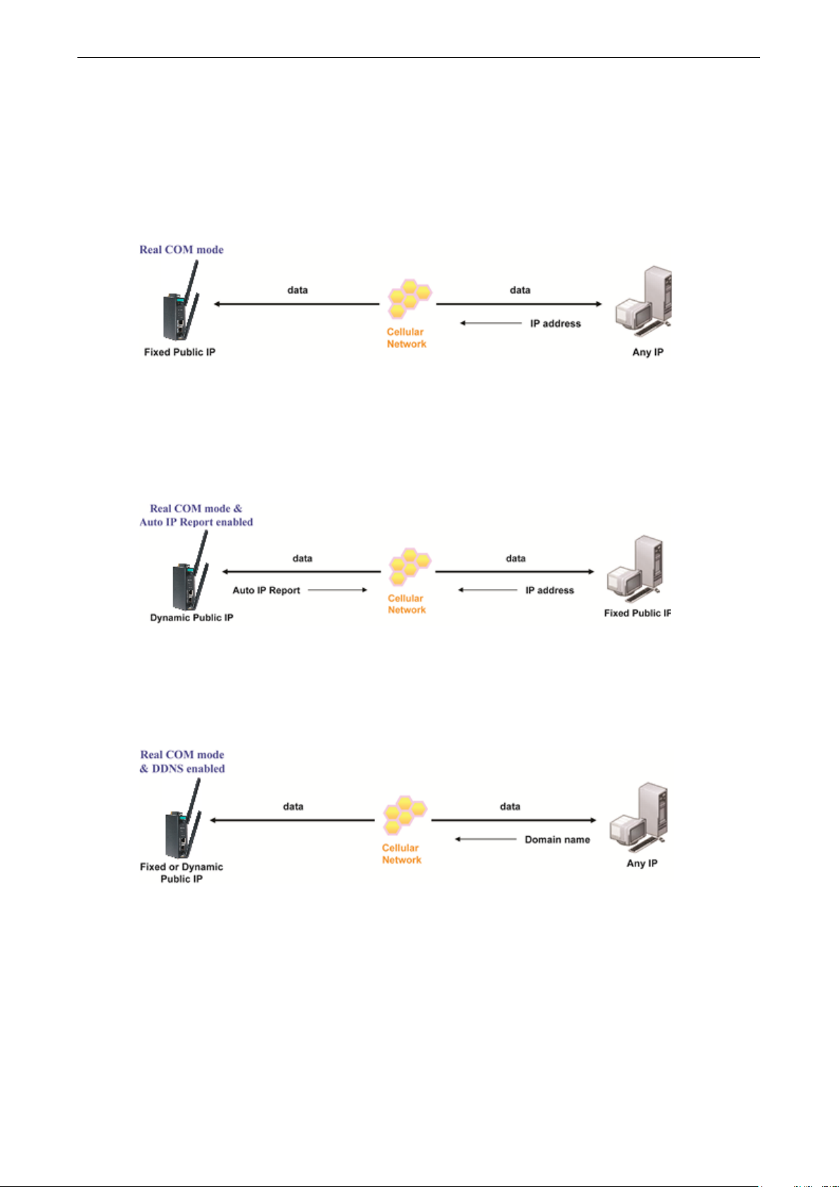
Types of Real COM Connection
This section illustrates the types of Real COM connections you can use, depending on the service you obtain
from your local cellular service provider.
Fixed Public IP for OnCell
If your cellular service provider offers a fixed public IP address after you connect to the cellular network,
you can access the OnCell 3120-LTE-1 via a host PC using either a private IP or public IP.
Utilize Auto IP report
If your cellular service provider offers a dynamic public IP address after you connect to the cellular network,
you can access the OnCell 3120-LTE-1 via a host PC using a fixed public IP. Since the IP address of the
OnCell 3120-LTE-1 is changed each time it is connected to the cellular network, the host IP can be notified
of the change by an Auto IP Report message sent from the OnCell 3120-LTE-1. Please refer to Auto IP
Report Settings to see the format of the Auto IP Report Protocol.
Domain name with DDNS
If your cellular service provider offers a public IP address after you connect to the cellular network, you can
also access the OnCell 3120-LTE-1 using the domain name. To do this, you will need to register with a
DDNS service provider and then enable the DDNS function in the OnCell 3120-LTE-1. Please refer to
Appendix B for more information.
Page 28
OnCell 3120-LTE-1 Web Console Configuration
3-15
1 will listen for another TCP connection from
specified, data in the buffer will be sent as soon it reaches the
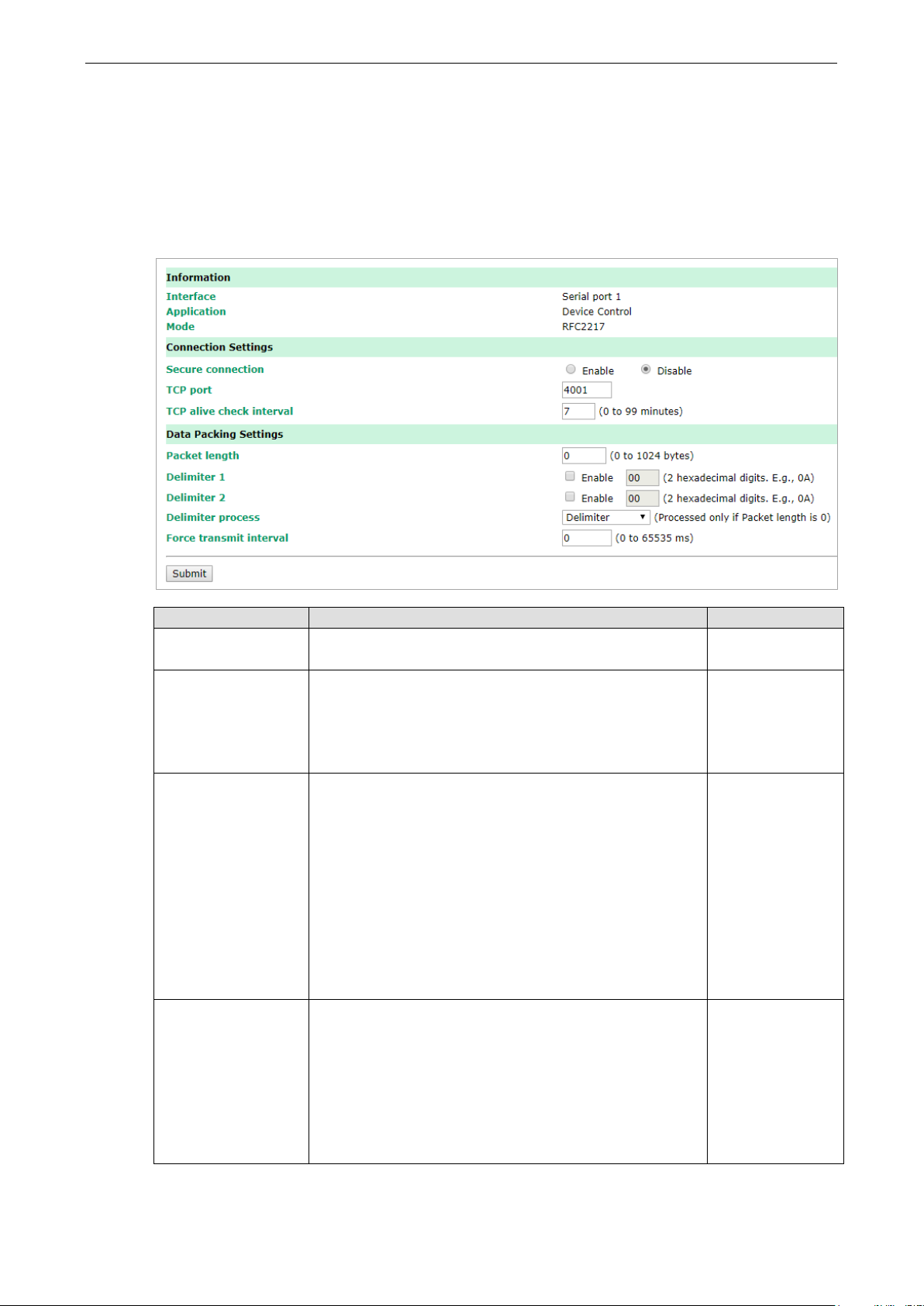
RFC 2217 Mode
RFC-2217 mode is similar to Real COM mode in that a driver is used to establish a transparent connection
between a host computer and a serial device by mapping the serial port on the OnCell 3120-LTE-1 to a local
COM port on the host computer. RFC2217 defines general COM port control options based on the Telnet
protocol. Third party drivers supporting RFC-2217 are widely available on the Internet and can be used to
implement virtual COM mapping to your OnCell 3120-LTE-1’s serial port.
Setting Description Factory Default
Secure connection If you select Enable, data sent through the Ethernet will be
encrypted with SSL.
TCP port This is the TCP port number assignment for the serial port on
the OnCell 3120-LTE-1. It is the port number that the serial
port uses to listen to connections, and that other devices
must use to contact the serial port. To avoid conflicts with
well-known TCP ports, the default is set to 4001.
TCP alive check
interval
Packing length The Packing length setting refers to the maximum amount
This field specifies how long the OnCell 3120-LTE-1 will wait
for a response to “keep alive” packets before closing the TCP
connection. The OnCell 3120-LTE-1 checks connection status
by sending periodic “keep alive” packets. If the remote host
does not respond to the packet within the time specified in
this field, the OnCell 3120-LTE-1 will force the existing TCP
connection to close. For socket and device control modes, the
OnCell 3120-LTE-
another host after closing the connection. If TCP alive check
time is set to 0, the TCP connection will remain open and will
not send any “keep alive” packets.
of data that is allowed to accumulate in the serial port buffer
before sending. At the default of 0 for packet length, no
maximum amount is specified and data in the buffer will be
sent as specified by the delimiter settings or when the buffer
is full. When a packet length between 1 and 1024 bytes is
Disable
4001
7 min
0
specified length.
Page 29

OnCell 3120-LTE-1 Web Console Configuration
3-16
characters act as the delimiter to control when data should be
ATTENTION
In order to enable a delimiter, the packet length must be set to 0.
conjunction with
the OnCell 3120
Setting Description Factory Default
Delimiter 1
Delimiter 2
When Delimiter 1 is enabled, the serial port will queue the
data in the buffer and send the data to the Cellular or
Ethernet port when a specific character, entered in hex
format, is received. A second delimiter character may be
enabled and specified in the Delimiter 2 field, so that both
sent.
Disabled
Setting Description Factory Default
Delimiter process The Delimiter process field determines how the data is
Force transmit This parameter defines how large a gap in serial
Delimiter 1 and never on its own to avoid data errors. Even when a delimiter is enabled,
-LTE-1 will still pack and send the data when the amount of data exceeds 1 KB.
handled when a delimiter is received. Delimiter 1 must be
enabled for this field to have effect. If Delimiters 1 and 2 are
both enabled, both characters must be received for the
delimiter process to take place.
• Delimiter: Data in the buffer will be transmitted when the
delimiter is received.
• Delimiter + 1: Data in the buffer will be transmitted after
1 additional byte is received following the delimiter.
• Delimiter + 2: Data in the buffer will be transmitted after
2 additional bytes are received following the delimiter.
• Strip Delimiter: Data in the buffer is first stripped of the
delimiter before being transmitted.
communication the OnCell 3120-LTE-1 will allow before
packing the serial data in its internal buffer for network
transmission.
As data is received through the serial port, it is stored by the
OnCell 3120-LTE-1 in the internal buffer. The OnCell 3120-
LTE-1 transmits the data stored in the buffer via TCP/IP when
the internal buffer is full or as specified by the force-transmit
time.
When this field is set to 0, the force transmit time is disabled
and transmission is determined solely by the data in the
internal buffer. When the force transmit time is set to a value
from 1 to 65535, the TCP/IP protocol software will pack the
serial data received for transmission after the gap in serial
communication exceeds the specified force transmit time.
The optimal force-transmit time setting depends on your
application. However, it must be set to a value that is more
than one-character interval within the specified baudrate. For
example, assume that the serial port is set to 1200 bps, 8
data bits, 1 stop bit, and no parity. In this case, the total
number of bits needed to send a character is 10 bits, and the
time required to transfer one character is (10 (bits) / 1200
(bits/s)) × 1000 (ms/s) = 8.3 ms. Therefore, you should
Delimiter 2 should only be enabled in
Delimiter
0 ms
Page 30
OnCell 3120-LTE-1 Web Console Configuration
3-17
NOTE
You can download the Moxa Drivers for operation modes from
File Name: Windows Driver Manager
Setting Description Factory Default
set the force transmit time to be greater than 8.3 ms, so in
this case, it must be greater than or equal to 10 ms.
If it is necessary to send a series of characters in the same
packet, the serial device will need to send that series of
characters within the specified force transmit time, and the
total length of data must be less than or equal to the OnCell
3120-LTE-1’s internal buffer size (1 KB per port).
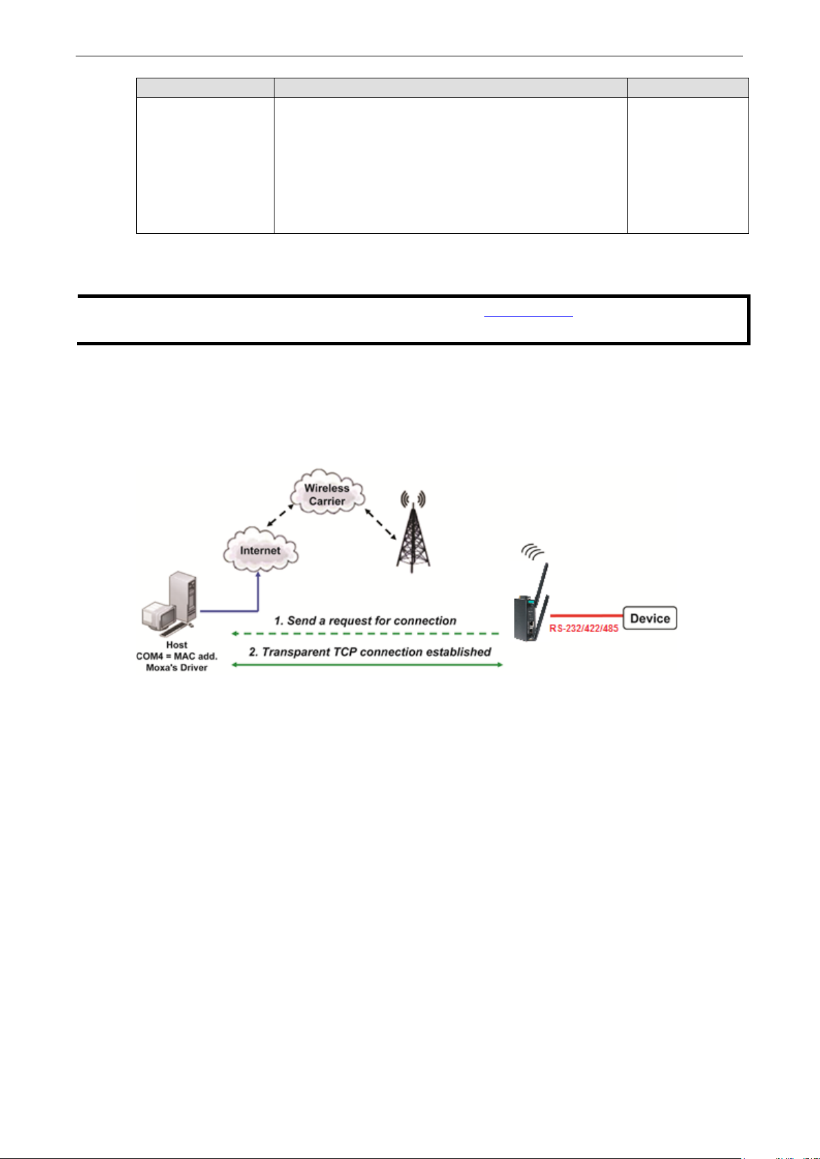
Reverse Real COM Mode
Reverse Real COM mode uses a mechanism similar to port mapping to enable your remote device that is
using a private IP address to remain accessible to external hosts. When this mode is enabled, the Moxa
driver that comes with the device establishes a transparent connection from the device to the remote host
by mapping the device’s serial port to a local COM port on the remote host. Reverse Real COM mode
supports up to 2 simultaneous connections that enable serial devices to send data to 2 hosts
simultaneously.
www.moxa.com.
Page 31

OnCell 3120-LTE-1 Web Console Configuration
3-18
ATTENTION
Up to 2 connections can be established b
Port 60950 might be blocked by a firewall. You should make sure the port is NOT blocked before you start
using it.
ATTENTION
The destination IP address parameter can be the IP address
Setting Description Factory Default
Secure connection If you select Enable, data sent through the Ethernet will be
encrypted with SSL.
Destination address
1 through 2
Destination data
port
Destination cmd
port
Specifying an IP address allows the OnCell 3120-LTE-1 to
connect actively to the remote host. At least one destination
must be provided.
This is the TCP port number assignment for the remote
host/server. It is the port number that the OnCell 3120-LTE-
1’s serial port uses to establish connections with a remote
host/server. To avoid conflicts with well-known TCP ports, the
default is set to 60950.
The Command port is the COM port for listening to SSDK
commands from the host. In order to prevent a COM port
conflict with other applications, the user can set the
Command port to another port if needed.
etween OnCell 3120-LTE-1 hosts.
Disable
None
60950
60966
Setting Description Factory Default
Designated local
port 1 through 2
Use these fields to specify the designated local ports.
(Example: 7010 through 7320)
or domain name.
0
Page 32

OnCell 3120-LTE-1 Web Console Configuration
3-19
1 will listen for another TCP connection from
connection gets disconnected. Use “always high” if you do not
specified, data in the buffer will be sent as soon it reaches the
Setting Description Factory Default
Ignore unresponsive
hosts
Windows Driver
control commands
TCP alive check
interval
When a connection
is down
This option determines how the port will proceed, if multiple
hosts are connected and one or more of the hosts stop
responding as the port is transmitting data. If you select
Disable, the port will wait until the data has been transmitted
successfully to all hosts before transmitting the next group of
data. If you select Enable, the port will ignore the host that
stopped responding and continue data transmission to the
other hosts.
This option determines how the port will proceed if driver
control commands are received from multiple hosts that are
connected to the port. If Disable is selected, driver control
commands will be ignored. If Enable is selected, control
commands will be accepted, with the most recent command
received taking precedence.
This field specifies how long the OnCell 3120-LTE-1 will wait
for a response to “keep alive” packets before closing the TCP
connection. The OnCell 3120-LTE-1 checks connection status
by sending periodic “keep alive” packets. If the remote host
does not respond to the packet within the time specified in
this field, the OnCell 3120-LTE-1 will force the existing TCP
connection to close. For socket and device control modes, the
OnCell 3120-LTE-
another host after closing the connection. If TCP alive check
time is set to 0, the TCP connection will remain open and will
not send any “keep alive” packets.
You can configure what happens to the RTS and DTR signals
when the Cellular or Ethernet connection goes down. For
some applications, serial devices need to know the Cellular or
Ethernet link status through RTS or DTR signals sent through
the serial port. Use “low” if you want the RTS and DTR signal
to change their state to low when the Cellular or Ethernet
Disable
Disable
7 min
Always high
want the cellular or Ethernet connection status to affect the
RTS or DTR signals.
Packet length The Packet length setting refers to the maximum amount of
data that is allowed to accumulate in the serial port buffer
before sending. At the default of 0 for packet length, no
maximum amount is specified and data in the buffer will be
sent as specified by the delimiter settings or when the buffer
is full. When a packet length between 1 and 1024 bytes is
specified length.
Delimiter 1
Delimiter 2
When Delimiter 1 is enabled, the serial port will queue the
data in the buffer and send the data to the Cellular or
Ethernet port when a specific character, entered in hex
format, is received.
A second delimiter character may be enabled and specified in
the Delimiter 2 field, so that both characters act as the
delimiter to control when data should be sent.
0
Disabled
Page 33

OnCell 3120-LTE-1 Web Console Configuration
3-20
ATTENTION
In order to enable a delimiter, packet length must be set to 0.
conjunction with
the OnCell 3120
Setting Description Factory Default
Delimiter process The Delimiter process field determines how the data is
Force transmit This parameter defines how large a gap in serial
Delimiter 1 and never on its own to avoid data errors. Even when a delimiter is enabled,
-LTE-1 will still pack and send the data when the amount of data exceeds 1 KB.
handled when a delimiter is received. Delimiter 1 must be
enabled for this field to have effect. If Delimiters 1 and 2 are
both enabled, both characters must be received for the
delimiter process to take place.
• Delimiter: Data in the buffer will be transmitted when the
delimiter is received.
• Delimiter + 1: Data in the buffer will be transmitted after 1
additional byte is received following the delimiter.
• Delimiter + 2: Data in the buffer will be transmitted after 2
additional bytes are received following the delimiter.
• Strip Delimiter: Data in the buffer is first stripped of the
delimiter before being transmitted.
communication the OnCell 3120-LTE-1 will allow before
packing the serial data in its internal buffer for network
transmission.
As data is received through the serial port, it is stored by the
OnCell 3120-LTE-1 in the internal buffer. The OnCell 3120-
LTE-1 transmits the data stored in the buffer via TCP/IP when
the internal buffer is full or as specified by the force-transmit
time.
When this field is set to 0, the force transmit time is disabled
and transmission is determined solely by the data in the
internal buffer. When the force transmit time is set to a value
from 1 to 65535, the TCP/IP protocol software will pack the
serial data received for transmission after the gap in serial
communication exceeds the specified force transmit time.
The optimal force-transmit time setting depends on your
application. However, it must be set to a value that is more
than one-character interval within the specified baudrate. For
example, assume that the serial port is set to 1200 bps, 8
data bits, 1 stop bit, and no parity. In this case, the total
number of bits needed to send a character is 10 bits, and the
time required to transfer one character is (10 (bits) / 1200
(bits/s)) × 1000 (ms/s) = 8.3 ms. Therefore, you should
set the force transmit time to be greater than 8.3 ms, so in
this case, it must be greater than or equal to 10 ms.
If it is necessary to send a series of characters in the same
packet, the serial device will need to send that series of
characters within the specified force transmit time, and the
total length of data must be less than or equal to the OnCell
3120-LTE-1’s internal buffer size (1 KB per port).
Delimiter 2 should only be enabled in
Delimiter
0 ms
Page 34

OnCell 3120-LTE-1 Web Console Configuration
3-21
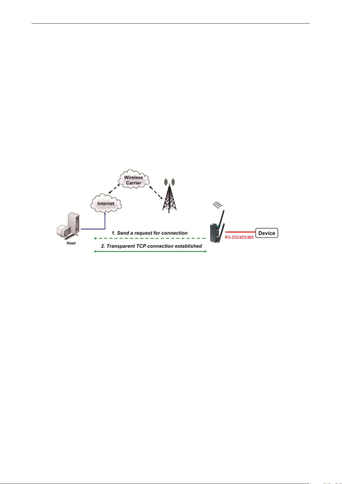
Types of Reverse Real COM Connection
Reverse Real COM to PC’s IP address
Most cellular service providers only provide customers with a dynamic private IP address, which means that
the OnCell 3120-LTE-1 will only obtain an IP address once it is connected to the cellular network. Reverse
Real COM is a great feature that allows a PC host to access an OnCell 3120-LTE-1 configured with private IP
address.
Reverse Real COM to PC’s domain name
With Reverse Real COM mode, you can connect to a PC host using the PC’s IP address. You can also connect
to your PC host with the PC’s domain name, if you have one. Please refer to Appendix B for more
information.
Page 35
OnCell 3120-LTE-1 Web Console Configuration
3-22
Socket Applications
The OnCell 3120-LTE-1 offers the following modes for socket applications: TCP Server, TCP Client, and UDP.
TCP Server Modes
In TCP Server mode, the serial port on the OnCell 3120-LTE-1 is assigned a port number. The host
computer initiates contact with the OnCell 3120-LTE-1, establishes the connection, and receives data from
the serial device. This operation mode also supports up to 2 simultaneous connections, enabling multiple
hosts to collect data from the same serial device at the same time.
As illustrated in the figure, data transmission proceeds as follows: The host requests a connection from the
OnCell 3120-LTE-1, which is configured for TCP Server mode. Once the connection is established, data can
be transmitted in both directions between the host and the OnCell 3120-LTE-1.
TCP Server mode includes optional data encryption using SSL
Page 36

OnCell 3120-LTE-1 Web Console Configuration
3-23
open the TCP connection to the serial port. When set to 2, the
Setting Description Factory Default
Secure connection If you select Enable, data sent through the Ethernet will be
encrypted with SSL.
Data port This is the TCP port number assignment for the serial port on
the OnCell 3120-LTE-1. It is the port number that the serial
port uses to listen to connections, and that other devices
must use to contact the serial port. To avoid conflicts with
well-known TCP ports, the default is set to 4001.
Cmd port The Command port is the TCP port for listening to SSDK
commands from the host. In order to prevent a TCP port
conflict with other applications, the user can set the
Command port to another port if needed.
Max number of
connections
Ignore unresponsive
hosts
This field is used if you need to receive data from different
hosts simultaneously. When set to 1, only a single host may
specified number of hosts may open this port at the same
time.
When multiple hosts establish a TCP connection to the serial
port at the same time, the OnCell 3120-LTE-1 will duplicate
the serial data and transmit it to all the hosts. Cellular or
Ethernet data is sent on a first-in first-out basis to the serial
port when data comes into the OnCell 3120-LTE-1 from the
Cellular or Ethernet interface.
This option determines how the port will proceed if multiple
hosts are connected and one or more of the hosts stop
responding as the port is transmitting data. If you select
Disable, the port will wait until the data has been
transmitted successfully to all hosts before transmitting the
Disable
4001
966
1
Disable
Page 37

OnCell 3120-LTE-1 Web Console Configuration
3-24
ATTENTION
You should make sure the inactivity time value used here is less
GSM/GPRS configuration page. The GSM/GPRS connection must be maintained in order to achieve the
inactivity time behavior of the TCP connection.
ATTENTION
If used, the Inactivity time setting should be greater than the Force
unintended loss of data due to the session being disconnected, it is highly recommended that this value is
set large enough so that the intended data transfer is completed.
specified, data in the buffer will be sent as soon it reaches the
Setting Description Factory Default
next group of data. If you select Enable, the port will ignore
the host that stopped responding and continue data
transmission to the other hosts.
Windows Driver
control commands
TCP alive check
interval
This option determines how the port will proceed if driver
control commands are received from multiple hosts that are
connected to the port. If Disable is selected, driver control
commands will be ignored. If Enable is selected, control
commands will be accepted, with the most recent command
received taking precedence.
This field specifies how long the OnCell 3120-LTE-1 will wait
for a response to “keep alive” packets before closing the TCP
connection. The OnCell 3120-LTE-1 checks connection status
by sending periodic “keep alive” packets. If the remote host
does not respond to the packet within the time specified in
this field, the OnCell 3120-LTE-1 will force the existing TCP
connection to close. For socket and device control modes, the
OnCell 3120-LTE-1 will listen for another TCP connection from
another host after closing the connection. If TCP alive check
time is set to 0, the TCP connection will remain open and will
not send any “keep alive” packets.
Disable
7 min
Setting Description Factory Default
Inactivity time This field specifies how long the OnCell 3120-LTE-1 will wait
for incoming and outgoing data through the serial port before
closing the TCP connection. The TCP connection is closed if
there is no incoming or outgoing data through the serial port
for the specified Inactivity time. If this field is set to 0, the
TCP connection is kept active until a connection close request
is received.
Setting Description Factory Default
Packet length The Packet length setting refers to the maximum amount of
data that is allowed to accumulate in the serial port buffer
before sending. At the default of 0 for packet length, no
maximum amount is specified and data in the buffer will be
sent as specified by the delimiter settings or when the buffer
is full. When a packet length between 1 and 1024 bytes is
than the inactivity time value on the
0 ms
transmit time. To prevent the
0
specified length.
Page 38

OnCell 3120-LTE-1 Web Console Configuration
3-25
ATTENTION
In order to enable a delimiter, packet length must be set to 0.
conjunction with
delimiter is enabled, the OnCell 3120
exceeds 1 KB.
Setting Description Factory Default
Delimiter 1
Delimiter 2
When Delimiter 1 is enabled, the serial port will queue the
data in the buffer and send the data to the Cellular or
Ethernet port when a specific character, entered in hex
format, is received.
A second delimiter character may be enabled and specified in
the Delimiter 2 field, so that both characters act as the
delimiter to control when data should be sent.
00
Setting Description Factory Default
Delimiter process The Delimiter process field determines how the data is
Setting Description Factory Default
Force transmit This parameter defines how large a gap in serial
Delimiter 1 and never on its own; otherwise there may be data errors. Even when a
-LTE-1 will still pack and send the data when the amount of data
handled when a delimiter is received. Delimiter 1 must be
enabled for this field to have effect. If Delimiters 1 and 2 are
both enabled, both characters must be received for the
delimiter process to take place.
• Delimiter: Data in the buffer will be transmitted when the
delimiter is received.
• Delimiter + 1: Data in the buffer will be transmitted after 1
additional byte is received following the delimiter.
• Delimiter + 2: Data in the buffer will be transmitted after 2
additional bytes are received following the delimiter.
• Strip Delimiter: Data in the buffer is first stripped of the
delimiter before being transmitted.
communication the OnCell 3120-LTE-1 will allow before
packing the serial data in its internal buffer for network
transmission.
As data is received through the serial port, it is stored by the
OnCell 3120-LTE-1 in the internal buffer. The OnCell 3120-
LTE-1 transmits the data stored in the buffer via TCP/IP when
the internal buffer is full or as specified by the force-transmit
time.
When this field is set to 0, the force transmit time is disabled
and transmission is determined solely by the data in the
internal buffer. When the force transmit time is set to a value
from 1 to 65535, the TCP/IP protocol software will pack the
serial data received for transmission after the gap in serial
communication exceeds the specified force transmit time.
The optimal force-transmit time setting depends on your
application. However, it must be set to a value that is more
than one-character interval within the specified baudrate. For
example, assume that the serial port is set to 1200 bps, 8
data bits, 1 stop bit, and no parity. In this case, the total
number of bits needed to send a character is 10 bits, and the
time required to transfer one character is (10 (bits) / 1200
Delimiter 2 should only be enabled in
Delimiter
0 ms
Page 39

OnCell 3120-LTE-1 Web Console Configuration
3-26
Setting Description Factory Default
(bits/s)) × 1000 (ms/s) = 8.3 ms. Therefore, you should
set the force transmit time to be greater than 8.3 ms, so in
this case, it must be greater than or equal to 10 ms.
If it is necessary to send a series of characters in the same
packet, the serial device will need to send that series of
characters within the specified force transmit time, and the
total length of data must be less than or equal to the OnCell
3120-LTE-1’s internal buffer size (1 KB per port).
Types of TCP Server Connection
Fixed Public IP for the OnCell
If your cellular service provider offers a fixed public IP address after you connect to the cellular network,
you can access the OnCell 3120-LTE-1 from a host PC using either a private IP or public IP.
Using Auto IP report
If your cellular service provider offers a dynamic public IP address after you connect to the cellular network,
you can access the OnCell 3120-LTE-1 from a host PC using a fixed public IP. Since the IP address of the
OnCell 3120-LTE-1 is changed every time it is connected to the cellular network, the host IP can be aware of
the change by the Auto IP Report message sent from the OnCell 3120-LTE-1. Please refer to Auto IP report
settings for the format of the Auto IP Report Protocol.
Domain name with DDNS
If your cellular service provider offers a public IP address after you connect to the cellular network, you can
also use the domain name to access the OnCell 3120-LTE-1. You would need to register with a DDNS
service provider and then enable the DDNS function in the OnCell 3120-LTE-1. Please refer to Appendix B
for more information.
Connecting TCP client and TCP server within the same cellular service provider
In order to connect properly, the IP addresses of the two OnCell devices must belong to the same
subnetwork. To ensure that this is the case, use the same cellular service provider to connect the devices to
Page 40

OnCell 3120-LTE-1 Web Console Configuration
3-27
the network. In addition, you will need to request that the cellular service provider provide you with two
private IP addresses (e.g., 192.168.1.1 and 192.168.1.2).
TCP Client Modes
In TCP Client mode, the OnCell 3120-LTE-1 can actively establish a TCP connection to a pre-defined host
computer when serial data arrives. After the data has been transferred, the OnCell 3120-LTE-1 can
automatically disconnect from the host computer by using the Inactivity time settings.
As illustrated in the figure below, data transmission proceeds as follows:
1. The OnCell 3120-LTE-1, configured for TCP Client mode, requests a connection to the host.
2. Once the connection is established, data can be transmitted in both directions between the host and the
OnCell 3120-LTE-1.
TCP Client mode includes optional data encryption using SSL.
Page 41

OnCell 3120-LTE-1 Web Console Configuration
3-28
ATTENTION
Up to 4 connections can be established between the OnCell 3120
throughput may be low if any one of the four connections is slow,
down the other 3 connections.
ATTENTION
The
host table. For some applications, the
domain name.
Setting Description Factory Default
Secure connection If you select Enable, data sent through the Ethernet will be
encrypted with SSL.
Destination address
1 through 4
Data port This is the TCP port number assignment for the serial port on
Specifying an IP address allows the OnCell 3120-LTE-1 to
connect actively to the remote host. At least one destination
must be provided.
the OnCell 3120-LTE-1. It is the port number that the serial
port uses to listen to connections, and that other devices
must use to contact the serial port. To avoid conflicts with
well-known TCP ports, the default is set to 4001.
-LTE-1 and hosts. The connection speed or
since the one slow connection will slow
Disable
None
4001
Destination IP address parameter can be the IP address, domain name, or the name defined in the
Setting Description Factory Default
Designated local
port 1 through 4
TCP alive check
interval
Use these fields to specify designated local ports or leave
blank and designated by system.
This field specifies how long the OnCell 3120-LTE-1 will wait
for a response to “keep alive” packets before closing the TCP
connection. The OnCell 3120-LTE-1 checks connection status
by sending periodic “keep alive” packets. If the remote host
does not respond to the packet within the time specified in
user may need to send the data actively to the remote destination
0
7 min
Page 42
OnCell 3120-LTE-1 Web Console Configuration
3-29
ATTENTION
You should make sure the inactivity time value
GSM/GPRS configuration page. The GSM/GPRS connection must be maintained in order to achieve the
inactivity time behavior of the TCP connection
ATTENTION
If used, the Inactivity time setting should be greater than the Force tran
unintended loss of data due to the session being disconnected, it is highly recommended that this value is
set large enough so that the intended data transfer is completed.
ATTENTION
Inactivity
Setting Description Factory Default
this field, the OnCell 3120-LTE-1 will force the existing TCP
connection to close. For socket and device control modes, the
OnCell 3120-LTE-1 will listen for another TCP connection from
another host after closing the connection. If TCP alive check
time is set to 0, the TCP connection will remain open and will
not send any “keep alive” packets.
Setting Description Factory Default
Inactivity time This field specifies how long the OnCell 3120-LTE-1 will wait
for incoming and outgoing data through the serial port before
closing the TCP connection. The TCP connection is closed if
there is no incoming or outgoing data through the serial port
for the specified Inactivity time. If this field is set to 0, the
TCP connection is kept active until a connection close request
is received.
used here is less than the inactivity time value on the
0ms
smit time. To prevent the
Setting Description Factory Default
Ignore unresponsive
hosts
Windows Driver
control commands
Connection control This setting determines the parameters under which a TCP
time is ONLY active when Connection Control (see below) is set to Any character/ Inactivity time.
This option determines how the port will proceed if multiple
hosts are connected and one or more of the hosts stop
responding as the port is transmitting data. If you select
Disable, the port will wait until the data has been
transmitted successfully to all hosts before transmitting the
next group of data. If you select Enable, the port will ignore
the host that stopped responding and continue data
transmission to the other hosts.
This option determines how the port will proceed if driver
control commands are received from multiple hosts that are
connected to the port. If Disable is selected, driver control
commands will be ignored. If Enable is selected, control
commands will be accepted, with the most recent command
received taking precedence.
connection is established or disconnected. The different
options are given in the following table. In general, both the
Connect condition and Disconnect conditions are given.
Disable
Disable
Startup/
None)
Page 43

OnCell 3120-LTE-1 Web Console Configuration
3-30
specified, data in the buffer will be sent as soon it reaches the
characters act as the delimiter to control when data should be
ATTENTION
In order to enable a delimiter, packet length must be set to 0.
conjunction with
delimiter is enabled, the OnCell 3120
exceeds 1 KB.
Option Description
Startup/None (default) A TCP connection will be established on startup, and will remain active
indefinitely.
Any Character/None TCP connection will be established when any character is received from
the serial interface, and will remain active indefinitely.
Any Character/ Inactivity Time A TCP connection will be established when any character is received from
the serial interface, and will be disconnected when Inactivity time is
reached.
DSR On/DSR Off A TCP connection will be established when a DSR signal of OnCell is “On”,
and will remain active indefinitely.
DSR On/None A TCP connection will be established when a DSR “On” signal is received,
and will remain active indefinitely.
DCD On/DCD Off A TCP connection will be established when a DCD signal of OnCell is “On”,
and will remain active indefinitely.
DCD On/None A TCP connection will be established when a DCD “On” signal is received,
and will remain active indefinitely.
Setting Description Factory Default
Packing length The Packing length setting refers to the maximum amount
of data that is allowed to accumulate in the serial port buffer
before sending. At the default of 0 for packet length, no
maximum amount is specified and data in the buffer will be
sent as specified by the delimiter settings or when the buffer
is full. When a packet length between 1 and 1024 bytes is
0
specified length.
Delimiter 1
Delimiter 2
Setting Description Factory Default
Delimiter process The Delimiter process field determines how the data is
Delimiter 1 and never on its own; otherwise there may be data errors. Even when a
When Delimiter 1 is enabled, the serial port will queue the
data in the buffer and send the data to the Cellular or
Ethernet port when a specific character, entered in hex
format, is received. A second delimiter character may be
enabled and specified in the Delimiter 2 field, so that both
sent.
Delimiter 2 should only be enabled in
-LTE-1 will still pack and send the data when the amount of data
handled when a delimiter is received. Delimiter 1 must be
enabled for this field to have effect. If Delimiters 1 and 2 are
both enabled, both characters must be received for the
delimiter process to take place.
• Delimiter: Data in the buffer will be transmitted when the
delimiter is received.
• Delimiter + 1: Data in the buffer will be transmitted after 1
additional byte is received following the delimiter.
00
Delimiter
Page 44

OnCell 3120-LTE-1 Web Console Configuration
3-31
Setting Description Factory Default
• Delimiter + 2: Data in the buffer will be transmitted after 2
additional bytes are received following the delimiter.
• Strip Delimiter: Data in the buffer is first stripped of the
delimiter before being transmitted.
Force transmit This parameter defines how large a gap in serial
communication the OnCell 3120-LTE-1 will allow before
packing the serial data in its internal buffer for network
transmission.
As data is received through the serial port, it is stored by the
OnCell 3120-LTE-1 in the internal buffer. The OnCell 3120-
LTE-1 transmits the data stored in the buffer via TCP/IP when
the internal buffer is full or as specified by the force-transmit
time.
When this field is set to 0, the force transmit time is disabled
and transmission is determined solely by the data in the
internal buffer. When the force transmit time is set to a value
from 1 to 65535, the TCP/IP protocol software will pack the
serial data received for transmission after the gap in serial
communication exceeds the specified force transmit time.
The optimal force-transmit time setting depends on your
application. However, it must be set to a value that is more
than one-character interval within the specified baudrate. For
example, assume that the serial port is set to 1200 bps, 8
data bits, 1 stop bit, and no parity. In this case, the total
number of bits needed to send a character is 10 bits, and the
time required to transfer one character is (10 (bits) / 1200
(bits/s)) × 1000 (ms/s) = 8.3 ms. Therefore, you should
set the force transmit time to be greater than 8.3 ms, so in
this case, it must be greater than or equal to 10 ms.
If it is necessary to send a series of characters in the same
packet, the serial device will need to send that series of
characters within the specified force transmit time, and the
total length of data must be less than or equal to the OnCell
3120-LTE-1’s internal buffer size (1 KB per port).
0 ms
Page 45

OnCell 3120-LTE-1 Web Console Configuration
3-32
Types of TCP Client Connection
TCP Client to PC’s IP address
The OnCell 3120-LTE-1 will only be able to connect to a host PC if the PC is using a public IP address.
TCP Client to PC’s domain name
To connect to a host PC, the host PC must be configured with public IP address. If it is using a dynamic
public IP, then the OnCell 3120-LTE-1 can connect to it using the host’s domain name. Please refer to
Appendix B for more information.
Connecting TCP client and TCP server within the same cellular service
provider
In order to connect properly, the IP addresses of the two OnCell devices must belong to the same
subnetwork. To ensure that this is the case, use the same cellular service provider to connect the devices to
the network. In addition, you will need to request that the cellular service provider provide you with two
private IP addresses (e.g., 192.168.1.1 and 192.168.1.2).
UDP Mode
Compared to TCP communication, UDP is faster and more efficient. In UDP mode, you can unicast to one
host or multicast to multiple hosts and the serial device can receive data from one or multiple host
computers. These traits make UDP mode especially well-suited for message display applications.
Page 46
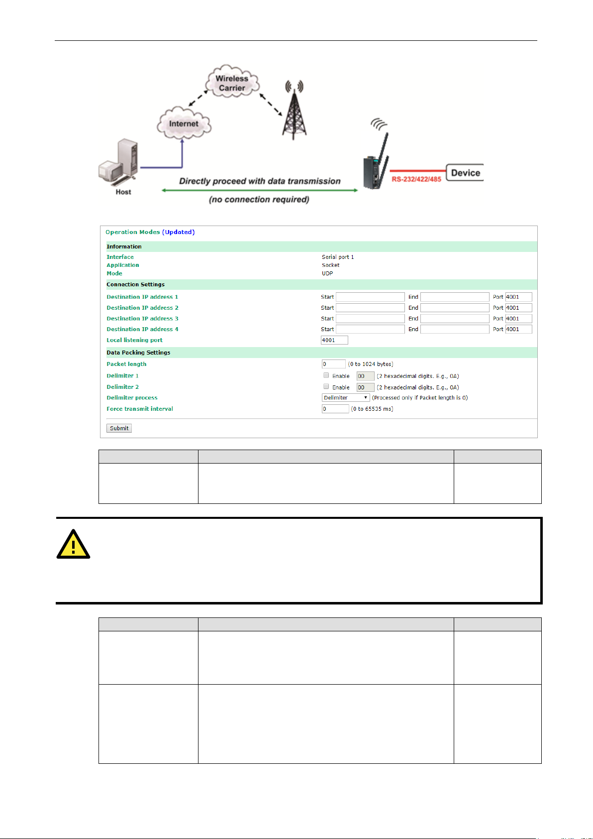
OnCell 3120-LTE-1 Web Console Configuration
3-33
In UDP mode, you may specify up to 4 ranges of IP addresses
ATTENTION
The maximum selectable IP address range is 64 addresses. However, when using multicast, you may enter
IP addresses of the form xxx.xxx.xxx.255 in the Begin field. For example, enter 192.168.127.255 to allow
the OnC
192.168.127.254.
1 listens to and
known UDP ports, the default is
Setting Description Factory Default
Destination address
1 through 4
ell 3120-LTE-1 to broadcast UDP packets to all hosts with IP addresses between 192.168.127.1 and
Setting Description Factory Default
Local listen port This is the UDP port that the OnCell 3120-LTE-
Packing length The Packing length setting refers to the maximum amount
for the serial port to connect to. At least one destination
range must be provided.
that other devices must use to contact the OnCell 3120-LTE-
1. To avoid conflicts with well-
set to 4001.
of data that is allowed to accumulate in the serial port buffer
before sending. At the default of 0 for packet length, no
maximum amount is specified and data in the buffer will be
sent as specified by the delimiter settings or when the buffer
is full. When a packet length between 1 and 1024 bytes is
None
4001
0
Page 47

OnCell 3120-LTE-1 Web Console Configuration
3-34
specified, data in the buffer will be sent as soon it reaches the
characters act as the delimiter to control when data should be
ATTENTION
In order to enable a delimiter, packet length must be set to 0.
conjunction with
delimiter is enabled, the OnCell 3120
exceeds 1 KB.
Setting Description Factory Default
specified length.
Delimiter 1
Delimiter 2
When Delimiter 1 is enabled, the serial port will queue the
data in the buffer and send the data to the Cellular or
Ethernet port when a specific character, entered in hex
format, is received. A second delimiter character may be
enabled and specified in the Delimiter 2 field, so that both
sent.
00
Setting Description Factory Default
Delimiter process The Delimiter process field determines how the data is
Force transmit This parameter defines how large a gap in serial
Delimiter 1 and never on its own; otherwise there may be data errors. Even when a
-LTE-1 will still pack and send the data when the amount of data
handled when a delimiter is received. Delimiter 1 must be
enabled for this field to have effect. If Delimiters 1 and 2 are
both enabled, both characters must be received for the
delimiter process to take place.
• Delimiter: Data in the buffer will be transmitted when the
delimiter is received.
• Delimiter + 1: Data in the buffer will be transmitted after 1
additional byte is received following the delimiter.
• Delimiter + 2: Data in the buffer will be transmitted after 2
additional bytes are received following the delimiter.
• Strip Delimiter: Data in the buffer is first stripped of the
delimiter before being transmitted.
communication the OnCell 3120-LTE-1 will allow before
packing the serial data in its internal buffer for network
transmission.
As data is received through the serial port, it is stored by the
OnCell 3120-LTE-1 in the internal buffer. The OnCell 3120-
LTE-1 transmits the data stored in the buffer via TCP/IP when
the internal buffer is full or as specified by the force-transmit
time.
When this field is set to 0, the force transmit time is disabled
and transmission is determined solely by the data in the
internal buffer. When the force transmit time is set to a value
from 1 to 65535, the TCP/IP protocol software will pack the
serial data received for transmission after the gap in serial
communication exceeds the specified force transmit time.
The optimal force-transmit time setting depends on your
application. However, it must be set to a value that is more
than one-character interval within the specified baudrate. For
example, assume that the serial port is set to 1200 bps, 8
data bits, 1 stop bit, and no parity. In this case, the total
number of bits needed to send a character is 10 bits, and the
time required to transfer one character is (10 (bits) / 1200
Delimiter 2 should only be enabled in
Delimiter
0 ms
Page 48

OnCell 3120-LTE-1 Web Console Configuration
3-35
Setting Description Factory Default
(bits/s)) × 1000 (ms/s) = 8.3 ms. Therefore, you should
set the force transmit time to be greater than 8.3 ms, so in
this case, it must be greater than or equal to 10 ms.
If it is necessary to send a series of characters in the same
packet, the serial device will need to send that series of
characters within the specified force transmit time, and the
total length of data must be less than or equal to the OnCell
3120-LTE-1’s internal buffer size (1 KB per port).
Types of UDP Connection
Fixed Public IPs for both OnCell and Host PC
If your cellular service provider offers a fixed public IP address after you connect to the cellular network,
you can access the OnCell 3120-LTE-1 from a host PC that has a fixed public IP.
Domain name with DDNS
If your cellular service provider assigns a public IP address after you connect to the cellular network, you
can also access the OnCell 3120-LTE-1 using the domain name. If your service provider assigns a public IP
address (either fixed or dynamic) to your cellular device and your control center is the side that initiates the
connection, you can enable the DDNS function and UDP mode to allow other devices on the Internet to
connect to your device using its domain name. This will ensure that your device will remain reachable even
when its public IP address is updated. Note that you will need to register your device with a DDNS server.
Please refer to Appendix B for more information.
Cellular Settings
This section describes the pages that you can use to configure cellular connection settings on the OnCell
3120-LTE-1:
• Cellular WAN Settings–Configure these settings to establish a cellular connection.
• GuaranLink Settings–Use this page to configure Moxa’s proprietary 4-tier link protection that ensures
reliable network connectivity.
• Auto IP Report Settings–If your service provider assigns a dynamic WAN IP address, you can
configure this screen to set the OnCell 3120-LTE-1 to automatically send its WAN IP address to a
specified host.
• OnCell Central Manager Settings–For details on the OnCell Central Manager setting, refer to the
OnCell Central Manager User’s Manual available at www.moxa.com.
Page 49

OnCell 3120-LTE-1 Web Console Configuration
3-36
Cellular WAN Settings
Configure the fields in the Cellular WAN Settings page to establish a 2G/3G/4G connection with a service
provider.
The OnCell 3120-LTE-1 provides you with a scheduling function for managing your cellular connection.
Depending on your application, you can use the scheduling function to specify when the radio should be
turned on/off, when to disconnect the data transmission, or go into SMS-only mode and enable data
transmission only during emergencies.
If you install two SIM cards in the OnCell 3120-LTE-1, you can select the Dual SIM mode and enable the
GuaranLink feature to enable the OnCell 3120-LTE-1 to regularly check the connection quality and perform
an automatic switchover in case the cellular connection is down. This setting ensures operation redundancy.
Field Description Default setting
SIM Select a connection mode from the drop-down list.
SIM 1—Select this option to establish a cellular connection using
the SIM card installed in the SIM 1 slot.
SIM 2—Select this option to establish a cellular connection using
the SIM card installed in the SIM 2 slot.
Dual SIM—Select this option if you want the OnCell 3120-LTE-1 to
automatically establish a cellular connection using any one of the
SIM cards. If you select the Dual SIM options, enable the
GuaranLink feature to ensure optimum link quality and operation
redundancy.
SIM 1
Field Description Default setting
SIM 1 PIN
SIM 2 PIN
If configured, enter the PIN (numeric with up to 7 digits) to unlock
the SIM card.
Note: A SIM card becomes locked if you enter an incorrect PIN
more than three times.
N/A
Page 50

OnCell 3120-LTE-1 Web Console Configuration
3-37
Field Description Default setting
SIM 1 band
SIM 2 band
SIM 1 Service
Provider
SIM 2 Service
Provider
SIM 1 username
SIM 2 username
SIM 1 password
SIM 2 password
SIM 1 APN
SIM 2 APN
SIM 1
authentication
type/
SIM 2
authentication
type
Select Auto to have the OnCell device automatically negotiate
with the base station for the optimum cellular band frequency.
Select Manual for the OnCell device to use a specific cellular band
frequency.
Note: The OnCell device does not establish a cellular connection if
your service provider does not support any of the bands you have
selected.
For OnCell 3120-LTE-1-EU/AU models, you do not need to select a
service provider.
For the OnCell 3120-LTE-1-US model, select a service provider for
the SIM card.
If configured, enter the username for authentication with your
service provider.
If configured, enter the password for authentication with your
service provider. The length of the password can be up to 31
characters.
Your service provider may use access point network (APN)
information to provide different service levels.
If configured, enter the access point network (APN) information.
Select Auto if you want the OnCell device to automatically select
either PAP or CHAP authentication method when setting up a data
session.
Select PAP (Password Authentication Protocol) to send user name
and password to the server and verify that the user name and
password match with the server database.
Select CHAP (Challenge-Handshake Authentication Protocol) if the
identifiers are changed frequently and if authentication can be
requested by the server at any time. CHAP provides more security
than PAP.
Auto
OTHERS
N/A
N/A
N/A
Auto
GuaranLink
A number of factors can contribute to connection failures for cellular communications, including loss of
cellular signal, interference, connection error caused by the base station, and termination by the operator
for unknown reasons. Moxa’s proprietary GuaranLink feature, which is different from the basic heartbeat
function, enables reliable connectivity with 4-tier intelligent connection checks without sending excessive
and costly cellular packets.
GuaranLink Recovery Process for Dual SIM Connections
The GuaranLink feature in OnCell 3120-LTE-1 automatically tries to re-establish a connection when a
connection failure occurs by performing one of the following actions depending on the number of SIM cards
enabled in the device:
• One SIM card: GuaranLink resets the cellular module without rebooting the device to force negotiation
between the OnCell 3120-LTE-1 and the base station.
• Dual SIM cards: When the preferred SIM card fails to establish a connection, GuaranLink resets the
cellular module without rebooting the device and establishes a cellular connection using the second SIM
card account.
• If SIM 1 is chosen but SIM card is installed only in SIM 2 slot, no action will be performed. Please ensure
that a SIM card is installed in the SIM card slot that you have selected for operation.
Page 51

OnCell 3120-LTE-1 Web Console Configuration
3-38
• If one of the SIM cards is not readable, GuaranLink will automatically force a cellular connection using
the other SIM card account. The system log will record this event. If the second SIM card also cannot be
read, GuaranLink will not try again.
GuaranLink Settings
In the navigation panel, click Cellular Settings > GuaranLink Settings to display the configuration
screen.
ISP Initial Connection Check (Default)
Data Session Retry (Default)
The following table describes the fields:
Field Description Default setting
GuaranLink Select Enable to activate the GuaranLink feature.
For operation redundancy, enable GuaranLink with Dual SIM
mode so that the OnCell 3120-LTE-1 regularly checks the
connection quality and performs an automatic switchover in case a
cellular connection is down.
Select Disable to deactivate the GuaranLink feature.
Register to
network timeout
This field is used by the ISP initial connection check.
Enter the time period (10–600 minutes) that the OnCell 3120-LTE-
1 must wait before terminating the connection to an ISP and
starting the GuaranLink recovery process.
Enable
10
Page 52

OnCell 3120-LTE-1 Web Console Configuration
3-39
Data session retry
Field Description Default setting
Enter the number of times (1 to 5; default is 3) the OnCell 3120-
count
Auto reboot Select Enable to activate the auto reboot function. If the network
Module recovery
retry count
DNS/Ping remote
host 1/2
ISP initial
connection check
LTE-1 is to request an IP address from the ISP.
If the OnCell 3120-LTE-1 fails to obtain an IP address after 3 tries
(default value), it starts the GuaranLink recovery process. The
time interval between each retry is 3 minutes.
does not recovery after resetting the module a certain number of
times, this function reboots the device to recovery the system.
Enter the number of times (4 to 30) the OnCell 3120-LTE-1 is to
reset the module to recovery the network. If the OnCell 3120-LTE-
1 fails to recovery the network after 5 retries (default value), it
reboots the device to recovery the system.
This field is used for cellular connection alive and packet-level
connection checks.
Enter the IP address or domain name of a remote host to ping or
for a DNS lookup test. To ensure accurate checks, we suggest
entering the host domain name here. For details, refer to Packet-
level connection check action.
Select Enable to set the OnCell 3120-LTE-1 to complete the
registration process to a base station before the timeout specified
in the Register to network timeout field.
If the OnCell 3120-LTE-1 fails to register to the base station within
the timeout period, it starts the GuaranLink recovery process.
Select Disable to allow the OnCell 3120-LTE-1 to wait until base
station registration is successful.
3
Enable
5
N/A
Disable
Cellular Connection Alive Check (Default)
Packet-Level Connection Check (Default)
Page 53

OnCell 3120-LTE-1 Web Console Configuration
3-40
cellular connection alive by performing a DNS lookup or remote
ither the DNS server or the
Transmission Connection Check (Default)
Field Description Default setting
Cellular connection
alive check
Cellular connection
alive check interval
Cellular connection
alive check retry
count
Packet-level
connection check
Packet-level
connection check
action
Packet-level
connection check
interval
Packet-level
connection check
retry count
Depending on your ISP, cellular connection is terminated if
there is no active data transmission for a certain period of
time.
Select Enable to set the OnCell 3120-LTE-1 to keep the
host Ping (host 1 is checked first; if the check fails, host 2 is
checked), if no data is transmitted within the timeout period.
For details, check the Packet-level connection check
action.
If the connection check fails after the number of retries
specified in the Cellular connection alive retry count field,
the OnCell 3120-LTE-1 starts the GuaranLink recovery process.
Enter the time (between 1 to 600 minutes) the OnCell 3120-
LTE-1 is to wait before performing a connection check.
Enter the number of times the OnCell 3120-LTE-1 is to try the
connection check with approximately 15-second time interval
between each retry.
If the connection check fails, the OnCell 3120-LTE-1 starts the
GuaranLink recovery process.
Select Enable to check whether the cellular network is
accessible using DNS lookup and remote host ping, regardless
of any existing data transmission.
If the connection check fails after the number of retries
specified in the Packet-level connection check retry count
field, the OnCell 3120-LTE-1 starts the GuaranLink recovery
process.
Select one of the following options to determine if the
connection check is successful:
• DNS and Ping – Response from both the DNS server and
remote host. If an IP address is entered, the OnCell device
will ping the IP to check the connection. If a host name is
entered, the OnCell will check the DNS and also ping the
host IP.
• DNS or Ping – Response from e
remote host. If an IP address is entered, the OnCell device
will ping the IP to check the connection. If a host name is
entered, the OnCell will only check the DNS.
Enter the time (between 1 to 600 minutes) the OnCell 3120-
LTE-1 is to wait before performing a connection check.
Enter the number of times the OnCell 3120-LTE-1 is to try the
connection check (with approximately 15 seconds between
each retry) before re-establishing the connection.
Disable
5
3
Disable
DNS and Ping
5
3
Page 54

OnCell 3120-LTE-1 Web Console Configuration
3-41
Field Description Default setting
Transmission
connection check
Transmission
connection alive
check interval
If a remote system regularly monitors connection to the OnCell
3120-LTE-1, select Enable to set the OnCell 3120-LTE-1 to
receive polling information from the remote system at regular
intervals.
If no polling information is received within the timeout period,
the OnCell 3120-LTE-1 starts the GuaranLink recovery process.
Enter the time (between 1 to 600 minutes) the OnCell 3120-
LTE-1 is to wait for polling information from a remote system
before starting the GuaranLink recovery process.
Disable
5
Page 55

OnCell 3120-LTE-1 Web Console Configuration
3-42
Auto IP Report Settings
In MDVPN (mobile data virtual private network) applications where service providers set up private VPNs for
enterprise customers, a cellular gateway must be assigned IP address that is visible to a remote host in a
central office. In cases where a service provider assigns dynamic IP addresses, you can configure the Auto
IP Report Settings screen to set the OnCell 3120-LTE-1 to regularly send its WAN IP address to a remote
host.
The following table describes the fields.
Field Description Default setting
Auto IP report to
host
Report to UDP port Enter the listing port number on the remote host. 63100
Report period Enter the number of minutes the OnCell 3120-LTE-1 is to
Enter the IP address of a remote host to which the OnCell
3120-LTE-1 is to send the WAN IP address information.
wait before sending WAN IP address information.
N/A
99
Auto IP Report Format
The OnCell packet follows the "Type Length Value" format.
Type Length Value
1 byte 1 byte Length bytes
The following table shows the Auto IP report format:
“Moxa”, 4 bytes Info[0] Info[1] ... Info[n]
Info [n]
Field ID Length Data
Length a 1 Variable, Length is “Length Field”
ID List
ID Value Description Length Note
1 Server Name Variable ASCII char
2 Hardware ID 2 Little-endian
3 MAC Address 6 6-byte MAC address. If the MAC address is “00-90-
E8-01-02-03” then MAC[0] is 0, MAC[1] is
0x90(hex), MAC[2] is 0xE8(hex), etc.
4 Serial Number 4, DWORD Little-endian
5 IP Address 4, DWORD Little-endian (LAN IP)
9 AP ID 4, DWORD Little-endian
10 IP Address2 4, DWORD Little-endian (WAN IP)
11 Signal Level 1 Unsigned char
12 RSSI 1 Unsigned char
Page 56

OnCell 3120-LTE-1 Web Console Configuration
3-43
Example:
ID Value Length Note
05 04 C0,a8,81,71
09 04 30,12,19,89
0a 04 C0,a8,81,71
---- ---- ----
OnCell Central Manager Settings
For the OnCell Central Manager settings, refer to the OnCell Central Manager User’s Manual, which can be
downloaded from www.moxa.com.
Advanced Settings
Several advanced functions are available to increase the functionality of your OnCell 3120-LTE-1 and
wireless network system. The DHCP server helps you deploy wireless clients efficiently. Packet filters
provide security mechanisms, such as firewalls, in different network layers. And, SNMP support can make
network management easier.
DHCP Server
DHCP (Dynamic Host Configuration Protocol) is a networking protocol that allows administrators to assign
temporary IP addresses to network computers by “leasing” an IP address to a user for a limited amount of
time, instead of assigning permanent IP addresses.
The OnCell 3120-LTE-1 can act as a DHCP server and assign IP addresses to your DHCP clients by
responding to DHCP requests from the clients. The IP-related parameters you set on this page will also be
sent to the client.
You can also assign a static IP address to a specific client by entering its MAC address. The OnCell 3120-
LTE-1 provides a Static DHCP mapping list with up to 16 entities. Be reminded to check the Active check
box for each entity to activate the setting.
You can check the IP assignment status in the DHCP Client List screen (click Status > DHCP Client List).
Page 57

OnCell 3120-LTE-1 Web Console Configuration
3-44
as a DHCP server.
Primary/Secondary
Enter the number (between 1 and 999) of IP address to assign
The following table provides the field descriptions:
Field Description Default setting
DHCP server Select Enable to set the OnCell 3120-LTE-1
Select Disable to set the OnCell 3120-LTE-1 as a DHCP client.
Default gateway Enter the IP address of the default gateway that connects to
an outside network.
Subnet mask Enter the subnet mask to specify the type of network for the
DHCP clients.
Enter the IP address of the primary or secondary DNS server.
DNS server
Start IP address Enter the starting IP address in the IP address pool. N/A
Maximum number
of users
Client lease time Enter the lease time (between 1 to 10 days) for an assigned
Static DHCP
Mapping
After you specify a DNS server, you can access a web site by
entering its URL instead of the IP address.
to DHCP clients.
IP address. The IP address expired after the lease time.
Local IP address and the MAC address of the connected
devices (up to 16 devices) that obtain their IP address
through DHCP.
Disable
N/A
N/A
N/A
N/A
10
N/A
Page 58

OnCell 3120-LTE-1 Web Console Configuration
3-45
DDNS
If a DHCP server assigns an IP address to the OnCell 3120-LTE-1, you can configure dynamic DNS (DDNS)
setting on the OnCell 3120-LTE-1 to allow remote servers to access the OnCell 3120-LTE-1 using its domain
name instead of IP address. For more information on DDNS, see Appendix C.
Click Advanced Settings > DDNS to display the configuration screen.
The following table provides the field descriptions:
Field Description Default setting
DDNS function Select Enable to activate the DDNS feature. Disable
Service provider Select an option from the drop-down list. N/A
Host name Enter the host name that you created with the service provider. N/A
Username Enter the username for update authentication. N/A
Password Enter the password for update authentication. N/A
Packet Filters
The OnCell 3120-LTE-1 includes various filters for IP-based packets going through LAN and WLAN
interfaces. You can set these filters as a firewall to help enhance network security.
MAC Filter
The OnCell 3120-LTE-1’s MAC filter is a policy-based filter that can allow or filter out IP-based packets with
specified MAC addresses. The OnCell 3120-LTE-1 provides 32 entities for setting MAC addresses in your
filtering policy. Remember to check the Active check box for each entity to activate the setting.
Page 59

OnCell 3120-LTE-1 Web Console Configuration
3-46
ATTENTION
Be careful when you enable the filter function:
Drop
Accept
ATTENTION
Be careful when you enable the filter function:
Drop
Accept
Field Description Default setting
MAC filters
function
Policy Select Accept to allow packets that meet the specified criteria.
Select Enable to enable MAC filtering. Disable
Drop
Select Drop to deny packets that meet the specified criteria.
+ “no entity on list is activated” = all packets are allowed
+ “no entity on list is activated” = all packets are denied
IP Protocol Filter
The OnCell 3120-LTE-1’s IP protocol filter is a policy-based filter that can allow or filter out IP-based packets
with specified IP protocol and source/destination IP addresses.
The OnCell 3120-LTE-1 provides 32 entities for setting IP protocol and source/destination IP addresses in
your filtering policy. Four IP protocols are available: All, ICMP, TCP, and UDP. You must specify either the
Source IP or the Destination IP. By combining IP addresses and netmasks, you can specify a single IP
address or a range of IP addresses to accept or drop. For example, “IP address 192.168.1.1 and netmask
255.255.255.255” refers to the sole IP address 192.168.1.1. “IP address 192.168.1.1 and netmask
255.255.255.0” refers to the range of IP addresses from 192.168.1.1 to 192.168.1.255. Remember to
check the Active check box for each entity to activate the setting.
Field Description Default setting
IP protocol
filters function
Policy Select Accept to allow packets that meet the specified criteria.
+ “no entity on list is activated” = all packets are allowed.
+ “no entity on list is activated” = all packets are denied.
Select Enable to enable IP protocol filtering. Disable
Drop
Select Drop to deny packets that meet the specified criteria.
TCP/UDP Port Filter
The OnCell 3120-LTE-1’s TCP/UDP port filter is a policy-based filter that can allow or filter out TCP/UDP-
based packets with a specified source or destination port.
The OnCell 3120-LTE-1 provides 32 entities for setting the range of source/destination ports of a specific
protocol. In addition to selecting TCP or UDP protocol, you can set either the source port, destination port,
or both. The end port can be left empty if only a single port is specified. Of course, the end port cannot be
larger than the start port.
Page 60
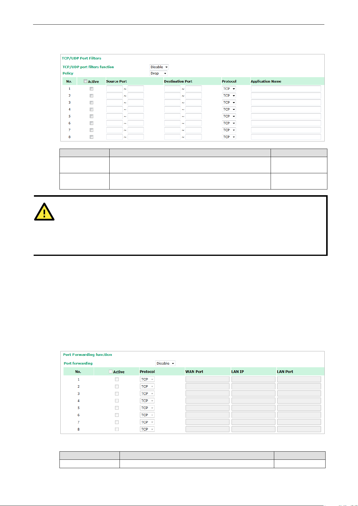
OnCell 3120-LTE-1 Web Console Configuration
3-47
ATTENTION
Be careful
Drop
Accept
OnCell device itself is NOT included within this policy.
For device interface access and security settings, go to
The Application name is a text string that describes the corresponding entity with up to 31 characters.
Remember to check the Active check box for each entity to activate the setting.
Field Description Default setting
TCP/UDP port
filters function
Policy Select Accept to allow packets that meet the specified criteria.
Select Enable to enable TCP/UDP port filtering. Disable
Drop
Select Drop to deny packets that meet the specified criteria.
when you enable the filter function:
+ “no entity on list is activated” = all packets are allowed
+ “no entity on list is activated” = all packets are denied
Port Forwarding Function
You can configure port forwarding settings on the OnCell 3120-LTE-1 to redirect specific packets from a
remote host on the WAN to a server on the LAN. This feature hides the IP address of a local server and
prevents remote hosts from accessing the local server directly.
The OnCell 3120-LTE-1 filters out unrecognized packets to protect your LAN network when computers
connected to the OnCell 3120-LTE-1 are not visible to the WAN.
To access the Port Forwarding settings, select Advanced Setup > Port Forwarding function. The
OnCell 3120-LTE-1 supports a total of 32 port-forwarding rules.
Maintenance Console settings.
The following table includes the field descriptions:
Field Description Factory Default
Port forwarding Select Enable to activate the port forwarding feature. Disable
Page 61

OnCell 3120-LTE-1 Web Console Configuration
3-48
Active Select this check box to activate the port forwarding entry. unchecked
Protocol Select an option from the drop-down list. TCP
WAN Port Enter the WAN port number.
Make sure that the port number specified is not already used
by other operation modes.
LAN IP Enter the IP address of a LAN device to receive the redirected
traffic.
LAN Port Enter the port number on a LAN device to which to redirect
the traffic to.
N/A
N/A
N/A
SNMP Agent
The OnCell 3120-LTE-1 supports SNMP V1/V2c/V3. SNMP V1 and SNMP V2c use a community string match
for authentication, which means that SNMP servers access all objects with read-only or read/write
permissions using the community string
select an authentication level of MD5 or SHA, is the most secure protocol. You can also enable data
encryption to enhance data security.
The OnCell 3120-LTE-1’s MIB is available for download from Moxa’s official website and supports reading the
attributes via SNMP (only the SNMP GET method is supported.)
public/private (default value). SNMP V3, which requires you to
SNMP security modes and security levels supported by the OnCell 3120-LTE-1 are shown in the following
table. Select the security mode and level that will be used to communicate between the SNMP agent and
manager.
Protocol
Version
SNMP
V1, V2c
SNMP V3 No-Auth No No Use account with admin or user to access
Setting on
UI web page
V1, V2c Read
Community
V1, V2c
Write/Read
Community
MD5 or SHA Authentication
MD5 or SHA Authentication
Authentication
Type
Community string No Use a community string match for
Community string No Use a community string match for
based on MD5 or
SHA
based on MD5 or
SHA
Data
Encryption
No Provides authentication based on HMAC-MD5,
Data
encryption
key
Method
authentication
authentication
objects
or HMAC-SHA algorithms. 8-character
passwords are the minimum requirement for
authentication.
Provides authentication based on HMAC-MD5 or
HMAC-SHA algorithms, and data encryption
key. 8-character passwords and a data
encryption key are the minimum requirements
for authentication and encryption.
Page 62

OnCell 3120-LTE-1 Web Console Configuration
3-49
The following parameters can be configured on the SNMP Agent page.
Field Description Default Setting
SNMP agent Select Enable to activate SNMP agent. Disable
Remote
management
Read community Enter the community string or password (up to 31 characters
Write
community
SNMP agent
version
Admin
authentication
type
Authentication
username
Admin
encryption
method
Private key Enter the key (up to 63 characters) for data encryption N/A
Private MIB
information
Device object ID
Select Enable to allow remote management via SNMP agent. Disable
public
long) for an SMNP agent to access objects with read-only
permission.
Enter the community string or password (up to 31 characters
long) for an SMNP agent to access objects with read-write
permission.
Select the SNMP protocol version used to manage the OnCell
3120-LTE-1.
Select No Auth to use an administrator account to access
objects without authentication.
Select MD5 to authenticate using HMAC-MD5 algorithms where
the minimum requirement is to use an 8-character password.
Select SHA to authenticate using HMAC-SHA algorithms where
the minimum requirement is to use an 8-character password.
The username to use for SNMP authentication admin
Select Disable for no data encryption
Select DES to use DES-based data encryption
Select AES to use AES-based data encryption
The object ID (OID) is the enterprise value for the OnCell 3120-
LTE-1. This value is not configurable.
private
V1, V2c
No Auth
Disable
N/A
Page 63
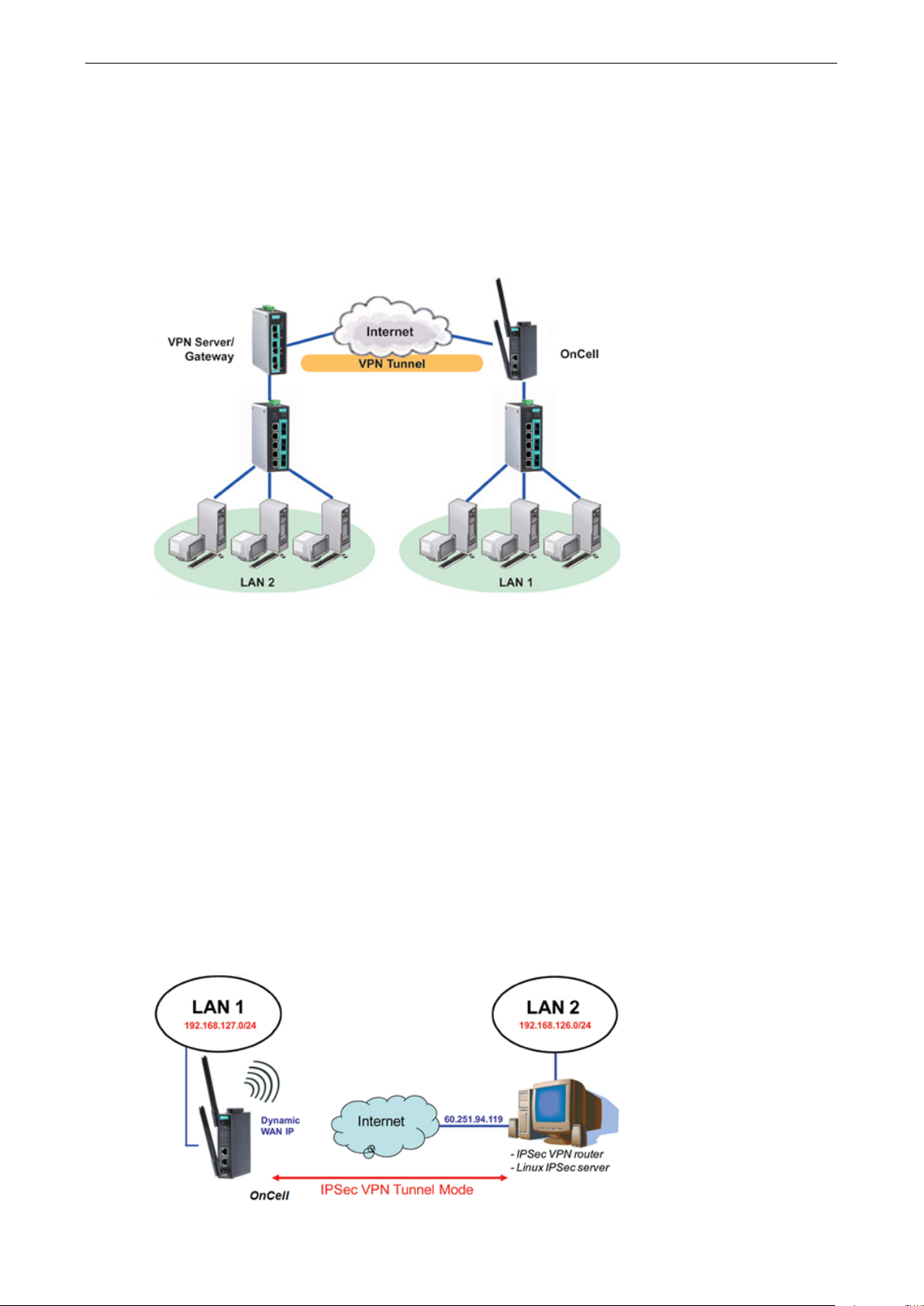
OnCell 3120-LTE-1 Web Console Configuration
3-50
VPN
Computers that are part of a virtual private network (VPN) use a second, “virtual” IP address to connect to
the Internet. Instead of running across a single private network, some of the links between nodes that are
part of a VPN use open network connections or virtual circuits on a larger network, such as the Internet. The
OnCell 3120-LTE-1 can act as a VPN client or VPN server. Once the connection is established, cellular
devices can communicate with other network devices on the same private network.
The following figure shows an example of a network topology:
IPsec
Overview—OnCell 3120-LTE-1 IPsec Feature
The IPsec feature on the OnCell 3120-LTE-1:
• Provides Layer-3 (IP-layer) security in a network with gateway-to-gateway topology as illustrated in the
following figure
• Initiates a VPN connection from the OnCell 3120-LTE-1 to a VPN Server
• Operates in Tunnel mode with IPsec VPN tunnel:
Manual Key/ESP, IKE/PSK encryption
DES/3DES/AES128 encryption
MD5/SHA1 authentication
• Provides IPsec NAT traversal and PFS (perfect forwarding secrecy)
• Provides IPsec over GRE protocol
Page 64

OnCell 3120-LTE-1 Web Console Configuration
3-51
IPsec Settings
You can enable or disable the IPsec and NAT traversal functions and configure up to five VPN tunnels by
selecting Advanced Settings > VPN > IPsec Settings.
The following table provides the field descriptions.
Field Description Factory Default
IPsec Select Enable to activate the IPsec feature. Disable
NAT Traversal Select Enable to activate the NAT traversal feature that
allows IPsec traffic to traverse through NAT-enabled devices.
Make sure that the remote VPN device supports this feature.
Action Click Edit to configure a VPN tunnel.
Click Delete to remove the selected VPN tunnel.
Disable
Configuring a VPN Tunnel
To configure a VPN tunnel, click Edit in the IPsec Settings screen.
Page 65

OnCell 3120-LTE-1 Web Console Configuration
3-52
The following table provides the field descriptions:
Field Description Factory Default
IPsec enable Select Enable to activate the VPN tunnel. Disable
Connection name Enter a descriptive name for the VPN tunnel. -
Connection type Select one of the following connection types:
• Site-to-Site – Select this option to create a VPN tunnel
for static local and remote subnets.
• Site-to-Site (any) – Select this option to create a VPN
tunnel between a static local subnet and a dynamic
remote subnet.
Startup mode Select Start in Initial to set the OnCell 3120-LTE-1 to
initiate a connection with the remote VPN gateway.
Select Wait for Connecting to set the OnCell 3120-LTE-1 to
wait for a remote VPN gateway to initiate a connection.
Remote VPN
gateway
Local network Enter the IP of the local network. N/A
Local netmask Enter the netmask of the local network. N/A
Local ID Enter an ID (IP/FQDN/User_FQDN) to identify and
Remote network Enter the IP of the remote network. N/A
Remote netmask Enter the netmask of the remote network. N/A
Remote ID Enter an ID (IP/FQDN/User_FQDN) to identify and
NAT type Select this check box to activate 1:1 or 1:N network address
GRE enable Enables generic routing encapsulation (GRE) in IPsec
Enter the WAN IP address of the remote VPN gateway. N/A
authenticate the local VPN gateway.
authenticate the remote VPN endpoint.
translation (NAT)
Local 1:1 NAT—Virtual IP addresses are used for
communication via the VPN tunnel. These addresses are
linked to the real IP addresses for the network that has been
connected. The subnet mask remains unchanged.
Local 1:N NAT—The device has one IP address, which can be
used to access the device externally. For incoming data
packets, the device can convert the specified sender WAN
port to internal IP address. For example, this function can be
used to enable PLCs from different sites to have the same IP
address.
tunneling.
Site-to-Site
Start in Initial
N/A
N/A
None
Disable
Page 66

OnCell 3120-LTE-1 Web Console Configuration
3-53
connecting to the remote gateway when the VPN tunnel is not
Field Description Factory Default
Key Exchange (Phase1)
Operation mode Select main mode or aggressive mode to configure the
standard negotiation parameters for IKE Phase 1 of the VPN
Tunnel.
Authentication mode Select Pre-shared key, RSA Signature, or X.509
authentication mode to for phase 1 key exchange.
The configuration fields vary depending on the authentication
mode you select. For information on configuring each
authentication mode, refer to the respective sections in this
guide.
Encryption
algorithm
Hash algorithm Select the MD5 or SHA-1 VPN key exchange phase 2 hash
DH group Select the DH-2(1024) or DH-5(1536) VPN key exchange
Negotiation times The number of allowed reconnect times when startup mode is
Select the DES, 3DES or AES128 algorithm for the VPN
ISAKMP phase 1 encryption mode.
mode.
phase 1 Diffie-Hellman group. As the Diffie-Hellman Group
number increases, the higher the level of encryption
implemented for PFS.
initiated. If the number is 0, this tunnel will always try
Main
Pre-shared key
3DES
MD5
DH-2
0
created successfully.
IKE life time Enter the number of minutes for the VPN IKE SA phase 1
Lifetime. This is the period of time to pass before establishing
a new IPsec security association (SA) with the remote
endpoint.
Rekey expire time Enter the number of minutes for the Start to Rekey before
IKE lifetime expired.
60
9
Page 67

OnCell 3120-LTE-1 Web Console Configuration
3-54
Field Description Factory Default
Rekey fuzz percent The rekey expire time will change randomly to enhance the
security. Rekey fuzz percent is the maximum random change
margin of the Rekey expire time. 100% means the rekey
expire time will not change randomly.
Data Exchange (phase2)
Perfect forward
secrecy
SA life time Enter the number of seconds for the VPN ISAKMP phase 2
Encryption
algorithm
Hash algorithm Select the MD5 or SHA-1 VPN ISAKMP phase 1 authentication
Dead Peer Detection
DPD action When you enable the Dead Peer Detection (DPD) feature, the
DPD delay The period of dead peer detection messages. 30
DPD timeout Timeout to check if the connection is alive or not. 120
Enable or disable the Perfect Forward Secrecy. PFS is an
additional security protocol.
Lifetime. This is the period of time to pass before establishing
a new IPsec security association (SA) with the remote
endpoint.
Select the DES, 3DES, or AES128 algorithm for the VPN
ISAKMP phase 1 encryption mode.
mode.
OnCell 3120-LTE-1 performs one of the following actions
when connection to a remote IPsec tunnel is down:
• Hold: Keep the VPN tunnel
• Clear: Clear the VPN tunnel
• Restart: Re-establish the VPN tunnel on Start in Initial
mode.
• Restart by Peer: Re-establish the VPN tunnel on Wait for
connecting mode.
100%
Disable
480
3DES
MD5
Disable
Configuring Pre-Shared Key Settings
To configure pre-shared key authentication mode in phase 1 key exchange, in the Tunnel settings screen,
select Pre-shared key from the Authentication mode drop-down list. Then, enter a key in the text field.
Make sure that you configure the same key on the OnCell 3120-LTE-1 and the remote VPN gateway.
Configuring RSA Signature Settings
To configure RSA signature settings, complete the following steps:
1. In the Tunnel Settings screen, select RSA Signature from the Authentication mode drop-down list.
2. Generate or import a local private key. Perform one of the following actions:
• Click Generate Local Private Key. The OnCell 3120-LTE-1 creates a private key and displays the
key information in the Local private key field.
• Click Import Local Private Key and select a key file to import. After the OnCell 3120-LTE-1
successfully imports the selected key, the system displays the key information in the Local private
key field.
3. Generate or import a remote private key. Perform one of the following actions:
• Click Generate Remote Public Key. The OnCell 3120-LTE-1 creates a public key and displays the
key information in the Remote public key field.
• Click Import Remote Public Key and select a key file to import. After the OnCell 3120-LTE-1
successfully imports the selected key, the system displays the key information in the Remote public
key field.
Page 68
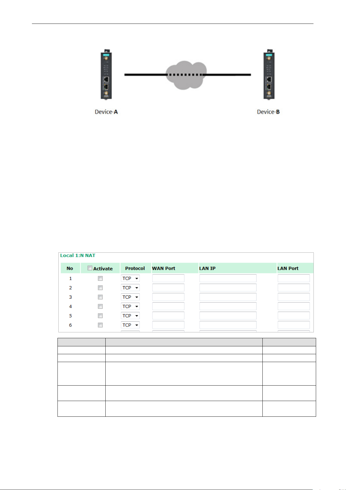
OnCell 3120-LTE-1 Web Console Configuration
3-55
The following figure shows the certificate generation and certificate export/import example.
Generate Root CA
Generate Local Certificate
Click PKCS#12 Export to export the local
certificate (local_CA_A.p12)
Click Certificate Export to export the local
certificate file (local_CA_A.pem)
Click VPN > X.509 >Local Certificate Upload
and import the local certificate
(local_CA_A.p12).
Click VPN > X.509 > Remote Certificate
Upload to import the remote certificate
(local_CA_B.pem).
1. Generate Root CA
2. Generate Local Certificate
3. Click PKCS#12 Export to export the local
certificate (local_CA_B.p12)
4. Click Certificate Export to export the local
certificate file (local_CA_B.pem)
5. Click VPN > X.509 >Local Certificate Upload
and import the local certificate
(local_CA_B.p12).
6. Click VPN > X.509 > Remote Certificate
Upload to import the remote certificate
(local_CA_A.pem).
Local 1:N NAT
OnCell 3120-LTE-1 can support up to 32 TCP/UDP connections for 1:N network address translation (NAT).
Field Description Default setting
Activate Select this check box to activate the 1:N NAT Always on
Protocol Select the protocol to use in the NAT policy. TCP
WAN Port Enter the WAN port number to redirect to specific LAN IP.
Make sure that the port number specified is not already used by
OP modes.
LAN IP Enter the IP address of a LAN device to receive the redirected
traffic.
LAN Port Enter the port number on a LAN device to which to redirect
traffic.
N/A
N/A
N/A
Page 69

OnCell 3120-LTE-1 Web Console Configuration
3-56
NOTE
Before you configure X.509 settings, make sure that you have imported local and remote certificates in the
Local/Remote Certificate Upload
Local/Remote Certificate Upload
1:N Concept
X.509 Certificate
screen (click Advanced Settings > VPN > X.509 Certificate >
).
In the Tunnel Settings screen, select X.509 from the Authentication mode drop-down list and select a
certificate from the Local certificate and Remote certificate drop-down lists.
Certificate Generation
X.509 is a digital certificate method commonly used for IPsec authentication. You can generate a self-signed
root CA or local certificate on the OnCell 3120-LTE-1 and import or export the certificate on a remote VPN
gateway.
Page 70

OnCell 3120-LTE-1 Web Console Configuration
3-57
To display the Certificate Generation screen, click Advanced Settings > VPN > X.509 Certificate >
Certificate Generation.
To generate a root CA certificate, complete the following steps:
1. In the Certificate Generation screen, enter information in the fields under Root Certificate
Generation.
Field Description
Certificate days Enter the number of days the certificate is valid for.
Certificate password Enter a password to create a password-protected certificate.
Country name Enter the country.
State or province name Enter the state or the province.
Locality name Enter the city.
Organization name Enter the name of the organization.
Organization unit name Enter the unit or section in the organization.
Common name Enter a name (such as a server name or your name).
Email address Enter an email address.
2. Click Generate Root CA.
Page 71
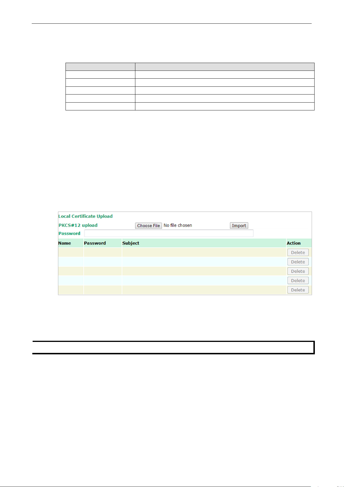
OnCell 3120-LTE-1 Web Console Configuration
3-58
NOTE
You can generate a local certificate in the
After you have generated the root CA certificate, generate a local certificate and export the key files.
Complete the following steps:
1. In the Certificate Generation screen, enter information in the fields under Local Certificate Settings.
Field Description
Certificate days Enter the number of days the certificate is valid for.
Certificate password Enter a password to create a password-protected certificate.
Organization unit name Enter the unit or section in the organization.
Common name Enter a name (such as a server name or your name).
Email address Enter an email address.
2. Click Generate Local Certificate.
3. Click Certificate Export to export the public key file for the certificate that you can import on to a
remote VPN gateway.
4. Click PKCS#12 Export to export the private key file for local certificates on the OnCell 3120-LTE-1.
You can import the local certificate in the Local Certificate Upload screen.
Local Certificate Upload
If you configure X.509 authentication mode for VPN tunnel setup, you must import a local certificate on the
OnCell 3120-LTE-1.
You can add or delete a local certificate in the Local Certificate Upload screen.
1. Click Advanced Settings > VPN > X.509 Certificate > Local Certificate Upload.
2. In the PKCS#12 upload field, click Choose File to select a local certificate file
3. In the Password field, enter the certificate password.
4. Click Import.
Certificate Generation screen.
Page 72

OnCell 3120-LTE-1 Web Console Configuration
3-59
Remote Certificate Upload
You can add or delete a certificate from the remote VPN gateway in the Remote Certificate Upload
screen.
1. Click Advanced Settings > VPN > X.509 Certificate > Remote Certificate Upload.
2. In the Remote certificate upload field, click Browse to select a local certificate.
3. Click Import.
OpenVPN
Overview—OnCell 3120-LTE-1 OpenVPN Feature
The OnCell 3120-LTE-1 OpenVPN:
• Provides SSL/TLS (layer-4) security in a network with gateway-to-gateway topology. It can create either
a layer-3 based IP tunnel (TUN), or a layer-2 based Ethernet (TAP) that can carry any type of Ethernet
traffic.
• Supports both server and client mode communication through TCP/UDP to transfer encrypt data
• Provides server mode to push the network behind the OnCell 3120-LTE-1 to the server site so as to
make end-to-end connection possible (Figure 1)
• Acts as an OpenVPN server to force gateway routing and redirect all external connections only through
the VPN server’s gateway. (Figure2)
• Enables the OnCell 3120-LTE-1 to act as an OpenVPN server to allow duplicate OpenVPN clients access
under the same account name. This also allows OpenVPN clients to communicate with each site. (Figure
3)
Page 73

OnCell 3120-LTE-1 Web Console Configuration
3-60
Page 74

OnCell 3120-LTE-1 Web Console Configuration
3-61
OpenVPN—Router Mode
Use this OpenVPN mode to connect two sites that are under different subnets (in Layer 3) and encrypt the
TCP/UDP package data transmission. Router mode cannot process broadcast or multicast frames.
OpenVPN—Bridge Mode
Use this OpenVPN mode to have two sites under the same subnet (in Layer 2) and encrypt IP packages
during data transmission.
Page 75

OnCell 3120-LTE-1 Web Console Configuration
3-62
Server Settings
Server Setting—TUN (Router Mode)
Setting Description Factory Default
OpenVPN Select Enable to activate the VPN tunnel. Disable
Interface Type Select OpenVPN tunnel connection by router mode or bridge
mode
Network IP This is the virtual network used for private communications
between server and client hosts. The first network address
will be assigned to the server virtual interface. The remaining
network addresses can optionally be assigned to the
connecting clients.
Netmask Enter the subnet netmask of virtual network. 255.255.255.0
Push network IP This is the network that will be accessible from the remote
endpoint. You may leave this blank if you don’t want to add a
route to the local network through this tunnel on the remote
machine. This is generally set to your LAN network.
Push netmask Enter the netmask of the network behind the VPN server. 255.255.255.0
Protocol Select the protocol to be used for VPN. UDP
Port number Enter the port number for TCP / UDP connection 1194
Encryption
algorithm
Hash algorithm Select the MD5 or SHA-1 VPN key exchange phase 1 hash
Select authentication mode for key exchange. The
configuration fields vary depending on the authentication
mode you select.
mode.
TUN (Router)
10.8.0.0
192.168.127.0
BlowFish CBC
SHA1
Page 76
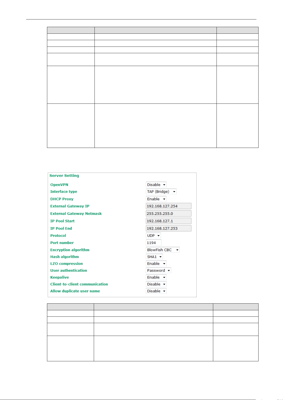
OnCell 3120-LTE-1 Web Console Configuration
3-63
Setting Description Factory Default
LZO compression Compress tunnel packets using the LZO algorithm Enable
User authentication Only password authentication is supported in server mode N/A
Keepalive Select Enable to check if the client connection is alive. Disable
Redirect to default
gateway
Client-to-client
communication
Allow duplicate user
name
Select Enable to force all clients generated traffic to pass
through the tunnel
Select Enable to allow communication between clients
connected to the server. Client-to-communication requires
Redirect to default gateway to be enabled.
If this function is disabled, the OnCell will only be able to
communicate with the server (see Figure 3: Client-to-Client
Communication above.)
Select Enable to allow multiple clients using the same
common name.
Note: There can only be one active session associated with a
user name at any given time. If another client with the same
common name connects, the previous client’s session will be
ended. This setting is not recommended but may be needed
in some scenarios.
Disable
Disable
Disable
Server Setting—TAP (Bridge Mode)
Setting Description Factory Default
DHCP Proxy Select Disable to activate the DHCP function. Disable
External Gateway IP Enter the remote site VPN serer gateway IP address. 192.168.127.254
External Gateway
Netmask
IP Pool Start This is the network that will access to remote VPN server
Enter the remote site VPN server subnet netmask. 255.255.255.0
192.168.127.1
and the IP range that can be assigned (clients number) in
this local network. The IP address entered here will be the
start IP for the local network (client).
Page 77

OnCell 3120-LTE-1 Web Console Configuration
3-64
NOTE
The Bridge mode is the recommended mode for multicast and broadcast
Setting Description Factory Default
IP Pool End The IP address entered here will be the end point of the IP
address for the local network (client).
192.168.127.253
requirements.
Server Certificate Upload
Setting Description
Root CA Browse your local drive and choose the certificate generated by X.509 then click
import to import the certificate.
PKCS#12 Upload Browse your local drive and choose the certificate with password which generated
by X.509 then click import to import the certificate.
Password Enter the password that you fill in X.509 password column.
Server CA The column shows the information of certification password and subject that
imported.
Server User Management
Enables management and export of user configurations.
Setting Description Factory Default
Edit Click Edit to open the User Management Settings window. -
Page 78

OnCell 3120-LTE-1 Web Console Configuration
3-65
User Active Select Enable to activate User accessibility Disable
User Name Enter User Name. N/A
Password Enter the password. N/A
Confirm
Password
Remote
Network
Remote
Netmask
Enter the password again. This must match the with the Password
field.
Enter the IP address of the remote network the user is connecting
from.
Enter the subnet mask of the remote network the user is
connecting from.
N/A
N/A
N/A
Server to User Config
Export the user configuration.
Client Settings
Setting Description Factory Default
Client enable Select Enable to activate OpenVPN Client Disable
Interface type Select OpenVPN tunnel connection by router mode or
bridge mode
Remote server IP This is the virtual network used for private communications
between this server and client hosts. The first network
address will be assigned to the server virtual interface. The
remaining network addresses can optionally be assigned to
the connecting clients. The remote site must assign a
server IP, public IP, or carrier private network that is
accessible to the clients.
TUN(Router)
10.8.0.0
Page 79

OnCell 3120-LTE-1 Web Console Configuration
3-66
NOTE
Before using the OpenVPN function, run an NTP check on the device to ensure that it is
the local time for proper authentication to take place.
Protocol Select the protocol to be used for VPN. UDP
Port number Enter the remote server port number for TCP / UDP
connection
Encryption
algorithm
Hash algorithm Select the MD5 or SHA-1 VPN key exchange phase 1 hash
LZO compression Compress tunnel packets using the LZO algorithm Enable
User authentication Select password or certification to protect the
User name Enter the user name for the client that you set on the
Password Enter the client password that you set on the server (up to
Select authentication mode for key exchange. The
configuration fields vary depending on the authentication
mode you select.
mode.
authentication choose either one
server.
15 characters.)
1194
BlowFish CBC
SHA1
password
N/A
N/A
Client Certificate Upload
Setting Description Factory Default
Root CA Browse your local drive or import a certificate code.
PKCS#12 Upload Browse your local drive or import a certificate code.
Password Default password “moxa” moxa
Client CA The column shows the client certification password and
X.509 Certificate
X.509 is a digital certificate method commonly used for OpenVPN authentication. You can generate a self-
signed root CA or local certificate on the OnCell 3120-LTE-1 and import or export the certificate on a remote
VPN gateway.
To display the Certificate Generation screen, click Advanced Settings > VPN > OpenVPN > X.509
Certificate > Certificate Generation.
subject imported.
synchronized with
Page 80
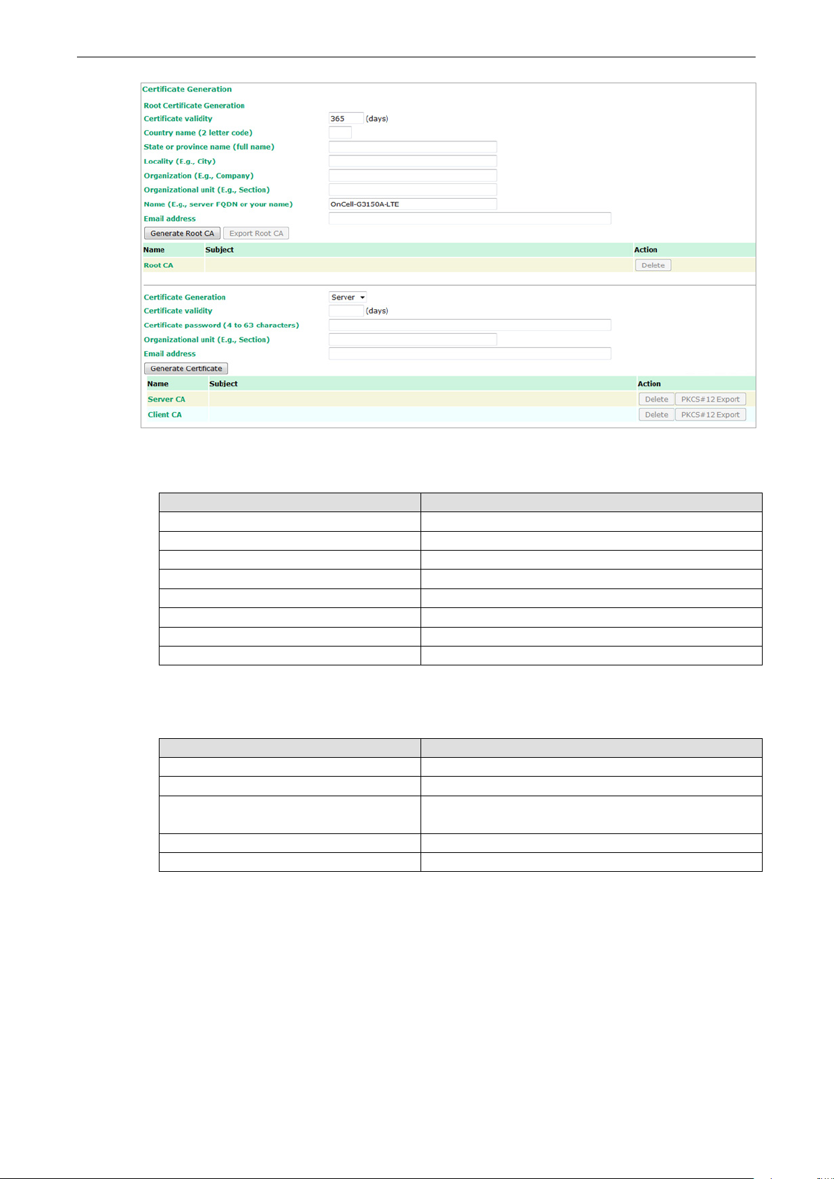
OnCell 3120-LTE-1 Web Console Configuration
3-67
To generate a root CA certificate, complete the following steps:
1. In the Certificate Generation screen, enter information in the fields under Root Certificate Generation.
Setting Description
Certificate validity Enter the number of days the certificate is valid for.
Country name(2 letter code) Enter the country.
State or province name(full name) Enter the state or the province.
Locality (E.g., city) Enter the city.
Organization(E.g., company) Enter the name of the organization.
Organizational unit(E.g., section) Enter the unit or section in the organization.
Name(E.g., server, FQDN or your name) Enter a name (such as a server name or your name).
Email address Enter an email address.
2. Click Generate Root CA.
After you have generated the root CA certificate, generate a local certificate and export the key files. In
the Certificate Generation screen, enter information in the fields under Local Certificate Settings.
Setting Description
Certificate Generation Generate a certificate for Server or Client
Certificate validity Enter the number of days the certificate is valid for.
Certificate Password (4 to 63
characters)
Organizational unit (E.g., Section) Enter the unit or section in the organization.
Email address Enter an email address.
Enter a password to create a password-protected
certificate.
Page 81

OnCell 3120-LTE-1 Web Console Configuration
3-68
schedule management functions. The power consumption
Scheduling and Power Management
The OnCell 3120-LTE-1 is able to enter 2 levels of standby mode to reduce power consumption when the
OnCell is idle. Sleep mode allows the OnCell’s CPU to enter power saving mode and effectively reduces the
power consumption to less than 2 watts. While the cellular connection is still alive, the OnCell can be woken
up from sleep by Remote SMS Control or by setting a regular schedule. Hibernate mode puts the OnCell into
deeper sleep by shutting off all active components except for a heartbeat. You can only wake the OnCell
from hibernation by using the schedule management function.
Setting Description Factory Default
Power Saving Mode
Cellular connection
fully functional time
• Disable—The OnCell device will not enter power saving
mode.
• Sleep mode—The OnCell device can enter and leave
power saving mode using the remote SMS control or
in this mode is 2 W.
Note: If you select this mode, enable Enter sleep mode
and Leave sleep mode on the Remote SMS Control
page.
• Hibernate mode—The OnCell device can enter and
leave power saving mode using the schedule
management function. The power consumption in this
mode is 40 mW.
• Hourly—Sets the minute in every hour when the OnCell
device will enter and leave the power saving mode. The
time (MM) should be set for both Enter power saving
mode time and Leave power saving mode time.
• Daily—Sets the hour/minute every day when the OnCell
device will enter and leave the power saving mode. The
time (HH:MM) should be set for both Enter power
saving mode time and Leave power saving mode
time.
• Customization—Sets the day(s) of the week and the
hour/minute of the selected day(s) when the OnCell
device will enter and leave the power saving mode. The
time (HH:MM) should be set for both Enter power
saving mode time and Leave power saving mode
Disable
Customization
Page 82

OnCell 3120-LTE-1 Web Console Configuration
3-69
ATTENTION
The serial parameters for the each
by the connected serial device. You may need to refer to your serial device’s user’s manual to determine the
appropriate serial communication parameters.
ATTENTION
The serial
by the connected serial device. You may need to refer to your serial device’s user’s manual to determine the
appropriate serial communication parameters.
Setting Description Factory Default
time. Note that only one time can be set for each day of
the week.
Serial Port Settings
Communication Parameters
Setting Description Factory Default
Port alias This optional field allows you to assign an alias to a port for
easier identification.
None
Setting Description Factory Default
Baudrate This field configures the port’s baudrate. Select one of the
standard baudrates from the dropdown box, or select Other
and then type the desired baudrate in the input box.
Setting Description Factory Default
Data bits The Packet length setting refers to the maximum amount of
parameters for the each serial port on the OnCell 3120-LTE-1 should match the parameters used
data that is allowed to accumulate in the serial port buffer
before sending. At the default of 0 for packet length, no
maximum amount is specified and data in the buffer will be
serial port on the OnCell 3120-LTE-1 should match the parameters used
115200
8
Page 83
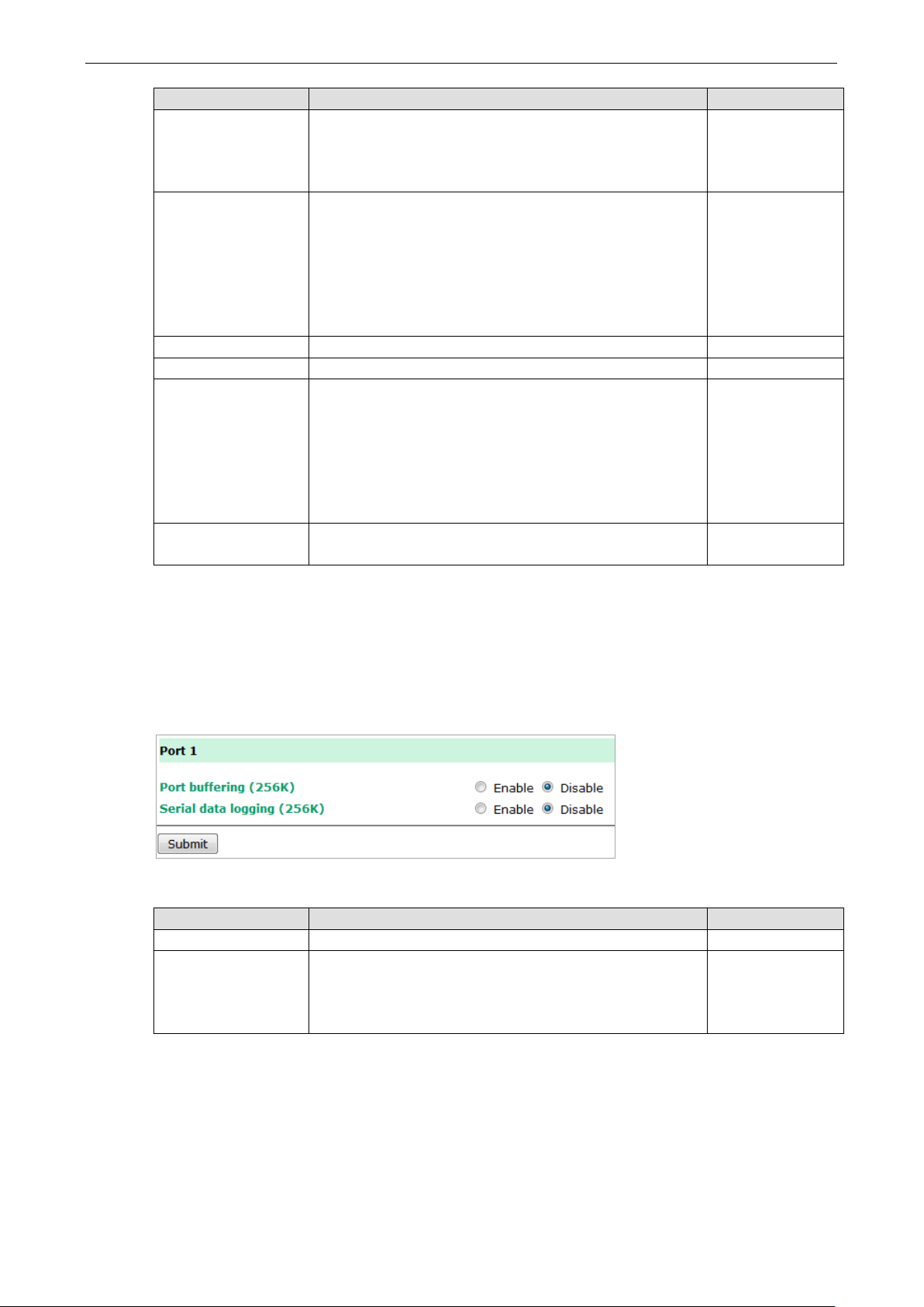
OnCell 3120-LTE-1 Web Console Configuration
3-70
specified, data in the buffer will be sent as soon it reaches the
delimiter to control when data should be
Setting Description Factory Default
sent as specified by the delimiter settings or when the buffer
is full. When a packet length between 1 and 1024 bytes is
specified length.
Stop bits When Delimiter 1 is enabled, the serial port will queue the
data in the buffer and send the data to the Cellular or
Ethernet port when a specific character, entered in hex
format, is received. A second delimiter character may be
enabled and specified in the Delimiter 2 field, so that both
characters act as the
sent.
Parity This field configures the parity parameter. None
Flow control This field configures the flow control type. RTS/CTS
FIFO This field enables or disables the 128-byte FIFO buffer. The
OnCell 3120-LTE-1 provides FIFO buffers for each serial port,
for both the Tx and Rx signals. Note, however, that you
should disable the port’s FIFO setting if the attached serial
device does not have a FIFO buffer of its own. This is because
a serial device that does not have its own buffer may not be
able to keep up with data sent from the OnCell’s FIFO buffer.
Interface You may configure the serial interface to RS-232, RS-422,
RS-485 2-wire, or RS-485 4-wire.
1
Disable
RS-232
Data Buffering/Log
The OnCell 3120-LTE-1 supports port buffering to prevent the loss of serial data when the Cellular or
Ethernet connection is down. Port buffering can be used in Real COM, Reverse Real COM, RFC2217, TCP
Server, TCP Client modes. For other modes, the port buffering settings will have no effect. The maximum
buffer up to 256K, the data over 256K will overwrite previous data buffering.
Setting Description Factory Default
Port buffering You may enable port buffering by setting this field to Enable. Disable
Serial data logging If this field is set to Yes, the OnCell 3120-LTE-1 will store
data logs on the system RAM for all serial ports. Note that
this data is not saved when the OnCell 3120-LTE-1 is
powered off.
Disable
Cipher Settings
Click Cipher Settings to set the port cipher settings for data encryption.
Page 84
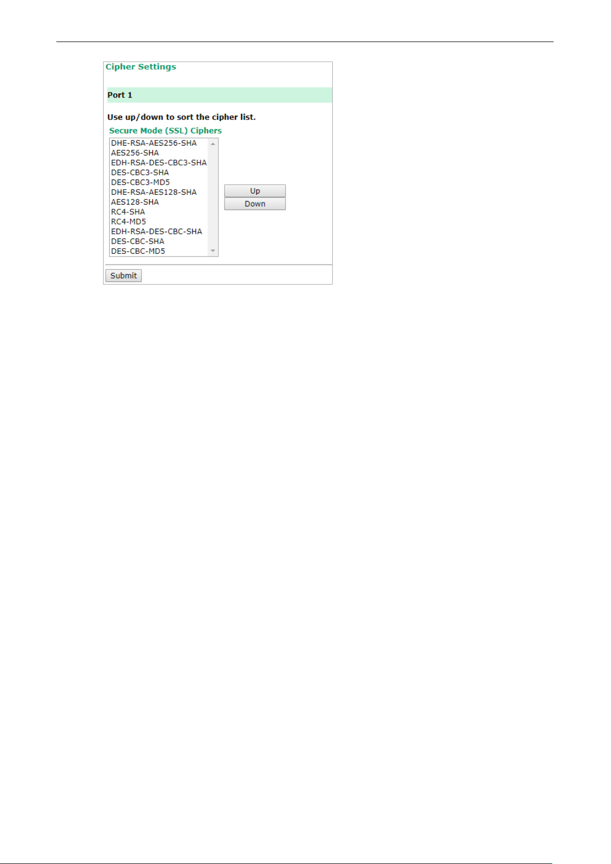
OnCell 3120-LTE-1 Web Console Configuration
3-71
Page 85

OnCell 3120-LTE-1 Web Console Configuration
3-72
Logs and Notification
Since industrial-grade devices are often located at the endpoints of a system, these devices will not always
know what is happening elsewhere on the network. This means that these devices must provide system
maintainers with real-time alarm messages. Even when system administrators are out of the control room
for an extended period, they can still be informed of the status of devices almost instantaneously when
exceptions occur.
In addition to logging these events, the OnCell 3120-LTE-1 supports different approaches to warn engineers
automatically, such as SNMP trap and email.
System Log
System Log Event Types
Detail information for grouped events is shown in the following table. You can select the Enable logging
check box to enable the selected event types. All default values are enabled (checked). The log for system
events can be seen in Logs and Notifications > System Log.
The following table describes the types of system logs:
System-related events Event is triggered when…
System restart (warm start) The OnCell 3120-LTE-1 is rebooted, such as when its settings are
changed (IP address, subnet mask, etc.).
Network-related events Event is triggered when…
LAN link on The LAN port is connected to a device or network. It takes 0.5
seconds for the system to detect and log this event.
LAN link off The port is disconnected (e.g., the cable is pulled out, or the
opposing device shuts down). It takes 0.5 seconds for the
system to detect and log this event.
Config-related events Event is triggered when…
Configuration Changed A configuration item has been changed.
Configuration file import via Web Console The configuration file is imported to the OnCell 3120-LTE-1.
Console authentication failure An incorrect password is entered.
Firmware upgraded The OnCell 3120-LTE-1’s firmware is updated.
VPN events Event is triggered when…
Power transition (On -> Off) The OnCell 3120-LTE-1 is powered down.
Power transition (Off -> On) The OnCell 3120-LTE-1 is powered.
Syslog
This function provides the event logs for the Syslog server. The function supports up to three configurable
Syslog servers and Syslog server UDP port numbers. When an event occurs, the event will be sent as a
Syslog UDP packet to the specified Syslog servers.
Page 86

OnCell 3120-LTE-1 Web Console Configuration
3-73
Syslog Event Types
Detail information for the grouped events is shown in the following table. You can the Enable log check box
to enable the selected event types. All default values are enabled (checked).
For information on the event types, refer to the System Log Event Types section.
Syslog Server Settings
You can configure the parameters for your Syslog server on the Syslog Server Settings screen.
Field Description Factory Default
Syslog server 1/2/3 Enter the IP address of the 1st/ 2nd/ 3rd Syslog Server N/A
Syslog port Enter the UDP port for the syslog server. 514
Page 87

OnCell 3120-LTE-1 Web Console Configuration
3-74
ATTENTION
Consult your Network Administrator or ISP for the proper ma
may not work properly if it is not configured correctly. The OnCell
LOGIN, PLAIN, and CRAM
Email Notifications
Notification Event Types
Select the Active checkbox to enable an event item. By default, all values are deactivated (unchecked).
For information on the event types, refer to the System Log Event Types section.
Email Server Settings
The E-mail server settings determine how e-mail warnings are sent for system and serial port events. You
may configure up to 4 e-mail addresses to receive automatic warnings.
-MD5 (RFC 2554).
il server settings. The Auto warning function
3120-LTE-1’s SMTP AUTH supports
Setting Description Factory Default
Mail server This field is for your mail server’s domain name or IP
address.
User name This field is for your mail server’s user name, if required. N/A
Password This field is for your mail server’s password, if required. N/A
N/A
Page 88

OnCell 3120-LTE-1 Web Console Configuration
3-75
From email address This is the email address from which automatic email
To email address
1 to 4
Trap
Traps can be used to signal abnormal conditions (notifications) to a management station. This trap-driven
notification can make your network more efficient.
Because a management station usually takes care of a large number of devices that have a large number of
objects, it will be overloading for the management station to poll or send requests to query every object on
every device. It would be better if the managed device agent could notify the management station by
sending a message known as a trap for the event.
Trap Event Types
Select Active to enable the event types.
For information on the event types, refer to the System Log Event Types section.
warnings will be sent.
This is the email address or addresses to which the automatic
email warnings will be sent.
N/A
N/A
SNMP Trap Receiver Settings
SNMP traps are defined in SMIv1 MIBs (SNMPv1) and SMIv2 MIBs (SNMPv2c). The two styles are basically
equivalent, and it is possible to convert between the two. You can set the parameters for SNMP trap
receivers through the web page.
Field Description Default setting
Trap version Select the SNMP version for SNMP traps. V1
Page 89

OnCell 3120-LTE-1 Web Console Configuration
3-76
Field Description Default setting
Trap server
IP/name
Trap community Enter the community string or password (up to 31 characters)
Enter the IP address or domain name of the SNMP trap server.
alert
for authentication.
SMS
SMS Event Types
Select Active to enable the event types. For information on the event types, refer to the System Log Event
Types section.
SMS Alert Settings
You can set the OnCell 3120-LTE-1 to send SMS notifications to up to four phone numbers and select a
message encoding format in the SMS Alert Settings screen.
Field Description Factory Default
To phone number
1/2/3/4
Enter the phone numbers to which the OnCell 3120-LTE-1
sends SMS notifications.
Page 90

OnCell 3120-LTE-1 Web Console Configuration
3-77
Status
Serial
Serial to Network Connections
Go to Serial to Network Connections under Serial Status to view the operation mode and status of each
connection for each serial port. All monitor functions will refresh automatically every 15 seconds.
The Real COM mode, Reverse Real COM mode and TCP server mode support up to 2 devices connection,
TCP Client mode support up to 4 devices connection.
Serial Port Status
Go to Serial Port Status under Serial Status to view the current status of each serial port. Serial Port
Status Buffering monitors port buffering usage (bytes) of the serial port. Go to Serial Port Settings >
Port 1 > Data Buffering/Log to enable Port buffering function.
A green dot indicates active, and a gray dot indicates inactive
Serial Port Error Count
Go to Serial Port Error Count under Serial Status to view the error count for each serial port.
Description
Frame Errors due to wrong Baudrate, Parity (even/odd), and Stop bit settings.
Parity Errors in parity setting (parity on / off) between both sites.
Overrun The number of times the operation-mode application overload in order to handle the data
transmission.
Break The transmission breaks originating from serial devices connected behind the OnCell
3120-LTE-1
Page 91

OnCell 3120-LTE-1 Web Console Configuration
3-78
Serial Port Settings
Go to Serial Port Settings under Serial Status to view a summary of the settings for each serial port.
Serial Data Log
Data logs for the serial port can be viewed in ASCII or HEX format. After selecting the serial port and
format, you may click Select all to select the entire log if you wish to copy and paste the contents into a
text file.
R - Receiver / T - Transmission to the serial device.
Cipher Usage Status
Page 92

OnCell 3120-LTE-1 Web Console Configuration
3-79
VPN
VPN System Log Description
The following table lists the system logs for the VPN feature. [VPN name] indicates the name of the VPN
tunnel you have created on the OnCell 3120-LTE-1.
System Log Entry Description
[VPN name] mismatch of PSK Pre-shared key mismatch.
[VPN name] Phase 1 start VPN tunnel phase 1 start.
[VPN name] Phase 1 pass VPN tunnel phase 1 pass.
[VPN name] Phase 2 start VPN tunnel phase 2 start.
[VPN name] Phase 2 pass VPN tunnel phase 2 pass.
[VPN name] received Delete ISAKMP SA Remote VPN tunnel request to delete ISAKMP SA.
[VPN name] no Preshared Key Found No pre-shared key is found.
[VPN name] policy doesn't allow PRESHARED KEY The encryption algorithm does not allow pre-shared
key.
[VPN name] policy doesn't allow RSASIG VPN encrypt algorithm does not allow RSA or X.509.
[VPN name] DPD timeout - declaring peer dead No response from a peer. PDP timeout.
[VPN name] DPD: Hold connection Clear the remote VPN SA and keep the peer routing
table status.
[VPN name] DPD: Clearing Connection Clear the remote VPN SA and peer routing table
status.
[VPN name] DPD: Restarting Connection Renegotiate VPN SA immediately.
[VPN name] encrypt alg is different VPN encryption mismatch.
[VPN name] hash alg is different VPN hash mismatch.
[VPN name] DH group is different VPN Diffie-Hellman group mismatch.
[VPN name] Ignore initial Aggr message Ignore aggressive requests from a remote VPN
gateway.
[VPN name] Maybe ID format error Invalid local or remote VPN ID format.
[VPN name] we require peer ID differ from peer
declares ID
[VPN name] no suitable connection for peer No corresponding VPN connection for a remote peer
[VPN name] connect_fail_log:ip_port Fail to route VPN connection to [IP address].
[VPN name] send payload name Send “VPN INVALID_KEY_INFORMATION,
[VPN name] receive payload name Receive “VPN INVALID_KEY_INFORMATION,
Remote ID mismatch.
from the VPN responder.
INVALID_CERTIFICATE or….” to a remote VPN
gateway.
INVALID_CERTIFICATE, or “…” from a remote VPN
gateway.
IPsec Logs
The IPsec triggered events are recorded in IPsec Logs. You can export the log contents to an available
viewer by clicking Export Log. You can use the Clear Log button to clear the log contents and the Refresh
button to refresh the log.
Page 93
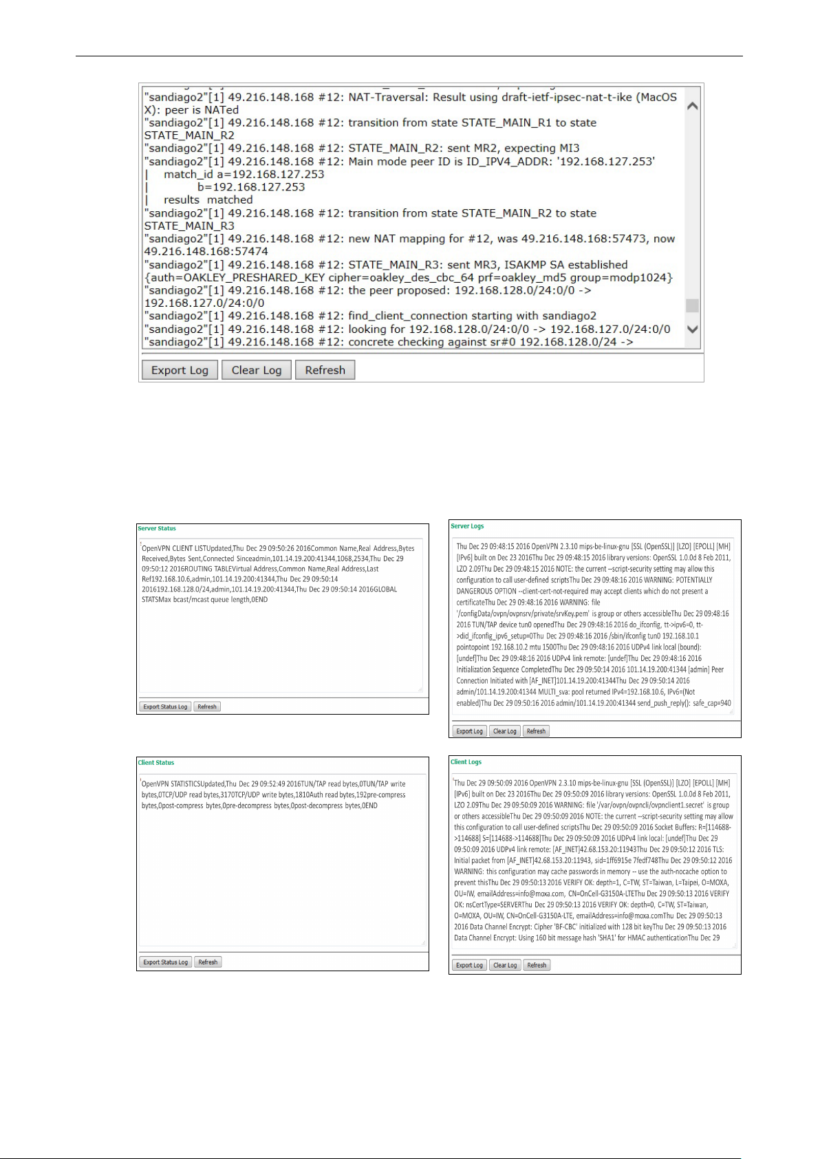
OnCell 3120-LTE-1 Web Console Configuration
3-80
OpenVPN Status and Logs
The OpenVPN triggered events at Server and Clients are recorded in each Status and Logs.
You can export the log contents to an available viewer by clicking Export Log. You can use the Clear Log
button to clear the log contents and the Refresh button to refresh the log.
Page 94

OnCell 3120-LTE-1 Web Console Configuration
3-81
NOTE
•
• Status: You can view OpenVPN connection status such as OpenVPN is connected, disconnected and
initiating connection and information on the client’s access to the server in the server logs.
Logs: The Logs show more detailed information than the Status and provide engineers with information
for review and trouble shooting. Additional information includes negotiation process, key exchange, and
error recordings.
DNS Status
The DNS Status screen displays the DNS server to which the OnCell 3120-LTE-1 is connected and the DNS
server information.
Go to DNS Status for DNS server settings information designated at General Setup > Network Settings.
It shows OnCell 3120-LTE-1’s DNS assigned by DNS server and Server 3/4 is stand for Primary DNS and
Secondary DNS information at General Setup > Network Settings
SIM Status
The SIM Status screen displays the current SIM card in use and the status of the SIM cards installed in the
OnCell 3120-LTE-1.
DHCP Client List
The DHCP Client List shows all the clients that require and have successfully received IP assignments. You
can click the Refresh button to refresh the list.
Page 95

OnCell 3120-LTE-1 Web Console Configuration
3-82
You can press Select all button to select all content in the list for further editing.
System Log
Triggered events are recorded in System Log. You can export the log contents to an available viewer by
clicking Export Log. You can use the Clear Log button to clear the log contents and the Refresh button to
refresh the log.
LAN Status
The LAN Status screen displays the LAN port information of the device.
System Status
The System Status screen displays the OnCell 3120-LTE-1 internal memory capacity status and CPU load
information.
Page 96

OnCell 3120-LTE-1 Web Console Configuration
3-83
The total number of input IP datagram packets that the device received from all
Network Status
Network Statistics
The Network Statistics screen displays information on the network interfaces of the device and protocols
used along with the packets received and transmitted.
The network statistic parameters and values are described in the following tables:
Interface Action Description
LAN Received The number of packets the device received through the LAN interface
Sent The number of packets the device sent through the LAN interface
CWAN Received The number of packets the device received through the CWAN interface
Sent The number of packets the device sent through the CWAN interface
Protocol Actions Description
IP Received
interfaces
Sent The total number of output IP datagram packets that the device sent from all
interfaces
RDiscard The input IP datagram packets discarded for various reasons (e.g.: Lack of
buffer space)
SDiscard The output IP datagram packets discarded for various reasons (e.g.: Lack of
buffer space)
ErrAddr The input IP datagram packets received with invalid IP addresses
Errproto The input IP datagram packets received with incorrect protocol. (i.e., a protocol
other than TCP, UDP, and ICMP)
Page 97

OnCell 3120-LTE-1 Web Console Configuration
3-84
Protocol Actions Description
ErrHeader The input IP datagram packets received with invalid headers. e.g., bad
checksum, version number mismatch, and time-to-live period exceeded)
SNoRoute The input IP datagram packets received with incorrect routes
ICMP Received The total number of ICMP messages that the device received
Sent The total number of ICMP messages that the device sent
REchoReq The ICMP request packets that the device received. (e.g., Ping requests
received)
REchoRply The ICMP reply packets that the device received. (e.g., Ping replies received)
SEchoReq The ICMP request packets that the device sent. (e.g., Ping requests sent)
SEchoRply The ICMP reply packets that the device received. (e.g., Ping replies received )
UDP Received The total number of input UDP datagram packets received by the device
Sent The total number of output UDP datagram packets received by the device
ErrHeader The input UDP datagram packets received with invalid headers
ErrPorts The input UDP datagram packets received with incorrect port numbers
Protocol Actions Description
TCP Received The total number of input TCP segment packets received by the device
Sent The total number of output TCP segment packets received by the device
ErrHeader The input TCP segment packets received with invalid headers. (e.g., bad
checksum)
ErrPorts The input TCP segment packets received with the wrong port number
ReSent The output TCP segment packets retransmitted
CurrEstab The number of TCP connections established (e.g. status is ESTABLISHED or
CLOSE-WAIT)
Opens The number of TCP connections to be opened (e.g. status is SYNC-sent,
SYNCRCBD, SYNC_RCVD)
ARP Table
The ARP table is for maintenance people to ping the destination device and get the destination MAC address
so as to clarify the connection issue.
LLDP
The LLDP displays the information of the device that connected to OnCell 3120-LTE-1.
Field Description Default setting
Interface The device physical internet interface, such as Wi-Fi, Cellular
and Ethernet port.
System Name A user-defined device system name. System Name
ID A user-defined device ID. ID
IP The device IP address IP
Port The open port that connect at device to OnCell 3120-LTE-1 Port
Interface
Page 98

OnCell 3120-LTE-1 Web Console Configuration
3-85
Possible flags include:
U: route is up
D: route is down
G: use gateway
+: default gateway
T: static route
H: target is a host
Field Description Default setting
Port Description The open port description that user given. Port Description
Routing Table
The Routing Table screen displays the list of routes the OnCell 3120-LTE-1 uses to send packets on each
interface.
Page 99
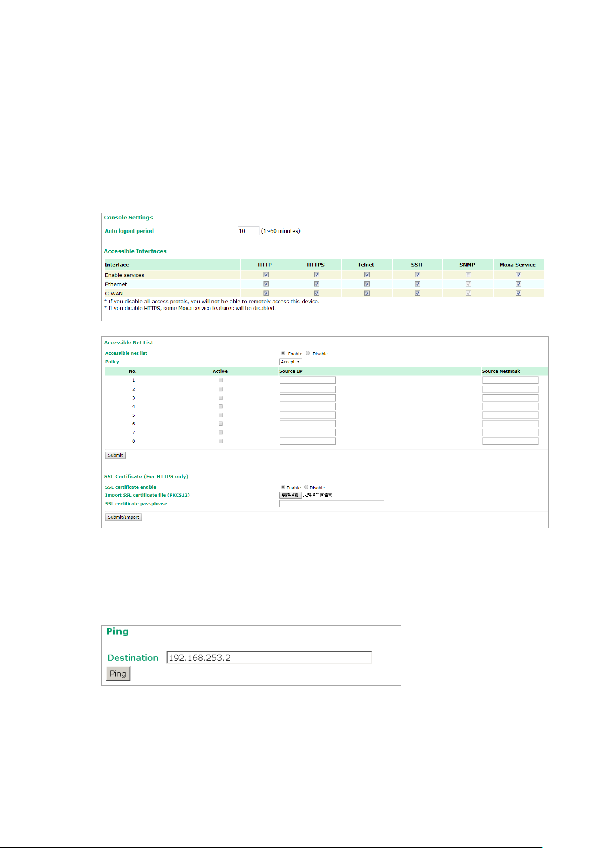
OnCell 3120-LTE-1 Web Console Configuration
3-86
Maintenance
Maintenance functions provide the administrator with tools to manage the OnCell 3120-LTE-1 and
wired/wireless networks.
Console Settings
You can enable or disable access permissions to the device and Moxa Service such as MXstudio and Wireless
Search Utility. For greater security, we recommend only allowing access to the two secure consoles, HTTPS
and SSH.
Ping Command
Ping helps to diagnose the integrity of wired or wireless networks. By inputting a node’s IP address in the
Destination field, you can use the ping command to make sure it exists and whether or not the access
path is available.
If the node and access path are available, you will see that all packets were successfully transmitted with no
loss. Otherwise, some, or even all, packets may get lost, as shown in the following figure.
Page 100

OnCell 3120-LTE-1 Web Console Configuration
3-87
ATTENTION
Please make sure the power source is stable when you
disruption
Firmware Upgrade
The OnCell 3120-LTE-1 can be enhanced with more value-added functions by installing firmware upgrades.
The latest firmware is available at Moxa’s download center.
Before running a firmware upgrade, make sure the OnCell 3120-LTE-1 is off-line. Click the Browse button
to specify the firmware image file and click Firmware Upgrade and Restart to start the firmware
upgrade. After the progress bar reaches 100%, the OnCell 3120-LTE-1 will reboot itself.
When upgrading your firmware, the OnCell 3120-LTE-1’s other functions will not be accessible.
may damage your OnCell 3120-LTE-1.
Configuration Import & Export
You can use the Config Import Export screen to back up or restore the following:
• Configuration settings on the OnCell 3120-LTE-1
• ABC-02 configuration
• MIB
In the Config Import section, click Choose File to select a configuration file and click Config Import
button to begin importing configuration. The password is up to 31 characters.
upgrade your firmware. An unexpected power
To save the configuration file to a storage media, click Config Export. The configuration file is a text file
and you can view and edit it with a general text-editing tool.
For MIBs, click MIB Export to save the MIB file to a storage media. The configuration file is a .my file and
you can import using a general SNMP tool and use to remotely control or configure the OnCell 3120-LTE-1.
 Loading...