

Page 1

P/N: 1802056001016
Technical Support Contact Information
www.moxa.com/support
2021 Moxa Inc. All right s reserved.
NPort 5600-8-DT Series
Quick Installation Guide
Version 5.1, January 2021
*1802056001016*
Page 2

Overview
NOTE
The operating temperature of the power adapter in the box is
from 0 to 40°C. If your application is out of this range, please use
a power adapter supplied by UL Listed External Power Supply
(The power output meets SELV and LPS and rated 12 - 48 VDC,
minimum current 0.73 A).
The NPort 5600-8-DT Series includes the following models:
• NPort 5610-8-DT: 8 ports, RS-232, DB9
• NPort 5610-8-DT-T: 8 ports, RS-232, DB9, -40 to 75°C operating
temperature
• NPort 5610-8-DT-J: 8 ports, RS-232, RJ45
• NPort 5650-8-DT: 8 ports, RS-232/422/485, DB9
• NPort 5650-8-DT-T: 8 ports, RS-232/422/485, DB9, -40 to 75°C
operating temperature
• NPort 5650-8-DT-J: 8 ports, RS-232/422/485, RJ45
• NPort 5650I-8-DT: 8 ports, RS-232/422/485, DB9, optical isolation
• NPort 5650I-8-DT-T: 8 ports, RS-232/422/485, DB9, optical isolation,
-40 to 75°C operating temperature
Package Checklist
The NPort 5600-8-DT package should contain the following items:
• 1 x NPort 5600-8-DT 8-port serial device server
• 1 x 100 to 240 VAC power adapter (excluding –T models)
• 1 x power cord
• 1 x Ethernet cable: CBL-RJ458P-100
• 1 x wall-mount kit
• Quick installation guide
• Warranty card
Optional Accessories:
• DK-35A: DIN rail mounting kit (35 mm)
• CBL-RJ45M9-150: 8-pin RJ45 to male DB9 ca ble, 150 cm
• CBL-RJ45F9-150: 8-pin RJ45 to female DB9 cable, 150 cm
• CBL-RJ45M25-150: 8-pin RJ45 to male DB25 cable, 150 cm
• CBL-RJ45F25-150: 8-pin RJ45 to female DB25 cable, 150 cm
• NP21101: DB25-M to DB9-F RS-232 cable, 30 cm
Please notify your sales representative if any of the above items are
missing or damaged.
- 2 -
Page 3
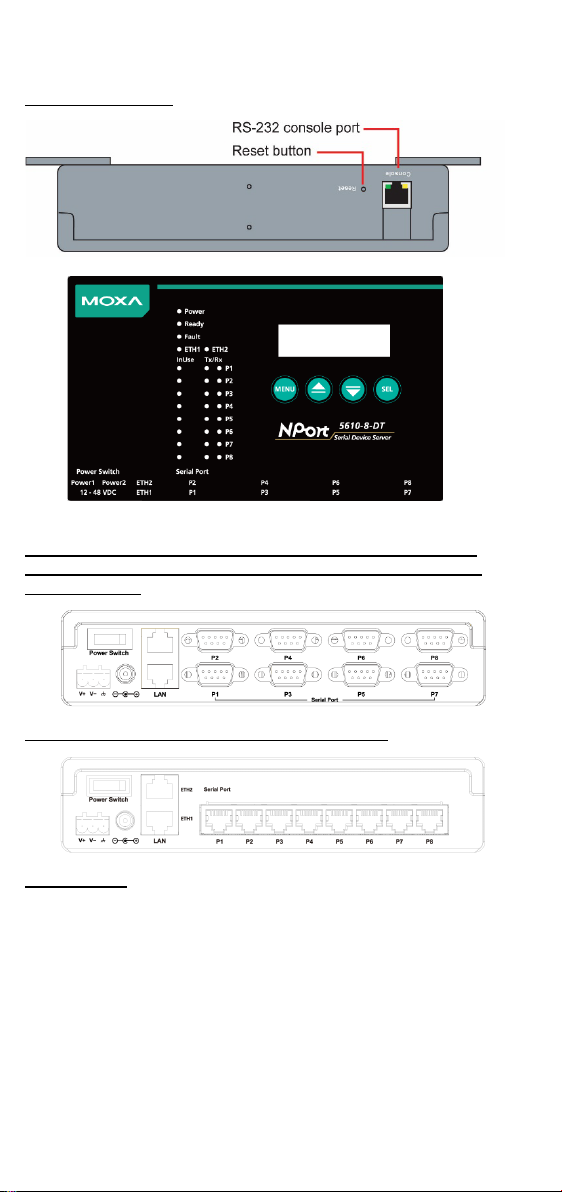
Hardware Introduction
Top and Rear View
Front View (NPort 5610-8-DT, NPort 5610-8-DT-T, NPort
5650-8-DT, NPort 5650-8-DT-T, NPort 5650I-8-DT, NPort
5650I-8-DT-T)
Front View (NPort 5610-8-DT-J, 5650-8-DT-J)
Reset Button
The reset button is used to load the factory defaults. Use a pointed object
to hold the reset button down for five seconds. You may release the reset
button when the Ready LED stops blinking.
- 3 -
Page 4

LED Indicators
Name
Color
Function
Red
Power is on.
Off
Power is off.
Steady:
NPort is operational
Blinkin g:
NPort is responding to NPort
Administrator “Locate” function
Off
Power is off or fault condition exists.
IP conflict or DHCP or BOOTP server did not
respond properly.
Off
No fault condition detected.
being transmitted.
Blinkin g:
Network is connected, data is
being transmitted.
Ethernet cable is disconnected or has a
short.
being transmitted.
Blinkin g:
Network is connected, data is
being transmitted.
Ethernet cable is disconnected or has a
short.
Serial port has been opened by server side
software.
Serial port is not currently opened by server
side software.
Green (Tx)
Serial device is transmitting data.
Orange (Rx)
Serial device is receiving data.
Off
No data is flowing to or from the serial port.
The LED indicators on the top panel are used to display status as follows:
PWR
Ready
Fault
ETH1
ETH2
InUse
(P1 to P8)
Tx/Rx
(P1 to P8)
Green
Red
Steady: Network is connected, no data is
Green
Off
Steady: Network is connected, no data is
Green
Off
Green
Off
Hardware Installation
STEP 1: After removing the NPort 5600-8-DT from the box, place it on a
desktop or other horizontal surface. Connect the 12-48 VDC power
adaptor to the NPort 5600-8-DT’s power input when using an AC power
source, or connect the NPort 5600-8-DT’s terminal block directly to a DC
power source.
STEP 2: Use an Ethernet cable to connect the NPort 5600-8-DT to a
network hub or switch. You can also connect directly to your computer’s
Ethernet port, which is convenient for in itial configuration or testing.
STEP 3: Connect the NPort 5600-8-DT’s serial port to a serial device.
Wall or Cabinet Mounting
The NPort 5600-8-DT comes with two metal attachment plates to allow
installation on a wall or the inside of a cabinet. First, attach the brackets
to the back of the NPort with screws. Next, mount the unit on a wall or
cabinet with screws.
- 4 -
Page 5

Screws should be less than 6.0 mm in head diameter, and less than 3.5
Standard Attachment
DK-35A Attachment
1 2 3 Pull High
Pull Low
Terminator
ON
1KΩ
1KΩ
120Ω
Default
OFF
150KΩ
150KΩ
–
NOTE
For security-related configuration, please refer to the manual’s
Cybersecurity Considerations chapter.
mm in shaft diameter.
DIN Rail Mounting
DIN-rail attachments can be purchased separately to attach the product
to a DIN-rail. The DIN-rail attachments should be oriented with the metal
springs on top.
Pull High/Low Resistors for RS-485
Use the set of DIP switches on the bottom panel to set the pull high/low
resistor values for each serial port. To acce ss the switches, remove the
screws holding the DIP switch cover in place and flip open the cover.
There are three DIP switches for each port’s pull high/low resistors:
SW
Software Installation Information
For the NPort’s configuration, the default IP address of the NPort is: LAN:
Static IP = 192.168.127.254; netmask = 255.255.255.0
You may log in with the username admin and password moxa to change
any settings to meet your network topology (e.g., IP address) or serial
device (e.g., serial parameters). If you would like to apply Real COM
mode to your application, you will need to install the NPort’s driver on
your desktop. You may also refer to Moxa’s support website
https://www.moxa.com/support/ for user’s manual, driver, Device
Search Utility, and so on.
- 5 -
Page 6

NOTE
For the NPort with DB Male serial ports, you may refer to the DB9
Male Ports pin assignment section to loop back pin 2 and p in 3 for
the RS-232 interface to carry out a self test on the device.
RS-422
4-wire RS-485
2-wire
RS-485
1
DSR – – 2 RTS
TxD+
– 3 GND
GND
GND
4
TxD
TxD-
– 5 RxD
RxD+
Data+
6
DCD
RxD-
Data-
7
CTS – – 8 DTR – –
NOTE
The NPort 5610-8-DT-J supports RS-232 only.
RS-422
4-wire RS-485
2-wire
RS-485
1
DCD
TxD-(A)
– 2 RxD
TxD+(B)
– 3 TxD
RxD+(B)
Data+(B)
4
DTR
RxD-(A)
Data-(A)
5
GND
GND
GND
6
DSR – – 7 RTS – – 8 CTS – – 9 – – –
NOTE
The NPort 5610-8-DT supports RS-232 only.
Serial
RJ45
DB9(F)
DB9(M)
DB25(M)
DB25(F)
DSR 1 6 4 6 20
DTR
RTS 2 7 8 4 5
CTS
GND 3 5 5 7 7
GND
TxD 4 3 2 2 3
RxD
RxD 5 2 3 3 2
TxD
DCD 6 1 1 8 8
DCD
CTS 7 8 7 5 4
RTS
DTR 8 4 6
20
6
DSR
Pin Assignments and Cable Wiring
RJ45 Ports (NPort 5610-8-DT-J, 5650-8-DT-J)
Pin RS-232
DB9 Male Ports (NPort 5610-8-DT, 5650-8-DT, 5650I-8-DT)
Pin RS-232
RS-232 Cables
NPort
- 6 -
Device
Page 7

RS-422, 4-wire RS-485 Cables
Serial
RJ45
DB9(F)
DB9(M)
DB25(M)
DB25(F)
TxD+ 2 2 3 3 2
RxD+
GND 3 5 5 7 7
GND
TxD- 4 1 1 8 8
RxD-
RxD+ 5 3 2 2 3
TxD+
RxD- 6 4 6
20
6
TxD-
Serial
RJ45
DB9(F)
DB9(M)
DB25(M)
DB25(F)
GND 3 5 5 7 7
GND
Data+ 5 3 2 2 3
Data+
Data- 6 4 6
20
6
Data-
Power Requirements
611 mA @ 12 VDC, 300 mA @ 24 VDC, 140 mA
611 mA @ 12 VDC, 300
615 mA @ 12 VDC, 300 mA @ 24 VDC, 156 mA
615 mA @ 12 VDC, 300
mA @ 48V
Certifications
Regulatory Approvals
FCC Class A, CE Class A, UL, CUL, LVD
NPort
2-wire RS-485 Cables
NPort
Specifications
Input Voltage 12 to 48 VDC
NPort 5610-8-DT/NPort 5610-8-DT-T:
@ 48V
NPort 5610-8-DT-J:
mA @ 24 VDC, 140 mA @ 48V
NPort 5650-8-DT/NPort 5650-8-DT-T:
Device
Device
@ 48V
NPort 5650-8-DT-J:
mA @ 24 VDC, 156 mA @ 48V
NPort 5650I-8-DT/NPort 5650I-8-DT-T:
1,066 mA @ 12 VDC, 510 mA @ 24 VDC, 200
- 7 -
 Loading...