

Page 1

P/N: 1802021200011
Technical Support Contact Information
www.moxa.com/support
Moxa Americas:
Toll
Tel:
Fax:
Moxa China (Shanghai office):
Toll
Tel:
Fax:
Moxa Europe:
Tel:
Fax:
Moxa Asia-Pacific:
Tel:
Fax:
Moxa India:
Tel:
Fax:
2018 Moxa Inc. All rights reserved.
MPC-2120 Series
Quick Installation Guide
Edition 2.0, October 2018
-free: 1-888-669-2872
1-714-528-6777
1-714-528-6778
+49-89-3 70 03 99-0
+49-89-3 70 03 99-99
+91-80-4172-9088
+91-80-4132-1045
-free: 800-820-5036
+86-21-5258-9955
+86-21-5258-5505
+886-2-8919-1230
+886-2-8919-1231
*1802021200011*
Page 2
Overview
The MPC-2120 12-inch panel computers with Intel® Atom™ E3800 Series
processors deliver a reliable and durable platform of wide versatility for
use in industrial environments. With two software selectable
RS-232/422/485 serial ports and two gigabit Ethernet LAN ports, the
MPC-2120 panel computers support a wide variety of serial interfaces as
well as high-speed IT communications, all with native network
redundancy.
Package Checklist
Before installing the MPC-2120, verify that the package contains the
following items:
• 1 MPC-2120 panel computer
• 1 2-pin terminal block for DC power input
• 1 10-pin terminal block for DIO
• 1 2-pin terminal block for remote power switch
• 8 panel mounting screws
• Quick installation guide (printed)
• Warranty card
NOTE: Please notify your sales representative if any of the above items
are missing or damaged.
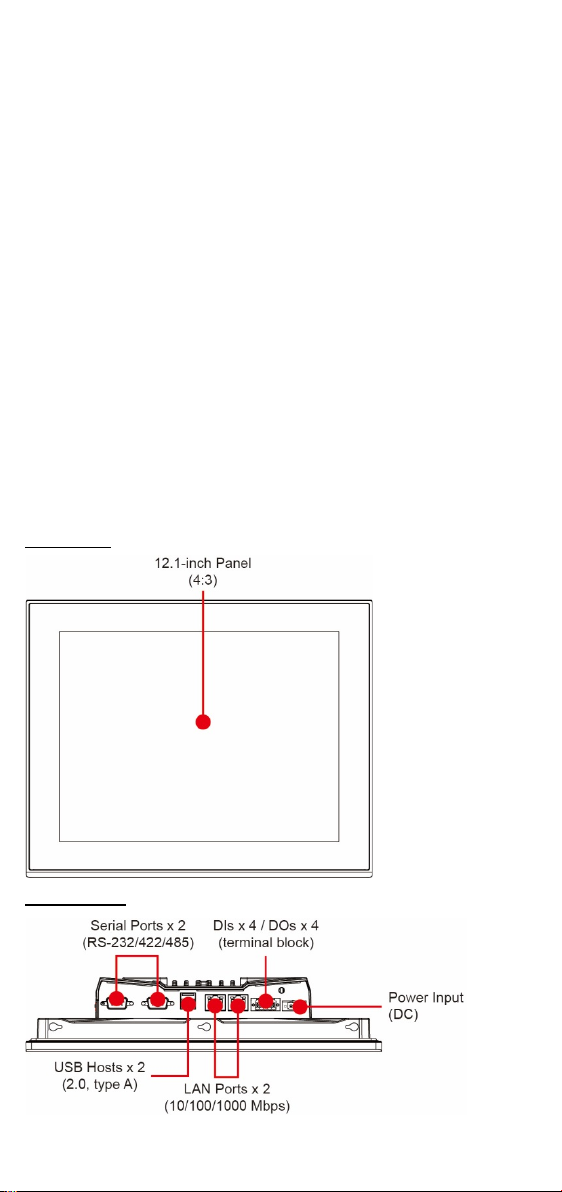
Hardware Installation
Front View
Bottom View
- 2 -
Page 3
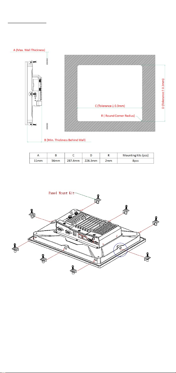
Panel Mounting
A panel-mounting kit consisting of 8 mounting units is provided in the
MPC-2120 package. For details on the dimensions and the cabinet space
required to panel mount the MPC-2120, refer to the following illustration:
To install the panel-mounting kit on the MPC-2120, place the mounting
units in the holes provided on the rear panel and push the units to the left
as shown in the illustration below:
- 3 -
Page 4
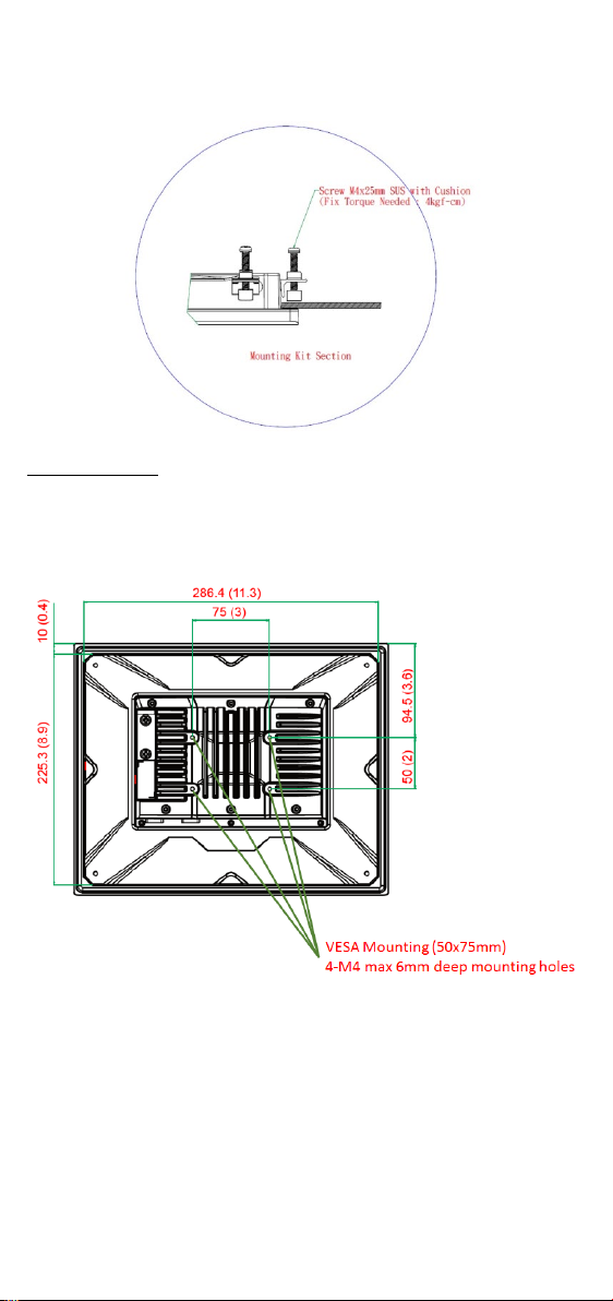
Use a torque of 4Kgf-cm to secure the mounting screws to fasten the
panel-mounting kit onto the wall.
VESA Mounting
The MPC-2120 is provided with VESA-mounting holes on the back panel,
which you can use directly without the need for an adapter. The
dimension of the VESA mounting area is 50 mm x 75 mm. You will require
four 6-mm M4 screws to VESA mount the MPC-2120.
- 4 -
Page 5
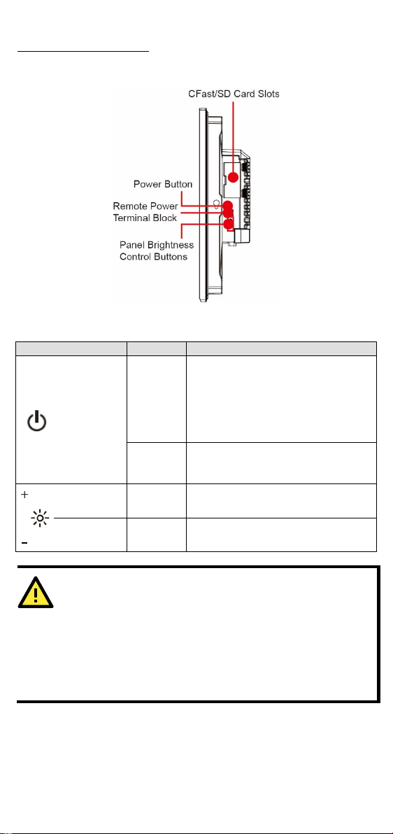
Display-Control Buttons
Symbol and Name
Usage
Function
• Power on
NOTE: You can change the function of
menu
Press and
seconds
ATTENTION
The
level of which is adjustable up to level 10. The display is
optimized for use in the
However, if you are operating the
temperature of 60°C or higher, we recommend setting the
brightness
extend the
lifetime of the display.
The MPC-2120 is provided with two display-control buttons on the right
panel.
The display-control buttons can be used as described in the following
table:
• Enter Sleep or Hibernation mode
Press
Power
• Wake up
the power button in the OS settings
hold for 4
Brightness + Press
Brightness - Press
Power off
Manually increase the brightness of
the panel
Manually decrease the brightness of
the panel
MPC-2120 comes with a 1000-nit display, the brightness
-40 to 70°C temperature range.
level of the displa y to 8 or lower in order to
- 5 -
MPC-2120 at an ambient
Page 6
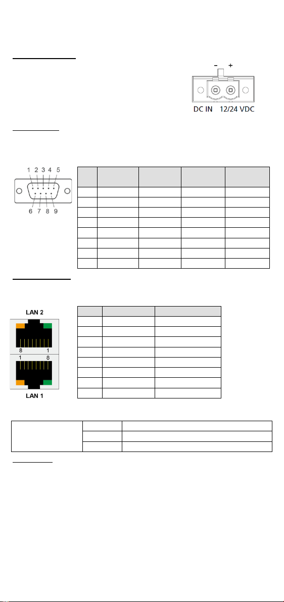
Connector Description
The
connect the power source
pin terminal
block
termina l
is
available in the
pin assignments are as shown in the figure.
RS-485
(4-wire)
RS-485
(2-wire)
1
DCD
TxDA(-)
TxDA(-)
– 2 RxD
TxDB(+)
TxDB(+)
– 3 TxD
RxDB(+)
RxDB(+)
DataB(+)
4
DTR
RxDA(-)
RxDA(-)
DataA(-)
5
GND
GND
GND
GND 6 DSR – – – 7
RTS – – – 8
CTS – –
–
Pin
100 Mbps
1000 Mbps
1
ETx+
TRD(0)+
2
ETx-
TRD(0)-
3
ERx+
TRD(1)+
4 – TRD(2)+
5 – TRD(2)-
6
ERx-
TRD(1)-
7 – TRD(3)+
8 – TRD(3)-
Green
100 Mbps Ethernet mode
Yellow
1000 Mbps (Gigabit) Ethernet mode
Off
No activity / 10 Mbps Ethernet mode
DC Power Input
MPC-2120 uses a DC power input. To
, use a 60 W power adapter. The
-block connector for the power input
accessories package. The DC
Serial Ports
The MPC-2120 offers two software-selectable RS-232/422/485 serial
ports over a DB9 connector. The pin assignments for the ports are shown
in the table below:
Ethernet Ports
The pin assignments for the two Fast Ethernet 100/1000 Mbps RJ45 ports
are sho wn in the following table:
to the 2-
Pin RS-232 RS-422
The LEDs on the LAN ports indicate the following:
LAN 1/LAN 2
(indicators on the
connectors)
USB Ports
Two USB 2.0 ports are available on the bottom panel. Use these ports to
connect mass-storage drives and other peripherals.
- 6 -
Page 7
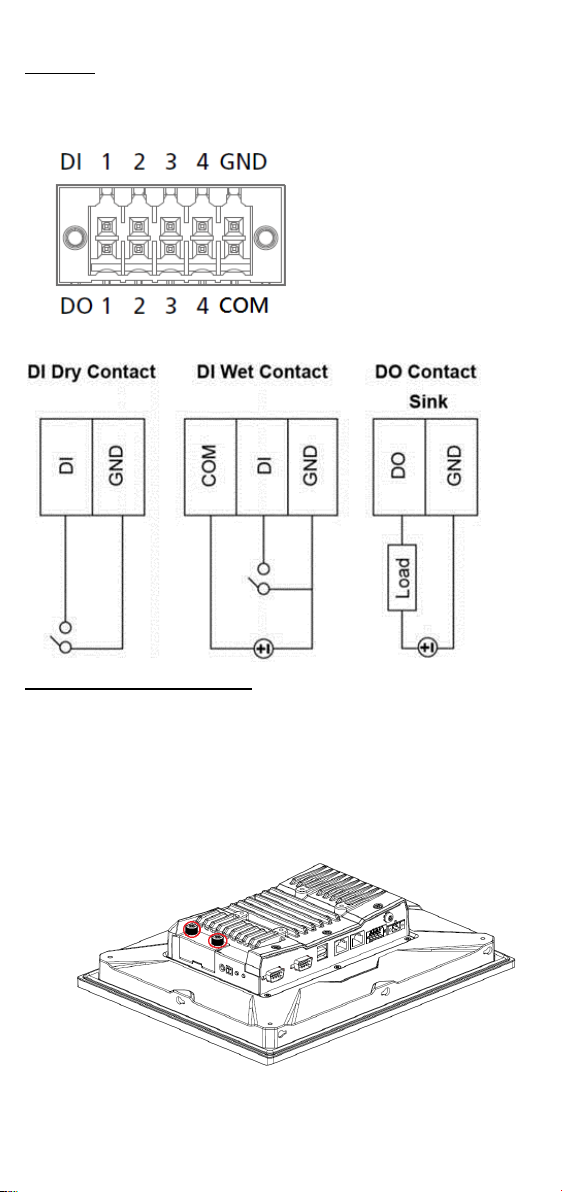
DIO Port
The MPC-2120 is provided with a DIO port, which is a 10-pin termin al
block that includes 4 DIs and 4 DOs as illustrated in the following
diagram.
Installing a CFast or SD Card
MPC-2120 provides two storage options—CFast and SD card. The storage
slots are located on the left panel. You can install the OS on the CFast card
and save your data into the SD card. For a list of compatible CFast models,
check the MPC-2120 component compatibility report available on Moxa’s
website.
To install the storage devices, do the following:
1. Remove the 2 screws holding the storage-slot cover to the MPC-2120.
- 7 -
Page 8

2. Insert the CFast or SD card into the slot using the push-push
ATTENTION
There is a risk of explos ion if the clock’s lithium batter y is
replaced with an incompatible battery.
mechanism.
3. Reattach the cover and secure it with screws.
Real-Time Clock
The real-time clock (RTC) is powered by a lithium battery. We strongly
recommend that you do not replace the lithium battery without help from
a qualified Moxa support engineer. If you need to change the battery,
contact the Moxa RMA service team. The contact details are available at:
http://www.moxa.com/rma/about_rma.aspx
.
Powering On/Off the MPC-2120
Connect a Terminal Block to Power Jack Converter to the MPC-2120
terminal block and connect a 60 W power adapter to the converter.
Supply power through the power adapter. After you have connected a
power source, the system power turns on automatically. It takes about 10
to 30 seconds for the system to boot up. You can change the power-on
behavior of your computer by changing the BIOS settings.
To power off the MPC-2120, we recommend using the "shut down"
function provided by the OS installed on the MPC. If you use the Power
button, you may enter one of the following states depending on the power
management settings in the OS: standby, hibernation, or system
shutdown mode. If you encounter problems, you can press and hold the
Power button for 4 seconds to force a hard shutdown of the system.
- 8 -
Page 9

Grounding the MPC-2120
0 to 9, A to Z, dash, blank, (,), or any character
for marketing purpose.
,
,
3.5 A or 24 VDC, 1.75 A or 12 VDC, 3.5 A
S/N
ATEX information:
Rated Cable Temp ≥ 107 °C
Proper grounding and wire routing help to limit the effects of noise from
electromagnetic interference (EMI). Run the ground connection from the
ground screw to the grounding surface prior to connecting the power
source.
Label Drawing Information
Trade Mark:
Model: Nomenclature for models MPC-2070 and
MPC-2120 series:
MPC-2070 -xx -yyyyyyyyyy
I II III
I – Screen size:
MPC-2070: 7” panel
MPC-2120: 12” panel
II – CPU type
E2: Intel® Atom™ Processor E3826 1.46 GHz
E4: Intel® Atom™ Processor E3845 1.91 GHz
(MPC-2120 series only)
III – Marketing purpose
Rating: For model MPC-2070-E2-yyyyyyyyy 12-24 VDC
2.5 A or 24 VDC, 1.25 A or 12 VDC, 2.5 A
For model MPC-2120-xx-yyyyyyyyy 12-24 VDC
II 3 G
DEMKO 18 ATEX 2048X
Ex nA IIC T4 Gc
Ambient Range :
-40 ° C ≤ Ta ≤ +7 0 °C , or -40°C ≤ Tamb ≤ +70°C
- 9 -
Page 10

IECEx Certificate no.:
IECEx UL 18.0064X
Address of
manufacturer:
Dist., New Taipei City, Taiwan
FI.4, No.135, Lane 235, Baoqiao Rd. Xindian
Condition of Use
• Subject devices are intended for use in an area of not more than
pollution degree 2 in accordance with IEC/EN 60664-1.
• Subject devices are intended for use in low risk of mechanical impact
environments.
• The equipment shall be installed (panel mount) to an enclosure that
provides a degree of protection not less than IP54 in accordance with
IEC/EN 60079-15, and accessible only by use of a tool.
Hazardous Location Standard
• EN 60079-0:2012 + A11:2013
• EN 60079-15: 2010
• IEC 60079-0 6
• IEC 60079-15 4
th
Edition
th
Edition
- 10 -
 Loading...