


P/N: 1802011310015
Technical Support Contact Information
www.moxa.com/support
Moxa Americas:
Toll
Tel:
Fax:
Moxa China (Shanghai office):
Toll
Tel:
Fax:
Moxa Europe:
Tel:
Fax:
Moxa Asia-Pacific:
Tel:
Fax:
Moxa India:
Tel:
Fax:
2017 Moxa Inc. All rights reserved.
AWK-1131A
Quick Installation Guide
Moxa AirWorks
Edition 7.0, April 2017
-free: 1-888-669-2872
1-714-528-6777
1-714-528-6778
+49-89-3 70 03 99-0
+49-89-3 70 03 99-99
+91-80-4172-9088
+91-80-4132-1045
-free: 800-820-5036
+86-21-5258-9955
+86-21-5258-5505
+886-2-8919-1230
+886-2-8919-1231
*1802011310015*

Table of Contents
Overview ............................................................................... - 3 -
Hardware Setup .................................................................... - 3 -
Package Checklist .............................................................. - 3 -
Panel Layout of the AWK-1131A .......................................... - 4 -
Mounting Dimensions ......................................................... - 5 -
DIN-Rail Mounting ............................................................. - 5 -
Wall Mounting (optional) .................................................... - 6 -
Wiring Requirements ......................................................... - 7 -
Grounding the Moxa AWK-1131A ......................................... - 7 -
Installations with Cable Extended Antennas for Outdoor
Applications ................................................................ - 8 -
Wiring the Redundant Power Inputs ..................................... - 8 -
Communication Connections ............................................... - 9 -
10/100BaseT(X) Ethernet Port Connection ....................... - 9 -
1000BaseT Ethernet Port Connection .............................. - 9 -
RS-232 Connection ...................................................... - 9 -
LED Indicators ................................................................ - 10 -
Specifications ................................................................. - 11 -
Software Setup ................................................................... - 15 -
How to Access the AWK .................................................... - 15 -
First-Time Quick Configuration .......................................... - 15 -
Point-to-Multipoint Scenario (AP/Client Mode) ................ - 16 -
Point-to-Point Scenario (Master/slave mode) .................. - 18 -
- 2 -

Overview
The AWK-1131A industrial wireless access point meets the growing need
for faster data transmission speeds by supporting IEEE 802.11n
technology with a net data rate of up to 300 Mbps. The AWK-1131A is
compliant with the industrial standards and approvals, covering operating
temperature, power input voltage, surge, ESD and vibration. The two
redundant DC power inputs increase the reliability of the power supply.
The AWK-1131A can operate on either the 2.4 or 5 GHz bands and is
backwards-compatible with existing 802.11a/b/g deployments to
future-proof your wireless investments.
Hardware Setup
This section covers the hardware setup for the AWK-1131A.
Package Checklist
Moxa’s AWK-1131A is shipped with the following items. If any of these
items is missing or damaged, please contact your customer service
representative for assistance.
• 1 AWK-1131A
• 2 dual-band omni-directional antennas, 2 dBi, RP-SMA (male)
• 1 quick installation guide (printed)
• 1 warranty card
• 1 plastic RJ45 protective cap for console port
- 3 -
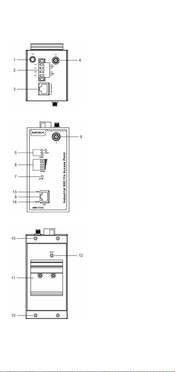
Panel Layout of the AWK-1131A
System LEDs: PWR, FAULT, and
10.
mounting kit
11.
12.
13.
14.
Top Panel View
Front Panel View
Rear Panel View
1. Grounding screw (M5)
2. Terminal block for PWR1 and
PWR2
3. RS-232 console port
4. Antenna B port
5.
STATE LEDs
6. LEDs for signal strength
7. WLAN LEDs
8. 10/100/1000BaseT(X) RJ45
Port
9. Antenna A port
Screw hole for wall DIN-rail mounting kit
Reset button
10/100M LED
1000M LED
- 4 -
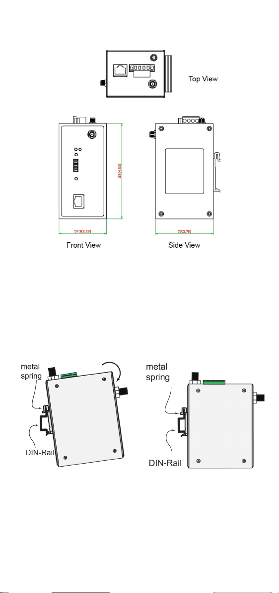
Mounting Dimensions
STEP 1:
Insert the top of the DIN r
slot just below the stiff metal spring.
STEP 2:
The DIN
snap into place as shown below.
Unit = mm (inch)
DIN-Rail Mounting
The aluminum DIN-rail attachment plate should be fixed to the back panel
of the AWK-1131A when you take it out of the box. If you need to reattach
the DIN-rail attachment plate to the AWK-1131A, make sure the stiff
metal spring is situated towards the top, as shown in the figures below.
ail into the
-rail attachment unit will
To remove the AWK-1131A from the DIN rail, simply reverse Steps 1 and
2.
- 5 -

Wall Mounting (optional)
STEP 1:
Remove the aluminum
DIN
from the AWK
then attach the wall mount
plates with M
shown in the adjacent
diagrams.
STEP 2:
Mounting the AWK-1131A to a wall requires 4 screws.
Use the AWK
attached, as a guide to mark the correct locations of
the 4 screws. The heads of the screws should be less
than 6.0 mm in diameter, and the shafts should be less
than 3.5 mm in diameter, as shown in the figure at the
right.
NOTE
Test the screw head and shank size by inserting the screws into
one of the k
lates
before attaching the plate to the wall.
STEP 3:
Once the screws are fixed into
the wall, insert the
heads through the large opening
of the keyhole
apertures, and then slide the
AWK
indicated to the right. Tighten
the four screws for added
stability.
For some applications, it may be more convenient to mount the
AWK-1131A to a wall, as illustrated below.
-rail attachment plate
-1131A, and
3 screws, as
-1131A device, with wall mount plates
Do not drive the screws in all the way—leave a space of about 2 mm to
allow room for sliding the wall mount panel between the wall and the
screws.
eyhole shaped apertures of the wall-mounting p
four screw
-shaped
-1131A downwards, as
- 6 -
 Loading...