

Page 1

MC-1200 Series Hardware User’s Manual
Version 1.0, November 2020
www.moxa.com/product
© 2020 Moxa Inc., All rights reserved.
Page 2

MC-1200 Series Hardware User’s Manual
Moxa Americas
Toll
Tel:
Fax:
Moxa China (Shanghai office)
Toll
Tel:
Fax:
Moxa Europe
Tel:
Fax:
Moxa Asia
Tel:
Fax:
Moxa India
Tel:
Fax:
The software described in this manual is furnished under a license agreement and may be used only in accordance with
the terms of that agreement.
Copyright Notice
© 2020 Moxa Inc., All rights reserved.
Trademarks
The MOXA logo is a registered trademark of Moxa Inc.
All other trademarks or registered marks in this manual belong to their respective manufacturers.
Disclaimer
Information in this document is subject to change without notice and does not represent a commitment on the part of
Moxa.
Moxa provides this document as is, without warranty of any kind, either expressed or implied, including, but not limited
to, its particular purpose. Moxa reserves the right to make improvements and/or changes to this manual, or to the
products and/or the programs described in this manual, at any time.
Information provided in this manual is intended to be accurate and reliable. However, Moxa assumes no responsibility for
its use, or for any infringements on the rights of third parties that may result from its use.
This product might include unintentional technical or typographical errors. Changes are periodically made to the
information herein to correct such errors, and these changes are incorporated into new editions of the publication.
Technical Support Contact Information
www.moxa.com/support
-free: 1-888-669-2872
+1-714-528-6777
+1-714-528-6778
+49-89-3 70 03 99-0
+49-89-3 70 03 99-99
+91-80-4172-9088
+91-80-4132-1045
-free: 800-820-5036
+86-21-5258-9955
+86-21-5258-5505
+886-2-8919-1230
-Pacific
+886-2-8919-1231
Page 3

Table of Contents
1. Introduction ...................................................................................................................................... 1-1
Package Checklist ............................................................................................................................... 1-2
Product Features ................................................................................................................................ 1-2
Hardware Specifications ...................................................................................................................... 1-2
Hardware Block Diagram ..................................................................................................................... 1-2
2. Hardware Introduction...................................................................................................................... 2-1
Appearance ........................................................................................................................................ 2-2
Dimensions ........................................................................................................................................ 2-3
LED Indicators .................................................................................................................................... 2-3
3. Hardware Connection Description ..................................................................................................... 3-1
Installing the MC-1200 ........................................................................................................................ 3-2
Wiring Requirements ........................................................................................................................... 3-4
Connecting the Power .................................................................................................................. 3-4
Grounding the Unit ...................................................................................................................... 3-5
Connecting to a Network ..................................................................................................................... 3-5
Connecting to a Serial Device ............................................................................................................... 3-6
Connecting to a USB Device ................................................................................................................. 3-6
Connecting to an HDMI Device ............................................................................................................. 3-7
Installing Communications Modules ....................................................................................................... 3-7
Installing the mSATA Module ........................................................................................................ 3-8
Installing the Wi-Fi Module ........................................................................................................... 3-8
Installing the Cellular Module ...................................................................................................... 3-12
RTC Battery Replacement .................................................................................................................. 3-16
4. BIOS Setup ........................................................................................................................................ 4-1
Entering the BIOS Setup ...................................................................................................................... 4-2
Main Page .......................................................................................................................................... 4-3
Advanced Settings .............................................................................................................................. 4-4
Intel Rapid Storage Technology ..................................................................................................... 4-7
CPU Configuration ....................................................................................................................... 4-8
Video Configuration ..................................................................................................................... 4-9
Chipset Configuration................................................................................................................. 4-10
SIO ITE8786E ........................................................................................................................... 4-11
Console Redirection ................................................................................................................... 4-12
Security Settings .............................................................................................................................. 4-13
Current TPM Device ................................................................................................................... 4-13
TPM State................................................................................................................................. 4-13
Clear TPM ................................................................................................................................. 4-13
Set Supervisor Password ............................................................................................................ 4-14
Power Settings ................................................................................................................................. 4-15
Wake on LAN ............................................................................................................................ 4-15
Auto Wake on S5 ...................................................................................................................... 4-15
mPCIE#1 Power ........................................................................................................................ 4-15
mPCIE#2 Power ........................................................................................................................ 4-16
Boot Settings ................................................................................................................................... 4-16
Boot Type ................................................................................................................................. 4-16
Network Stack .......................................................................................................................... 4-16
PXE Boot capability .................................................................................................................... 4-16
USB Boot ................................................................................................................................. 4-17
Timeout ................................................................................................................................... 4-17
EFI .......................................................................................................................................... 4-17
Exit Settings .................................................................................................................................... 4-17
Exit Saving Changes .................................................................................................................. 4-17
Save Change Without Exit .......................................................................................................... 4-17
Exit Discarding Changes ............................................................................................................. 4-18
Load Optimal Defaults ................................................................................................................ 4-18
Load Custom Defaults ................................................................................................................ 4-18
Save Custom Defaults ................................................................................................................ 4-18
Discard Changes ....................................................................................................................... 4-18
Enabling AMT ................................................................................................................................... 4-19
Using AMT ....................................................................................................................................... 4-22
Upgrading the BIOS .......................................................................................................................... 4-23
A. Regulatory Approval Statement ........................................................................................................ A-1
Page 4

1
1. Introduction
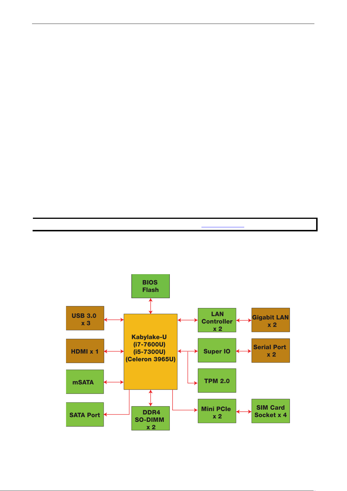
The MC-1200 Series computers are built around a 7th Gen Intel® Celeron® or Intel® Core™ i3, i5, or i7
processor and come with 1 HDMI display port, 3 USB 3.0 ports, 2 gigabit LAN ports, and 2 3-in-1
RS-232/422/485 serial ports. The MC-1200 is equipped with a 2.5” HDD/SSD slot and a built-in TPM 2.0
module.
Additional value and convenience is provided through a modular design with three independent slots for flexible
system integration and expansion. Users have the option to add a variety of different communications modules,
including Wi-Fi, 3G, LTE, GPS, and mSATA expansion modules.
The MC-1200 is designed to operate reliably in extreme conditions, such as continuous exposure to low or high
temperatures, humidity, high vibration, and power surges, making them perfect for heavy industry, solar grid,
water/wastewater, oil and gas, and transportation applications.
The following topics are covered in this chapter:
Package Checklist
Product Features
Hardware Specifications
Hardware Block Diagram
Page 5
MC-1200 HW UM Introduction
1-2
NOTE
The latest specifications for Moxa’s products can be found at https://moxa.com.
Package Checklist
• MC-1200 embedded computer
• Terminal block to power jack converter
• DIN-rail mounting kit
• Quick installation guide (printed)
• Warranty card
NOTE: Please notify your sales representative if any of the above items are missing or damaged.
Product Features
MC-1200 embedded computers comes with the following:
• Mini-PCIe sockets for Wi-Fi, 3G, LTE, GPS, and mSATA expansion modules
• 7th Gen Intel® Core™ processor (Kaby Lake U)
• Built-in DDR4 memory slots; total capacity up to 32 GB
• ATEX and IECEx Zone 2 compliance
• Built-in TPM 2.0 module
• Variety of interfaces: 2 serial ports, 2 Giga LANs, 3 USB 3.0 (type A) ports
Hardware Specifications
Hardware Block Diagram
Page 6

2
2. Hardware Introduction
The MC-1200 Series embedded computers are compact, well designed, and rugged enough for industrial
applications. LED indicators help you monitor the performance and identify trouble spots. Multiple serial ports
allow you to connect different devices for wireless operation and the reliable and stable hardware platform lets
you devote your attention to developing your applications.
The following topics are covered in this chapter:
Appearance
Dimensions
LED Indicators
Page 7
MC-1200 HW UM Hardware Introduction
2-2
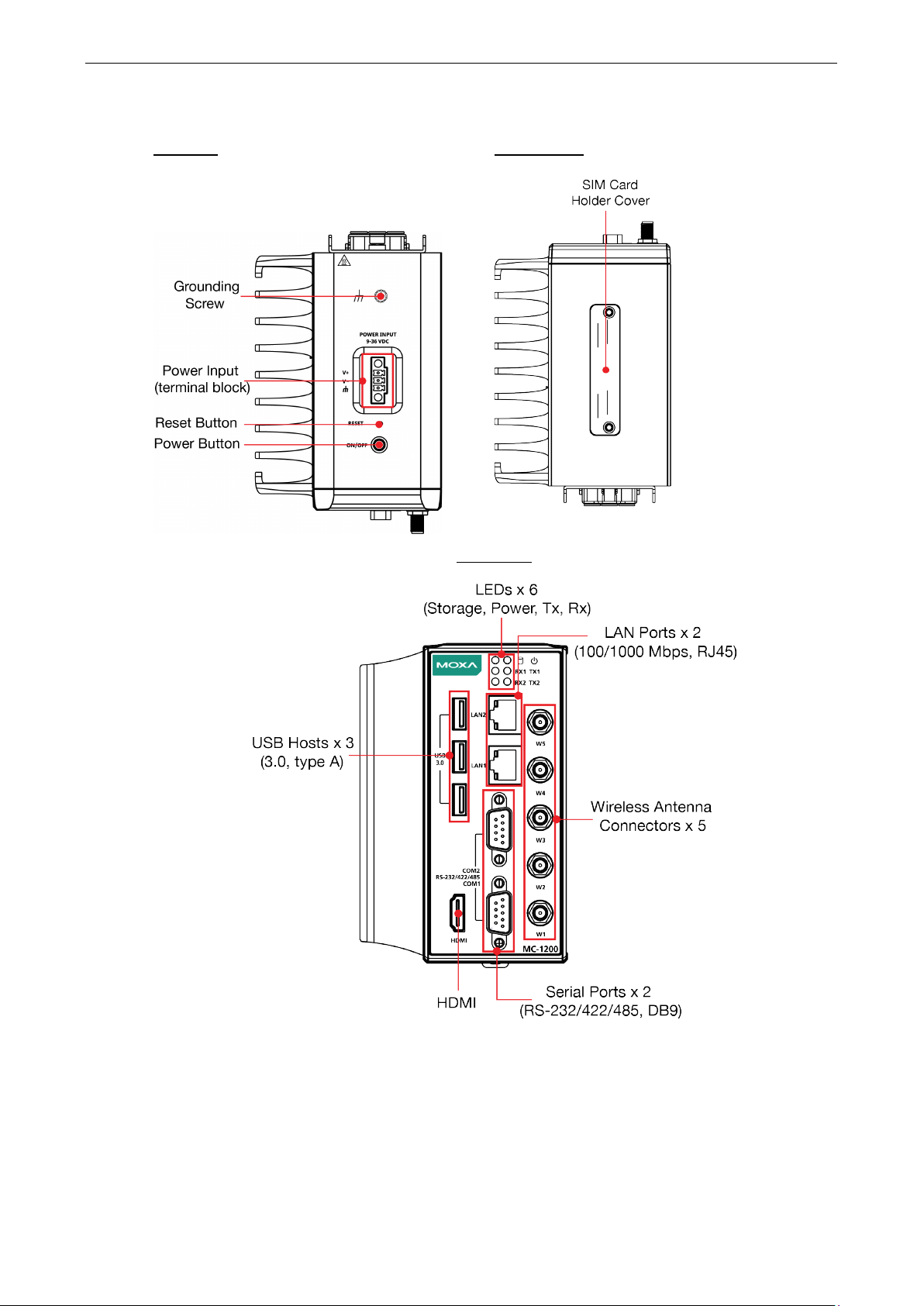
Top View
Bottom
Appearance
Front View
View
Page 8
MC-1200 HW UM Hardware Introduction
2-3
Green
Blinking: Data is being transmitted
Off
No connection
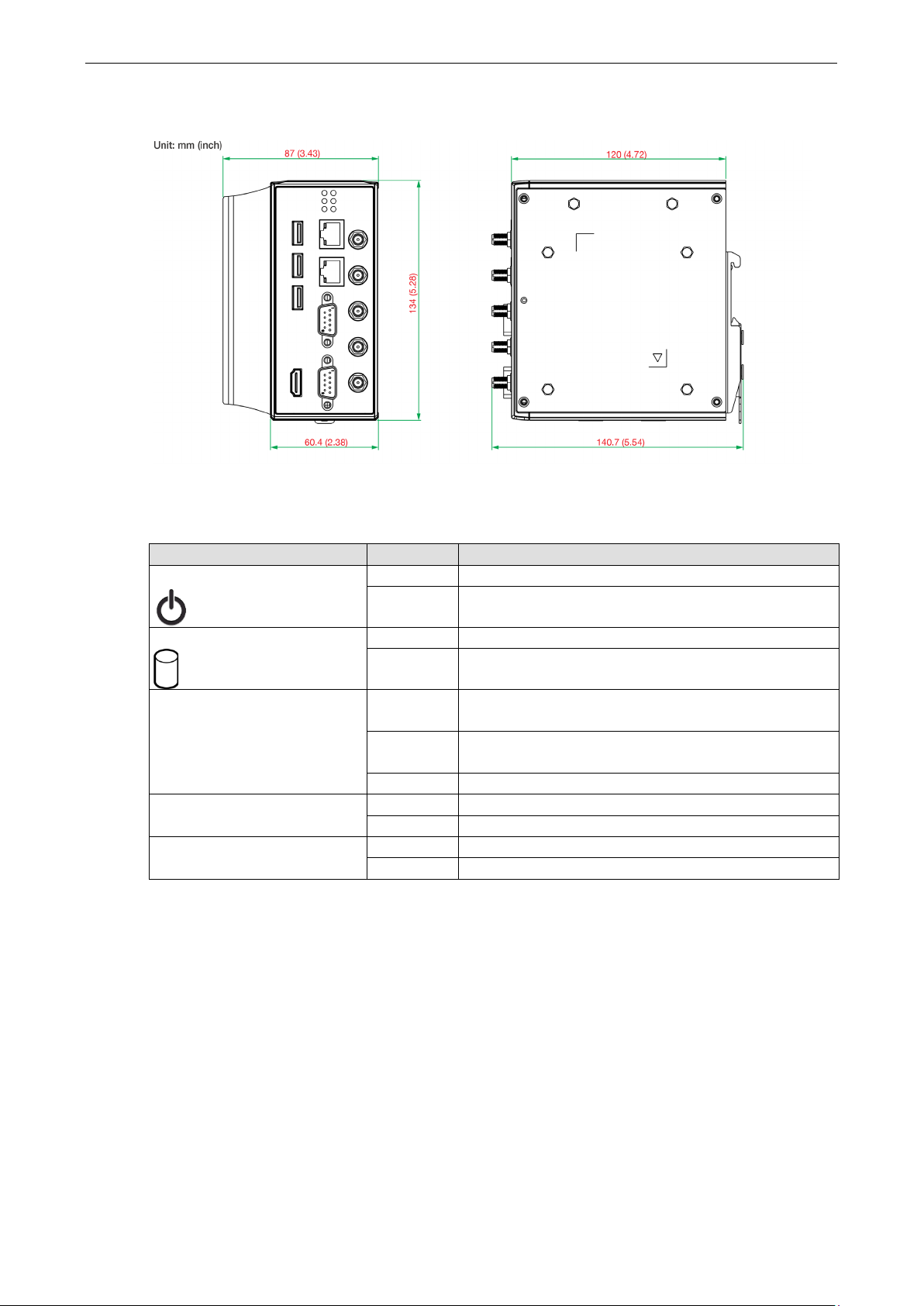
Dimensions
LED Indicators
LED Name Status Function
Power
Storage 1 (mSATA)
LAN ½
(on connectors)
Tx 1/2
Rx 1/2
Green Power is on and computer is functioning normally
Off Power is off
Yellow Blinking: Data transmission
Off No data transmission.
Green Steady On: 100 Mbps Ethernet link
Blinking: Data is being transmitted
Yellow Steady On: 1000 Mbps Ethernet link
Blinking: Data is being transmitted
Off 10 Mbps Ethernet link or LAN is not connected
Off No connection
Yellow Blinking: Data is being transmitted
Page 9

3
3. Hardware Connection Description
In this chapter, we describe how to connect the embedded computer to the network and to various devices.
The following topics are covered in this chapter:
Installing the MC-1200
Wiring Requirements
Connecting the Power
Grounding the Unit
Connecting to a Network
Connecting to a Serial Device
Connecting to a USB Device
Connecting to an HDMI Device
Installing Communications Modules
Installing the mSATA Module
Installing the Wi-Fi Module
Installing the Cellular Module
RTC Battery Replacement
Page 10
MC-1200 HW UM Hardware Connection Description
3-2
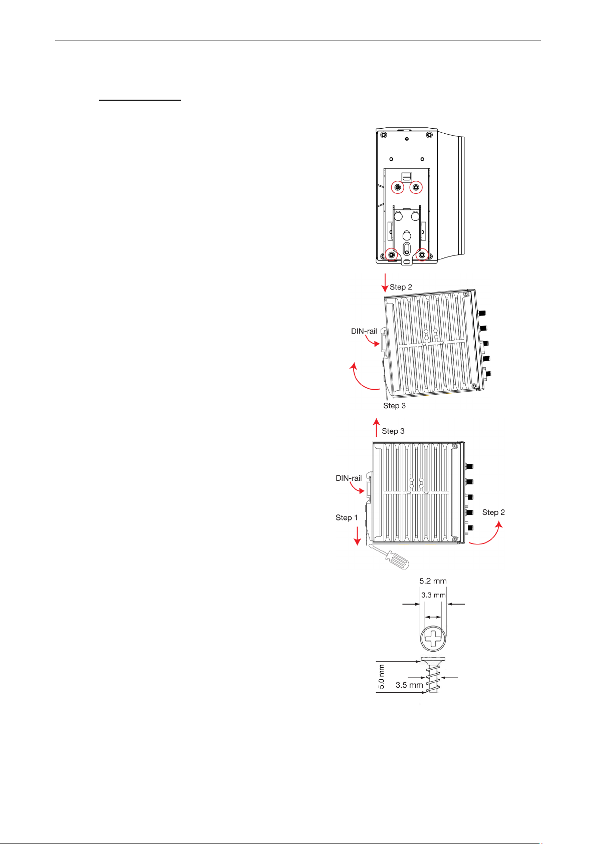
Installing the MC-1200
DIN-rail Mounting
The MC-1200 comes with a DIN-rail mounting kit for installing the computer on a DIN rail.
Installation
STEP 1:
Use the 4 screws included with the kit to attach the
DIN-rail mounting bracket to the MC-1200’s rear
panel and tighten the screws to secure the bracket
to the MC-1200.
STEP 2:
Insert the top of the DIN rail into the slot just below
the upper hook of the DIN-rail mounting kit.
STEP 3:
Press the MC-1200 towards the DIN rail until it
snaps into place.
Removal
STEP 1:
Pull down the latch on the mounting kit with a
screwdriver.
STEP 2 & 3:
Slightly pull the MC-1200 forward and lift it up to
remove it from the DIN rail.
For the specifications of the DIN-rail mounting
screws, refer to the illustrations on the right and
adhere to these values to tighten the DIN-rail
bracket on to the rear of the computer.
Page 11
MC-1200 HW UM Hardware Connection Description
3-3
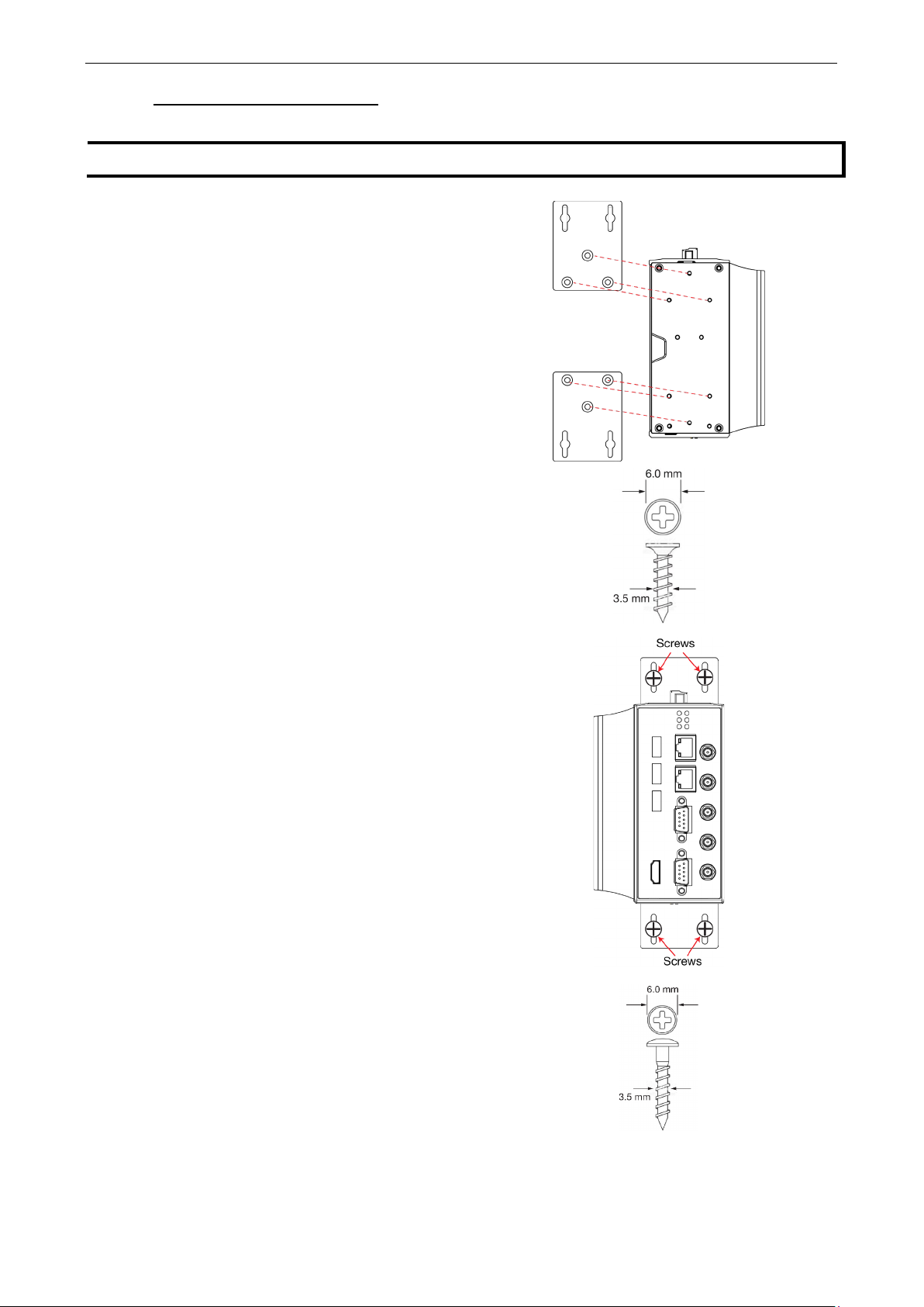
NOTE
The wall
STEP 1:
Use three screws for each bracket and attach the
brackets to the rear of the
Refer to the figure on the right for the specifications
of the screws
STEP 2:
Use
to
a wall or cabinet.
Note:
Mounting the MC-1200 to a wall requires four screws.
Use the MC
wall-mount brackets attached, as a guide to mark the
correct locations of the screws. The heads of the
screws should be less than 6.0 mm in diameter, and
the shafts should be less than 3.5 mm in diameter, as
show in the figure on the right.
Do not fasten the screws in all the
leave a space
of about 2 mm to allow room for sliding the wall
mount bracket between the wall and the screws.
Wall or Cabinet Mounting (DNV)
Use the optional wall-mounting kit to install the MC-1200 on to a wall.
-mounting kit can be purchased separately.
MC-1200.
used to attach the brackets.
two screws per bracket to attach the MC-1200
-1200 computer, with the optional
way;
Page 12
MC-1200 HW UM Hardware Connection Description
3-4
ATTENTION
Safety First!
Be sure to disconnect the power cord before installing and/or wiring your
Wiring Caution!
Calculate the maximum possible current in each power wire and common wire. Observe all electrical codes
dictating the maximum current allowable for each wire size. If the current goes above the maximum ratings,
the wiring could overheat, causing serious damage to your equipment.
Temperature Caution!
Be careful when handling the unit. When the unit is plugged in, the internal components generate heat, and
consequently the outer casing may feel hot to the touch.
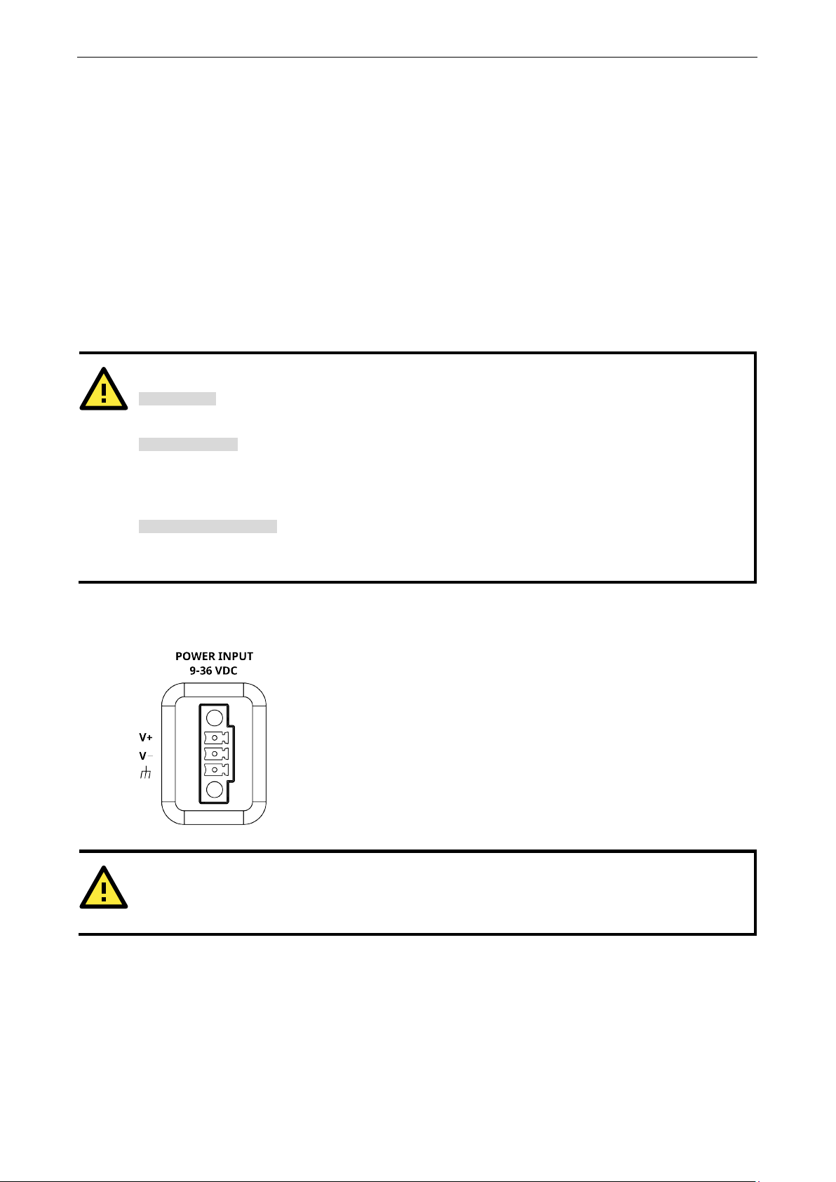
Use an LPS (9
1200's terminal
block to power jack conv
properly, the Power LED will light up. The OS is ready when the Power LED
green.
ATTENTION
This product is intended to be supplied by a Listed Power Supply with output marked LPS and rated to deliver
9 to 36 VDC at a minimum of 8 A.
Wiring Requirements
In this section, we describe how to connect serial devices to the MC-1200 embedded computer.
Be sure to read and follow these common safety precautions before proceeding with the installation of any
electronic device:
• Use separate paths to route wiring for power and devices. If power wiring and device wiring paths must
cross, make sure the wires are perpendicular at the crossing point.
NOTE: Do not run signal or communication wiring together with power wiring in the same wire conduit. To
avoid interference, wires with different signal characteristics should be routed separately.
• Use the type of signal transmitted through a wire to determine which wires should be kept separate. The
rule of thumb is that wiring that shares similar electrical characteristics can be bundled together.
• Keep input wiring and output wiring separated.
• For future reference, you should label the wiring used for all of your devices.
Connecting the Power
MC-1200.
-36 VDC) or Class 2 power cord to connect to the MC-
erter and then turn on the power. If the power is supplied
is solid
Page 13
MC-1200 HW UM Hardware Connection Description
3-5
noise due to electromagnetic interference (EMI). Run
surface prior to connecting the
connect a network cable to the embedded computer’s
Ethernet port and connect the other end of the cable
cable is properly
Two 10/100/1000 Mbps Ethernet ports
connectors are located on the front panel of the
embedded computer. Refer to the
right for the location of the
NOTE
Th
want
to use
Ethernet
cable.
6
ERx-
TRD(1)-
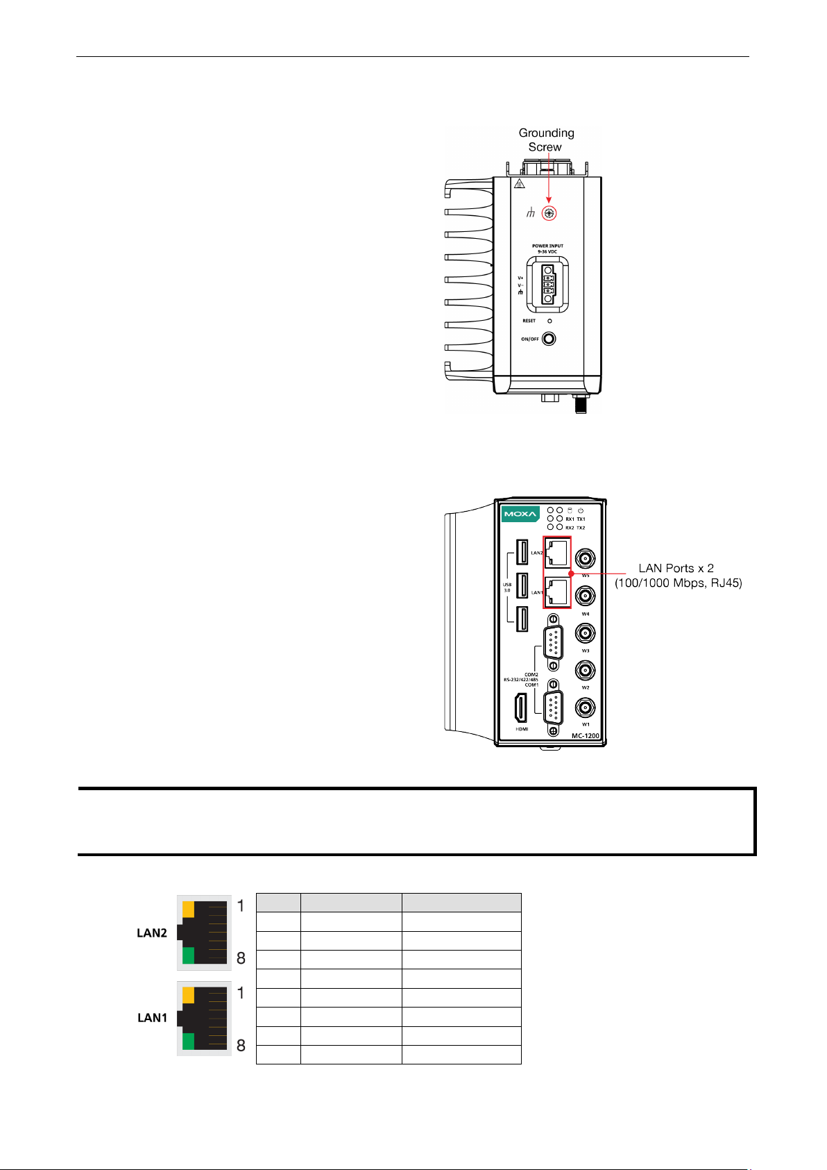
Grounding the Unit
Grounding and wire routing help limit the effects of
the ground connection from the grounding screw
(M4) to the grounding
power.
Connecting to a Network
To connect the MC-1200 computer to a network,
to your Ethernet network. When the
connected, the LEDs on the embedded computer’s
Ethernet port turn on to indicate a valid connection.
e pin assignments for the MC-1200 computer’s Ethernet port are shown in the following figure. If you
your own Ethernet cable, ensure that you match the pin assignments of the connector on the
Pin 10/100 Mbps 1000 Mbps
1 ETx+ TRD(0)+
2 ETx- TRD(0)-
3 ERx+ TRD(1)+
4 – TRD(2)+
5 – TRD(2)-
with RJ45
illustration n the
Ethernet ports.
7 – TRD(3)+
8 – TRD(3)-
Page 14
MC-1200 HW UM Hardware Connection Description
3-6
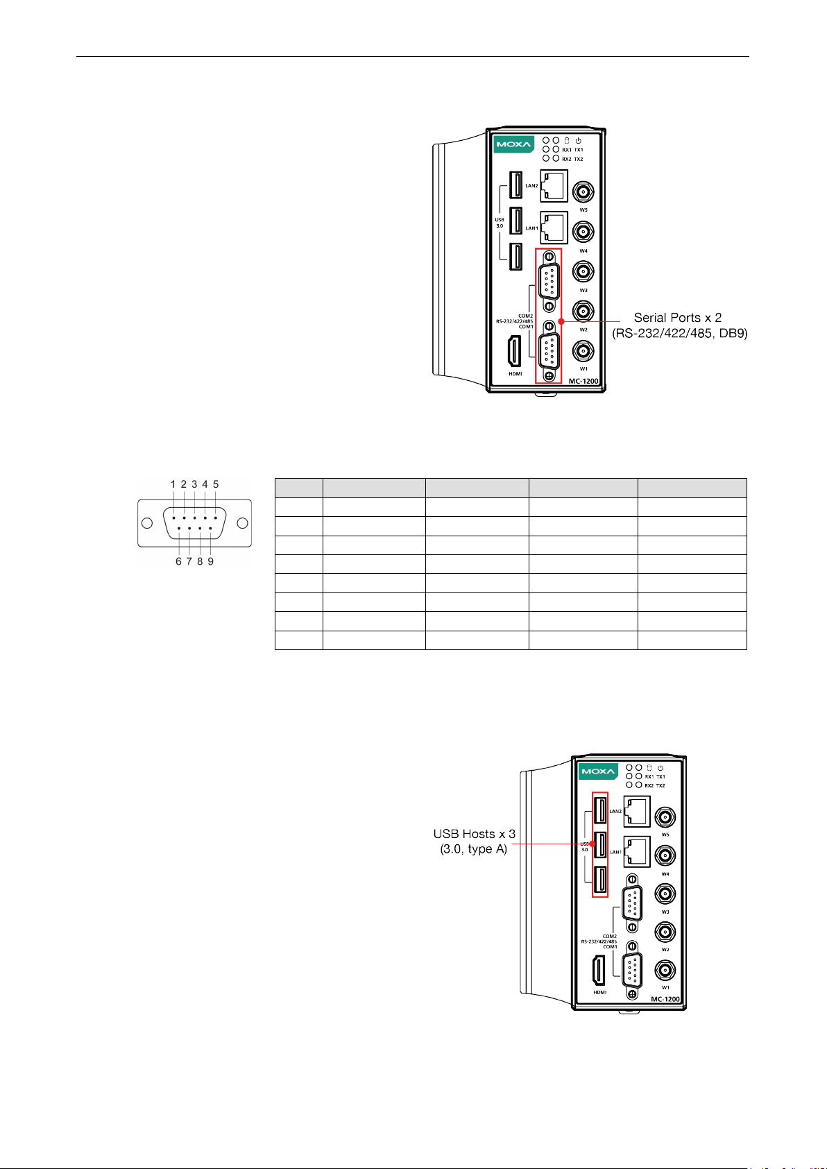
Use a serial cable to connect your serial device to
the embedded computer’s serial port.
ports P1 to P2 have male DB9 connectors and can
be configured for RS
communication. For information on serial port
configuration, ref
manual
DB9 Male Port
RS
2
RxD
TxDB(+)
TxDB(+)
–
5
GND
GND
GND
GND
The MC
with type
ports can be used to connect to an external flash disk
or hard drive. You can also use these USB ports to
connect to a keyboard or a mouse.
Connecting to a Serial Device
The serial
-232, RS-422, or RS-485
er to the MC-1200 software
.
The pin assignments of the serial ports are shown in the following table:
-232/422/485 Pinouts
Pin RS-232 RS-422 RS-485 (4-wire) RS-485 (2-wire)
1 DCD TxDA(-) TxDA(-) –
3 TxD RxDB(+) RxDB(+) DataB(+)
4 DTR RxDA(-) RxDA(-) DataA(-)
6 DSR – – –
7 RTS – – –
8 CTS – – –
Connecting to a USB Device
-1200 is provided with three USB 3.0 ports
-A connectors on the front panel. These
Page 15
MC-1200 HW UM Hardware Connection Description
3-7
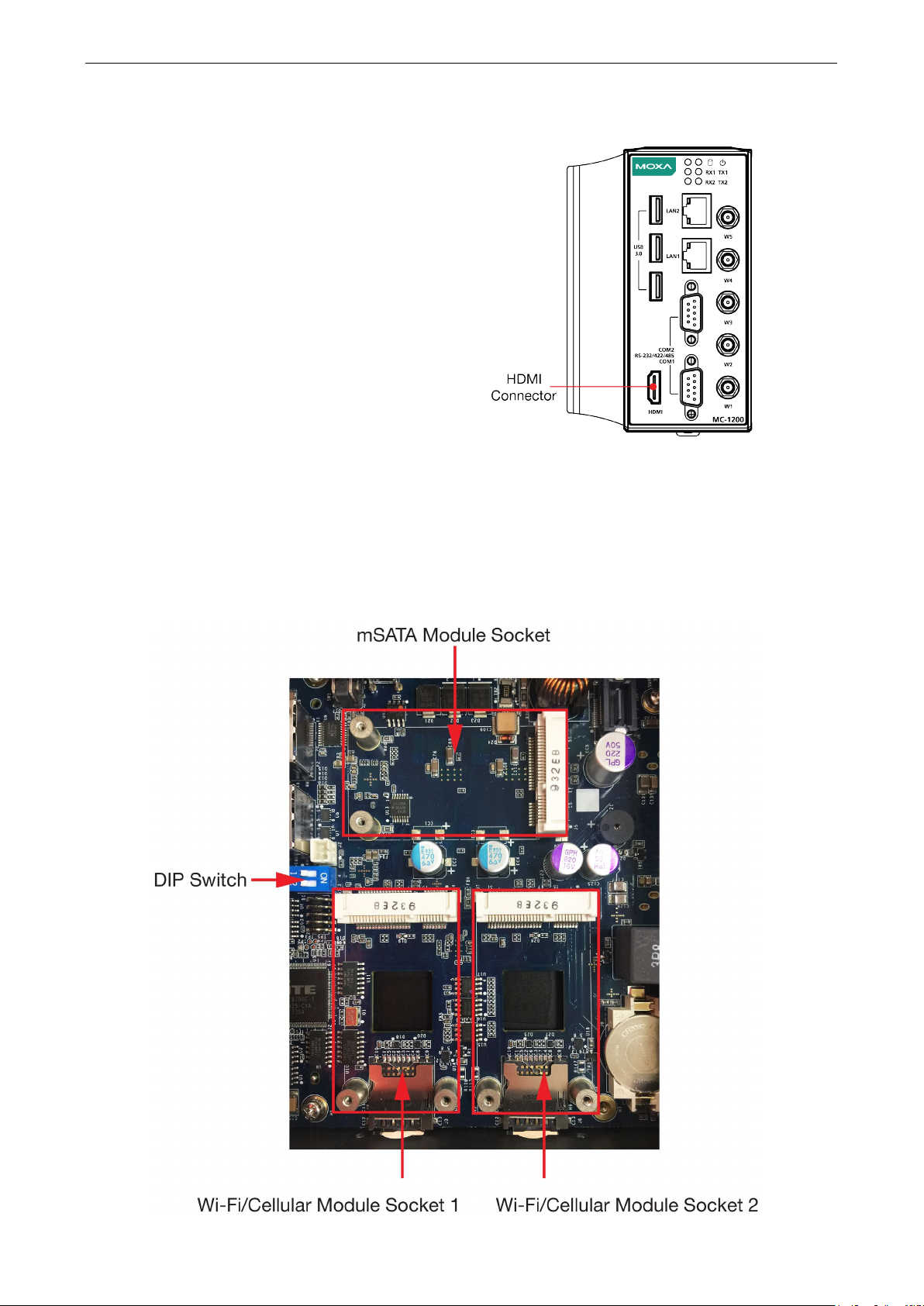
Connecting to an HDMI Device
The MC-1200 Series offers an HDMI connector
located on the front panel, allowing users to connect
to an audio or video device. Make sure you use an
HDM-certified cable for a reliable audio or video
connection.
Installing Communications Modules
The MC-1200 Series comes with three sockets for installing various communications modules. Unfasten the
screws on the right side of the computer and remove the cover to find the locations of these sockets as shown
below:
Page 16
MC-1200 HW UM Hardware Connection Description
3-8
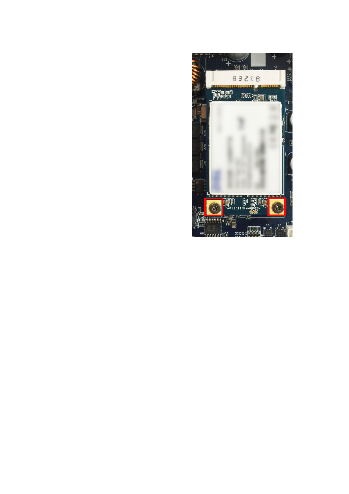
Insert the mSATA module into the socket and tighter
the two screws on the mSATA module to secure it.
Installing the mSATA Module
Installing the Wi-Fi Module
The MC-1200 comes with two sockets for users to install up to two Wi-Fi/cellular modules for wireless
communication.
Wi-Fi Module Package
The contents of the Wi-Fi module package are shown below:
Page 17

MC-1200 HW UM Hardware Connection Description
3-9
Follow these steps to install the Wi-Fi module in the MC-1200.
1. Attach the Wi-Fi module to the mounting plate
with two screws.
Page 18

MC-1200 HW UM Hardware Connection Description
3-10
sides of the thermal pad and then
2. Remove the transparent plastic and the blue
cover on both
place it on the top heat sink. Also, remove the
blue cover on the heat sink.
3. Place the heat sink with the thermal pad at the
center of the wireless module socket.
4. Insert the Wi-Fi module (with the mounting
plate) into the socket and fasten the two black
screws on the mounting plate to secure it.
Page 19

MC-1200 HW UM Hardware Connection Description
3-11
Fi antenna cable to the
Fi module and the insert the
g hole on the front
Insert the locking washer through the threaded
panel. Secure the antenna connector in place by
Reattach the right side cover on to the computer
5. Attach one end of the Wi-
connector on the Wi-
other end (with the threaded connection ring)
through the antenna mountin
panel of the computer.
Remove the protection cover on the mounting
hole before you do so.
6.
connection ring and hold it against the front
tightening a nut onto the threaded protection
ring.
7. Connect the Wi-Fi antenna to the connector on
the front panel.
8. Use this method to connect another Wi-Fi
antenna, if necessary.
9.
and fasten the screws to secure it.
Page 20

MC-1200 HW UM Hardware Connection Description
3-12
covers on both sides of the thermal pad and then
place it on top of the heat sink. Also, remove the
Installing the Cellular Module
The MC-1200 comes with two sockets for users to install up to two Wi-Fi/cellular modules for wireless
communication.
Cellular Module Package
The contents of the Wi-Fi module package are shown below:
Follow these steps to install the cellular module in the MC-1220.
1. Remove the transparent plastic and the blue
blue cover on the heat sink.
Page 21

MC-1200 HW UM Hardware Connection Description
3-13
2. Place the heat sink with the thermal pad at the
center of the cellular module socket.
3. Insert the cellular module in the socket and
fasten the two black screws on the module to
secure it.
4. There are three connectors on the cellular
module: a GPS antenna connector and two
cellular antenna connectors.
Page 22

MC-1200 HW UM Hardware Connection Description
3-14
Attach one end of the cellular antenna cable to a
connector on the cellular module and the insert
ring) through the antenna mounting hole on the
Insert the locking washer through the threaded
panel. Secure the antenna connector in place by
Reattach the right side cover on to the computer
5.
the other end (with the threaded connection
front panel of the computer.
Remove the protection cover on the mounting
hole before you do so.
6.
connection ring and hold it against the front
tightening a nut onto the threaded protection
ring.
7. Connect the cellular antenna to the connector
provided on the front panel.
8. Use this method to connect another cellular
antenna and the GPS antenna, if necessary.
9.
and fasten the screws to secure it.
Installing SIM Cards
Follow these steps to install SIM cards for a cellular module.
Page 23

MC-1200 HW UM Hardware Connection Description
3-15
Insert a card into the SIM 1 slot. Make sure you
insert the card in the right direction as indicated
1. Remove the screws on the bottom panel of the
computer and remove the cover. You will see
four SIM card slots.
2.
in the image beside the slot.
3. Insert the other card into the SIM 2 slot, if
necessary.
4. Replace the computer cover and secure it by
fastening the screws.
Switching Between the Wireless Module Socket
As there are two wireless module sockets and you can install the Wi-Fi or the cellular module in either of the
sockets, a DIP switch is provided to enable selection of the Wi-Fi or cellular module installed. The DIP switch is
located below the mSATA socket as shown in the following illustration.
Page 24

MC-1200 HW UM Hardware Connection Description
3-16
For example, if you
socket, you need to turn the DIP switch 1 to
ATTENTION
There is a risk of explosion if the battery is replaced by
NOTE
The
embedded computer can be customized to support an easy RTC battery replacement function.
Please contact your Moxa sales representative for details.
The DIP switch operation is explained below:
Status Switch 1 Switch 2
ON Wi-Fi Wi-Fi
OFF (default) Cellular Cellular
RTC Battery Replacement
The MC-1200’s real-time clock is powered by a lithium battery. We strongly recommend that you do not replace
the lithium battery without help from a qualified Moxa support engineer. If you need to change the battery,
contact the Moxa RMA service team.
have installed a Wi-Fi module in the first
the ON status.
an incorrect type of battery.
MC-1200
Page 25

4
4. BIOS Setup
In this chapter, we describe the BIOS settings for the MC-1200 embedded computer. The BIOS is a set of
input/output control routines for peripherals to initialize the basic settings. The BIOS firmware helps boot the
system before the operating system is loaded. The BIOS setup allows the user to modify the system
configuration for basic input/output peripherals. All the configurations are stored in the CMOS RAM, which has
backup battery in case the computer is not connected to a power source. Consequently, the data stored in the
CMOS RAM is retained when the system is rebooted or the power is disconnected.
The following topics are covered in this chapter:
Entering the BIOS Setup
Main Page
Advanced Settings
Intel Rapid Storage Technology
CPU Configuration
Video Configuration
Chipset Configuration
SIO ITE8786E
Console Redirection
Security Settings
Current TPM Device
TPM State
Clear TPM
Set Supervisor Password
Power Settings
Wake on LAN
Auto Wake on S5
mPCIE#1 Power
mPCIE#2 Power
Boot Settings
Boot Type
Network Stack
PXE Boot capability
USB Boot
Timeout
EFI
Exit Settings
Exit Saving Changes
Save Change Without Exit
Exit Discarding Changes
Load Optimal Defaults
Load Custom Defaults
Save Custom Defaults
Discard Changes
Enabling AMT
Using AMT
Upgrading the BIOS
Page 26

MC-1200 HW UM BIOS Setup
4-2
F1
F5/ F6
F9
F10
General Help
Change Values
Setup Defaults
Save and Exi
↑↓.
←→
ESC
EN TER
Select Item
Select Menu
Exit
Select or go to Submenu.
Entering the BIOS Setup
To enter the BIOS setup utility, press the F2 key while the system is booting up. The main BIOS Setup screen
will appear. You can configure the following settings on this screen.
• Continue: Continue to boot up
• Boot Manager: Select the device for booting up
• Device Manager:
• Boot From File: Select the UEFI boot up file
• Setup Utility: Enter the BIOS configuration menu
• Intel® Management Engine BIOS Extension: Enter the AMT configuration menu (not supported in the
KL1 model)
Select F2 to enter the BIOS configuration.
Enter the device configuration menu
When you enter Setup Utility, a basic description of each function key is listed at the bottom of the screen.
Refer to these descriptions to learn how to use them.
t
Page 27

MC-1200 HW UM BIOS Setup
4-3
The BIOS configuration screen will be shown when you enter the Setup Utility option, as shown in the
following figure:
Note that the Processor Type information will vary depending on the model that you have purchased.
Main Page
The Main page displays basic system hardware information, such as model name, BIOS version, and CPU type.
Page 28

MC-1200 HW UM BIOS Setup
4-4
Advanced Settings
Select the Advanced tab in the main menu to open the advanced features screen.
Page 29

MC-1200 HW UM BIOS Setup
4-5
Boot Configuration
This item allows users to configure the default value of Numlock.
Options: On (default), Off.
SATA Configuration
You can use this setting to select the mode for the host drive controller. Options are AHCI (default) and Intel
RST Premium.
Page 30

MC-1200 HW UM BIOS Setup
4-6
Serial ATA Port
This setting displays information on the installed drives.
SATA Port Hot Plug
This setting allows you to enable/disable hot-plugging capabilities (the ability to remove the drive while the
computer is running) that are configured by software for installed storage drives.
Options: Disabled (default for Port 0), Enabled (default for Port 1)
RAID
Set HDC configuration as “Intel RST Premium” to enable redundant array of inexpensive disks technology. The
MC-1200 has three SATA interfaces, which only support RAID level 0 and Recovery.
Recovery utilizes RAID 1 (mirroring) functionality to copy data from a designated master drive to a designated
recovery drive. The master drive data can be copied to the recovery drive either continuously or on request.
When using the continuous update policy, changes made to the data on the master drive while the system is
not docked are automatically copied to the recovery drive when the system is re-docked. When using the on
request update policy, the master drive data can be restored to a previous state by copying the data on the
recovery drive back to the master drive.
Source: http://en.wikipedia.org/wiki/Standard_RAID_levels for details.
Page 31

MC-1200 HW UM BIOS Setup
4-7
Return to Front Page, and select Device Management.
When setting the Intel RST Premium mode, or saving changes and reboot, you can select Device
Management to configure the following Intel Rapid Storage Technology.
Intel Rapid Storage Technology
This section allows users to configure Intel® Rapid Storage Technology.
Page 32

MC-1200 HW UM BIOS Setup
4-8
NOTE
The Hyper Threading function is not supported in the KL1 models.
CPU Configuration
Page 33

MC-1200 HW UM BIOS Setup
4-9
Active Processor Cores
This item indicates the number of cores to enable in each processor package.
Hyper-Threading
This feature makes the processor resources work more efficiently, enabling multiple threads to run on each
core. It also increases processor throughput, improving overall performance on threaded software.
Options: Disabled, Enabled (default)
Video Configuration
DVMT Pre-Allocated
This item allows you to configure pre-allocated memory capacity for the IGD. Pre-allocated graphics memory
is invisible to the operating system.
Options: 12 M, 16M, 20M, 24M, 28M, 32M (default), 36M, 40M, 44M, 48M, 52M, 56M, 60M, 64M
DVMT: The amount of video memory your computer has is dependent on the amount of pre-allocated memory
set for your system plus the Dynamic Video Memory Technology (DVMT). DVMT dynamically allocates system
memory for use as video memory creating the most efficient use of available resources for maximum 2D/3D
graphics performance.
DVMT Total Gfx Mem.
This item allows you to configure the maximum amount of memory DVMT will use when allocating additional
memory for the internal graphics device.
Options: 256 MB (default), 128 MB, Max.
Page 34

MC-1200 HW UM BIOS Setup
4-10
Chipset Configuration
This item allows you to configure the chipset settings.
Power ON after Power Failure
This item allows you to enable/disable the computer from automatically powering up after system power is
re-enabled.
Options: ON (default), OFF, Last State
Page 35

MC-1200 HW UM BIOS Setup
4-11
SIO ITE8786E
This section allows users to configure serial port settings.
Serial Port A
This function allows users to configure the resources for the serial port A.
Disable: No resources
Enable: User configures the resources
Auto (default): EFI/OS chooses the resources
Serial Port B
This function allows users to configure the resources for the serial port B.
Disable: No resources
Enable: User configures the resources
Auto (default): EFI/OS chooses the resources
Page 36

MC-1200 HW UM BIOS Setup
4-12
Hardware Monitor
This item allows you to view stats such as CPU and system temperature, voltage levels, and other chipset
information.
Console Redirection
When the Console Redirection Function is enabled, the console information will be output to both the HDMI
monitor and through the serial port.
Options: Disabled (default), Enabled
Page 37

MC-1200 HW UM BIOS Setup
4-13
Security Settings
This section allows users to configure security-related settings with a supervisor password and user password.
Current TPM Device
This item shows if the system has TMP device and its type.
TPM State
This item allows you view the status of current TPM settings.
Clear TPM
This item allows users to remove all TPM context associated with a specific owner.
Page 38

MC-1200 HW UM BIOS Setup
4-14
Set Supervisor Password
This item allows you to set the supervisor password. Select the Set Supervisor Password option and enter
the password and confirm the password again.
To delete the password, select the Set Supervisor Password option and enter the old password; leave the
new password fields blank, and then press enter.
After setting the supervisor password, users can choose when asking input password screen will pop up.
Page 39

MC-1200 HW UM BIOS Setup
4-15
Enable: System will ask input password on post time.
Disable: System will ask for the password to go to the setup utility.
Config-Only: System will only ask for the password when you select the config (F2) option
Power Settings
The section allows users to configure power settings.
Wake on LAN
This feature is used to wake the system by a LAN device from a remote host.
Options: Enabled (default), Disabled
Auto Wake on S5
This item allows you to configure the computer to wake from S5 status. S5 stands for Soft Off, where the PSU
remains engaged but power to all other parts of the system is cut. Auto-wake on S5 schedules a soft-reboot at
certain periodic times that may be specified in the BIOS.
Options: Disabled (default); By Every Day (user specifies a regular daily time when the computer will power
up); By Day of Month (user specifies a regular day each month when the computer will power up)
mPCIE#1 Power
This item allows you to control the power in the 1st mPCIe connector.
Options: Off (default), on
Page 40

MC-1200 HW UM BIOS Setup
4-16
NOTE
If you do not add any storage, you will not see the EFI option.
mPCIE#2 Power
This item allows you to control the power in the 2nd mPCIe connector.
Options: Off (default), on
Boot Settings
The section allows users to configure boot settings.
Boot Type
This item allows you to enable/disable the quick boot function.
Options: Dual Boot Type, Legacy Boot Type, UEFI Boot Type (default)
Network Stack
It deploys an Internet Protocol (IP) stack. The IP stack provides an application library to open/close
connections to remote devices and send/receive data between the remote devices.
Options: Disabled (default), Enabled
PXE Boot capability
PXE Booting is booting a system over a network. This item allows users to start PXE over IPv4 or IPv6
Options: Disabled (default), UEFI: IPv4, UEFI: IPv6, UEFI: IPv4/IPv6
Page 41

MC-1200 HW UM BIOS Setup
4-17
USB Boot
Set booting to USB boot devices capability.
Options: Enabled (Default), Disabled
Timeout
This item allows users to set the number of second that the firmware will wait before booting the original default
boot selection.
EFI
This item allows users to select the boot order. Use F5 (move down) or F6 (move up) to change the value.
Exit Settings
The section allows users to exit the BIOS environment.
Exit Saving Changes
This item allows you to exit the BIOS environment and save the values you have just configured.
Options: Yes (default), No
Save Change Without Exit
This item allows you to save changes without exiting the BIOS environment.
Options: Yes (default), No
Page 42

MC-1200 HW UM BIOS Setup
4-18
Exit Discarding Changes
This item allows you to exit without saving any changes that might have been made to the BIOS.
Options: Yes (default), No
Load Optimal Defaults
This item allows you to revert to the factory default BIOS values.
Options: Yes (default), No
Load Custom Defaults
This item allows you to load custom default values for the BIOS settings.
Options: Yes (default), No
Save Custom Defaults
This item allows you to save the current BIOS values as a “custom default” that may be reverted to at any time
by the load custom defaults selection.
Options: Yes (default), No
Discard Changes
This item allows you to discard all settings you have just configured.
Options: Yes (default), No
Page 43

MC-1200 HW UM BIOS Setup
4-19
NOTE
The AMT function is not supported
Enabling AMT
To enter the BIOS setup utility, press the “F2” key while the system is booting up. The main BIOS Setup
screen will appear. Five options will be available:
1. Select Intel® Management Engine BIOS Extension to enter the AMT configuration.
in the KL1 models.
2. Press <Enter> to start the login procedure.
Page 44

MC-1200 HW UM BIOS Setup
4-20
3. Type the default password: admin
4. Type the new password. It must include both upper-case and lower-case characters, numbers, and special
symbols. E.g., Admin’12.
5. Select Intel® AMT Configuration to enable remote access without a local user present for consent, select
User Consent, and then select User Opt-in and change the value to None.
Page 45

MC-1200 HW UM BIOS Setup
4-21
6. Set static IP or DHCP by request.
7. Set Activate Network Access to enable remote access capability.
Page 46

MC-1200 HW UM BIOS Setup
4-22
NOTE
The MC
NOTE
For details, r
https://software.intel.com/sites/managea
default.htm?turl=WordDocuments%2Faccessingintelamtviathewebuiinterface.htm
Using AMT
You can use any AMT tool available to run the remote management function using a web browser.
1. Type the IP address of your computer as configured in the AMT configuration settings with port 16992.
The AMT logon screen will appear.
2. Click Log On and type the username (admin) and password.
-1200’s AMT port is LAN1.
efer to the Intel AMT Implementation and Reference Guide at:
bility/AMT_Implementation_and_Reference_Guide/
Page 47

MC-1200 HW UM BIOS Setup
4-23
NOTE
It is possible to permanently damage the computer when upgrading the BIOS. We strongly recommend that
you contact Moxa’s technical support staff for assistance to obtain all the necessary tools and the most current
advice before attempting to upgrade the BIOS on any Moxa device.
Upgrading the BIOS
This section describes how to upgrade the BIOS on your embedded computer.
Step 1: Create a Bootable USB Disk
Before upgrading the BIOS, you must create a bootable USB drive as a system boot device for use in the future.
1. Insert a USB disk in the computer’s USB drive.
2. Search for “format” and select Create and format hard disk partitions.
Page 48

MC-1200 HW UM BIOS Setup
4-24
3. Right-click on the USB disk item and select Format.
4. Select FAT32 and click OK to start formatting the disk.
Step 2: Prepare the Upgrade File
You must use the BIOS upgrade installation file to upgrade the BIOS. Contact Moxa’s technical department for
assistance. The BIOS upgrade file includes an efi folder and an xxxx.efi file. Copy the efi folder and xxxx.efi
file to the bootable USB disk.
Page 49

MC-1200 HW UM BIOS Setup
4-25
ATTENTION
Do NOT switch off the power supply during the BIOS upgrade, since doing so may cause the system to crash.
Step 3: Run the Upgrade Program on Your Computer
1. Reboot the computer with the boot disk and press F2 to go to the Boot Manager.
If the BIOS cannot recognize the USB drive as the boot-up device, the USB drive might not have a partition
table. Use the Windows command line tool diskpart to rebuild the partition table.
2. Select the USB Disk.
The screen will switch to the SHELL environment.
3. Type fs0:, go to the directory where the upgrade file is located, and type xxxxxx.efi (the file name is based
on the upgrade file from Moxa).
4. Wait until the upgrade procedure is completed.
Page 50

MC-1200 HW UM BIOS Setup
4-26
When the upgrade is finished, the computer will automatically reboot.
You may check BIOS version on the Main page to confirm the upgrade.
If the system has more than one boot device, you will see more than one fsx (x represents the number).
5. Go to each fsx (x stands for the number) and type ls to view the content of the boot device.
If you find an upgrade file, run it.
Page 51

This device complies with part 15 of the FCC Rules. Operation is subject to the following
two conditions: (1) This device may not cause harmful interference, and (2) this device
must accept any interference received, including interference that may cause undesired
operation.
European Community
A
A. Regulatory Approval Statement
Class A: FCC Warning! This equipment has been tested and found to comply with the limits for a Class A digital
device, pursuant to part 15 of the FCC Rules. These limits are designed to provide reasonable protection
against harmful interference when the equipment is operated in a commercial environment. This equipment
generates, uses, and can radiate radio frequency energy and, if not installed and used in accordance with the
instruction manual, may cause harmful interference to radio communications. Operation of this equipment in
a residential area is likely to cause harmful interference in which case the users will be required to correct the
interference at their own expense.
Warning:
This is a class A product. If used in a domestic environment, this product may cause undesirable radio
interference, in which case the user may be required to take adequate measures to prevent the interference
from affecting nearby devices.
 Loading...