

Page 1

P/N: 1802020003012
Technical Support Contact Information
www.moxa.com/support
Moxa Americas:
Toll
Tel:
Fax:
Moxa China (Shanghai office):
Toll
Tel:
Fax:
Moxa Europe:
Tel:
Fax:
Moxa Asia-Pacific:
Tel:
Fax:
Moxa India:
Tel:
Fax:
2020 Moxa Inc. All rights reserved.
EDS-2010/2018-ML Series
Quick Installation Guide
Moxa EtherDevice Switch
Version 1.2, November 2020
-free: 1-888-669-2872
1-714-528-6777
1-714-528-6778
+49-89-3 70 03 99-0
+49-89-3 70 03 99-99
+91-80-4172-9088
+91-80-4132-1045
-free: 800-820-5036
+86-21-5258-9955
+86-21-5258-5505
+886-2-8919-1230
+886-2-8919-1231
*1802020003012*
Page 2

Overview
NOTE
Throughout this Quick Installation Guide, we use EDS as an
abbreviation for Moxa EtherDevice Switch:
EDS = Moxa EtherDevice Switch
ATTENTION
This device complies with part 15 of FCC Rules. Operation is
subject to the following two conditions: (1) This device may not
cause harmful interference, and (2) this device must accept any
interference received, including interference that may cause
undesired operation.
The EDS-2010/2018-ML series of industrial Ethernet switches are
equipped with 8/16-ports 10/100M copper ports and 2
10/100/1000BaseT(X) or 100/1000BaseSFP combo ports. The switches
are ideal for applications that require high-bandwidth data convergence
and long-distance uplinks.
The EDS-2010/2018-ML provides 12/24/48 VDC redundant power inputs,
and the switches are available with a standard operating temperature
range from -10 to 60°C, or with a wide operating temperature range from
-40 to 75°C. The switches are rugged enough to operate reliably in harsh
industrial environments.
To provide greater versatility for use with applications from different
industries, the EDS-2010/2018-ML also allow users to enable or disable
broadcast storm protection, Quality of Service (QoS) function, and port
break alarm function with DIP switches on the outer panel.
The EDS-2010/2018-ML switches can be easily installed with DIN-Rail
mounting as well as distribution boxes. The DIN-rail mounting capability
and IP30 metal housing with LED indicators make the plug-and-play
EDS-2010/2018-ML switches reliable and easy to use.
Package Checklist
Your EDS is shipped with the following items. If any of these items are
missing or damaged, please contact your customer service
representative for assistance.
• Moxa EtherDevice™ Switch
• Protective caps for unused ports
• Quick installation guide (printed)
• Warranty card
- 2 -
Page 3

Features
WARNING
The
for this product is intended to be supplied by a Listed
Power Supply, with output marked LPS, and rated to deliver 12 to
48 VDC at a
High Performance Network Switching Technology
• 10/100/1000BaseT(X), 10/100BaseT(X) auto-negotiation speed,
full/half duplex mode, auto MDI/MDI-X connection, and
100/1000Base SFP slot.
• IEEE 802.3 for 10BaseT, IEEE 802.3u for 100BaseT(X), IEEE 802.3ab
for 1000BaseT, and IEEE 802.3z for 1000BaseX.
• IEEE 802.1p for Quality of Service (QoS) traffic prioritized function.
• Store-and-forward switching process type.
Industrial-grade Reliability
• Power failure, port break alarm by relay output
• Redundant dual DC power inputs
• Broadcast storm protection to prevent network devices from crashing
Rugged Design
• Operating temperature range from -10 to 60°C, or extended
operating temperature from -40 to 75°C for “-T” models
• IP30, rugged high-strength case
• DIN-rail or panel mounting ability
power
minimum of 0.62 A.
- 3 -
Page 4
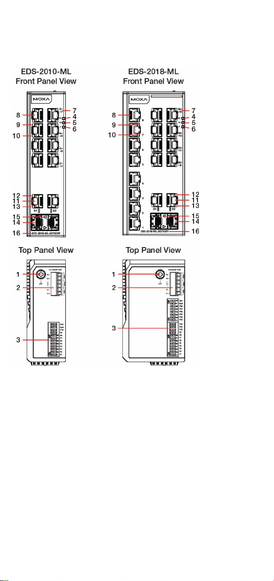
Panel Layout of EDS-2010-ML-2GTXSFP /
EDS-2018-ML-2GTXSFP
1. Grounding screw
2. Terminal block for power input
(PWR1, PWR2) and relay output
3. DIP switch
4. Power input PWR1 LED
5. Power input PWR2 LED
6. Fault LED
7. Port number
8. 10/100 BaseT(X) Port
9. TP port’s 100 Mbps LED
10. TP port’s 10 Mbps LED
11. 10/100/1000 BaseT(X) Port
12. TP port’s 1000 Mbps LED
13. TP port’s 100 Mbps LED
14. 100/1000Base SFP slot
15. SFP port's 100/1000 Mbps LED
16. Model Name
- 4 -
Page 5
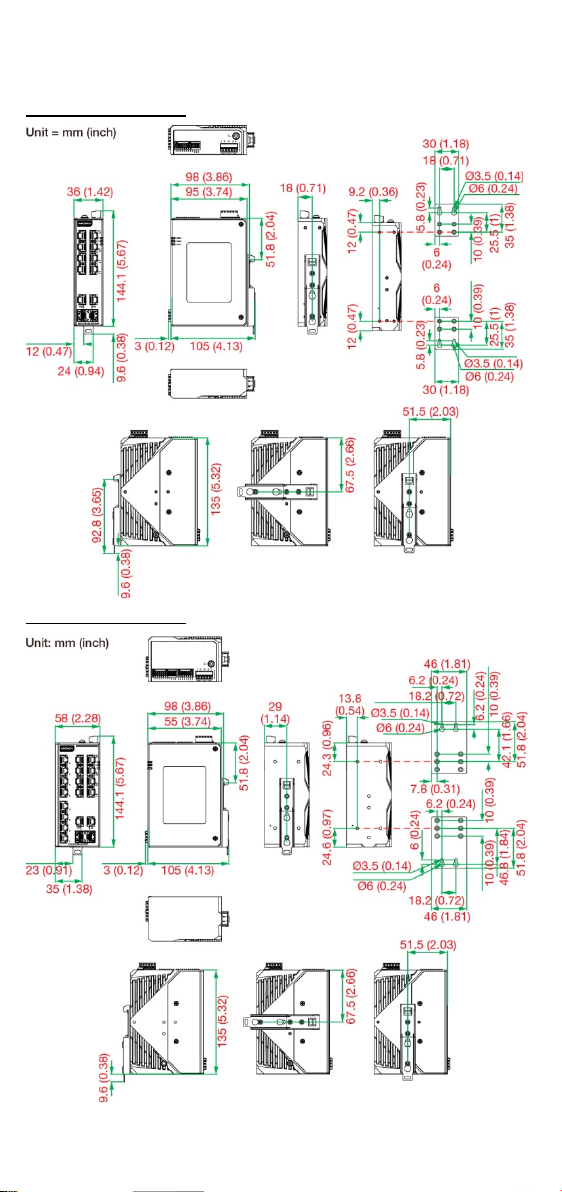
Mounting Dimensions
EDS-2010-ML Series
EDS-2018-ML Series
- 5 -
Page 6
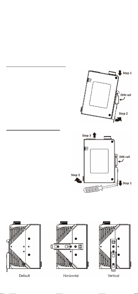
DIN-rail Mounting
S
Insert the upper lip of the DIN-rail
kit into the mounting rail.
S
Press the device towards the
mounting rail until it snaps into
place.
STEP 1:
Pull down the latch on the DIN-rail
kit with a screwdriver.
STEP 2:
Slightly pull the device forward
and lift up to remove it from the
mounting rail.
There are two options for DIN-rail mounting that can be used on an EDS.
Option 1 is the default type when the product is shipped.
Option 1 (Default):
When shipped, the metal DIN-rail mounting kit is fixed to the back panel
of the EDS. Mount the EDS on the corrosion-free mounting rail that
adheres to the EN 60715 standard.
Suggested Installation Method
TEP 1:
TEP 2:
Suggested Removal Method
Option 2 (when side cabling is needed):
The metal DIN-rail mounting kit can be fixed to the side panel (mold side)
of the EDS (horizontal or vertical). Mount the EDS on the corrosion-free
mounting rail that adheres to the EN 60715 standard.
- 6 -
Page 7
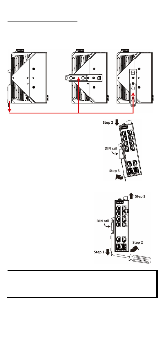
Suggested Installation Method
STEP 2:
Insert the upper lip of the DIN
into the mounting rail.
STEP 3:
Press the device towards the mounting
rail until it
STEP 1:
Pull down the latch on the DIN
with a screwdriver.
STEP 2:
Slightly pull the device forward and lift
up to remove it from the mounting rail.
NOTE
Screws that are used to fix the DIN-rail kit on the EDS should be
securely fastened before mounting on the mounting rail. Please
make sure that if you remove the DIN
fastened when it is reattached.
STEP 1:
Detach the metal DIN-rail mounting kit from the back panel and attach it
to the side panel (mold side) in either the horizontal or vertical direction
as indicated in the figure below.
-rail kit
snaps into place.
Suggested Removal Method
-rail kit
-rail, it must be securely
- 7 -
Page 8

Wall Mounting (optional)
EDS-2010-ML Series
EDS-2018-ML Series
STEP 2:
Mounting EDS on the wall requires 4 screws. Use the
switch, with wall mount plates attached, as a guide to
mark the correct locations of the 4 screws. The heads
of the screws should be less than 6.0 mm in diameter,
and the shafts should be less than 3.5 mm in diameter,
as shown in the figure at the right.
NOTE
Before tightening screws into the wall, make sure the screw head
and shank size are suitable by inserting the screw into one of the
keyhole-shaped apertures of the Wall Mounting Plates.
STEP 3:
Once the screws are fixed in the
wall, insert the four screw heads
through the large parts of the
keyhole
then slide EDS downwards, as
indicated. Tighten the four
screws for added stability.
WARNING
1. External metal parts are hot. Take necessary precautions if it
is necessary to touch.
For some applications, you will find it convenient to mount EDS on the
wall, as illustrated below.
STEP 1:
Remove the aluminum DIN-Rail attachment plate from EDS’s rear panel,
and then attach the wall mount plates, as shown in the diagram below.
Do not screw the screws in all the way—leave about 2 mm to allow room
for sliding the wall mount panel between the wall and the screws.
-shaped apertures, and
- 8 -
Page 9

Wiring Requirements
WARNING
Do not disconnect modules or wires unless the power supply has
been switched off or the area is known to be non
The
devices may only be connected to the supply voltage shown on
the type plate.
The devices are designed for operation with a
ow
Voltage. Thus, they may only be connected to the supply voltage
connections and to the signal contact with the
ow
Voltages (SELV) in compliance with IEC950/ EN60950/ VDE0805.
WARNING
Safety First!
Be sure to disconnect the power cord before installing and/or
wiring your
Calculate the maximum possible current in each power wire and
common wire. Observe all electrical codes dictating the
maximum current allowable for each wir
If the current goes above the maximum ratings, the wiring could
overheat, causing serious damage to your equipment.
-hazardous.
Safety Extra-L
Safety Extra-L
Moxa EtherDevice Switch.
e size.
You should also pay attention to the following items:
• Use separate paths to route wiring for power and devices. If power
wiring and device wiring paths must cross, make sure the wires are
perpendicular at the intersection point.
NOTE: Do not run signal or communications wiring and power wiring
in the same wire conduit. To avoid interference, wires with different
signal characteristics should be routed separately.
• You can use the type of signal transmitted through a wire to
determine which wires should be kept separate. The rule of thumb is
that wiring that shares similar electrical characteristics can be
bundled together.
• Keep input wiring and output wiring separated.
• It is strongly advised that you label wiring to all devices in the system
when necessary.
- 9 -
Page 10
Grounding Moxa EtherDevice Switch
ATTENTION
This
mounting surface, such as a metal panel.
FAULT: The two middle contacts of the
6
are used to
detect both power faults and port faults. The
two wires attached to the Fault contacts form
a
corresponding PORT ALARM DIP Switch is
If
the Fault circuit will be closed.
Grounding and wire routing help limit the effects of noise due to
electromagnetic interference (EMI). Run the ground connection from the
ground screw to the grounding surface prior to connecting devices.
2
A 4 mm
grounding screw is utilized.
conductor must be used when a connection to the external
product is intended to be mounted to a well-grounded
Wiring the Alarm Contact
The Alarm Contact consists of the two middle contacts of the terminal
block on EDS’s top panel. You may refer to the next section for detailed
instructions on how to connect the wires to the terminal block connector,
and how to attach the terminal block connector to the terminal block
receptor. In this section, we explain the meaning of the two contacts used
to connect the Alarm Contact.
-contact terminal block connector
n open circuit when:
1. The EDS has lost power from one of the
DC power inputs.
OR
2. One of the ports for which the
set to ON is not properly connected.
neither of these two conditions is satisfied,
- 10 -
Page 11

Wiring the Redundant Power Inputs
STEP 1:
Insert the negative/positive DC wires into the
V
STEP 2:
To keep the DC wires from pulling loose, use a
small flat
wire-clamp screws on the front of the terminal
block connector.
STEP 3:
Insert the plastic terminal block connector
prongs into the terminal block receptor, which
is
ATTENTION
Before connecting
EDS to the DC power inputs, make sure the
DC power source voltage is stable.
ATTENTION
One individual conductor in a clamping point with 28
wire size, and a torque value of 1.7 lb-in should be used.
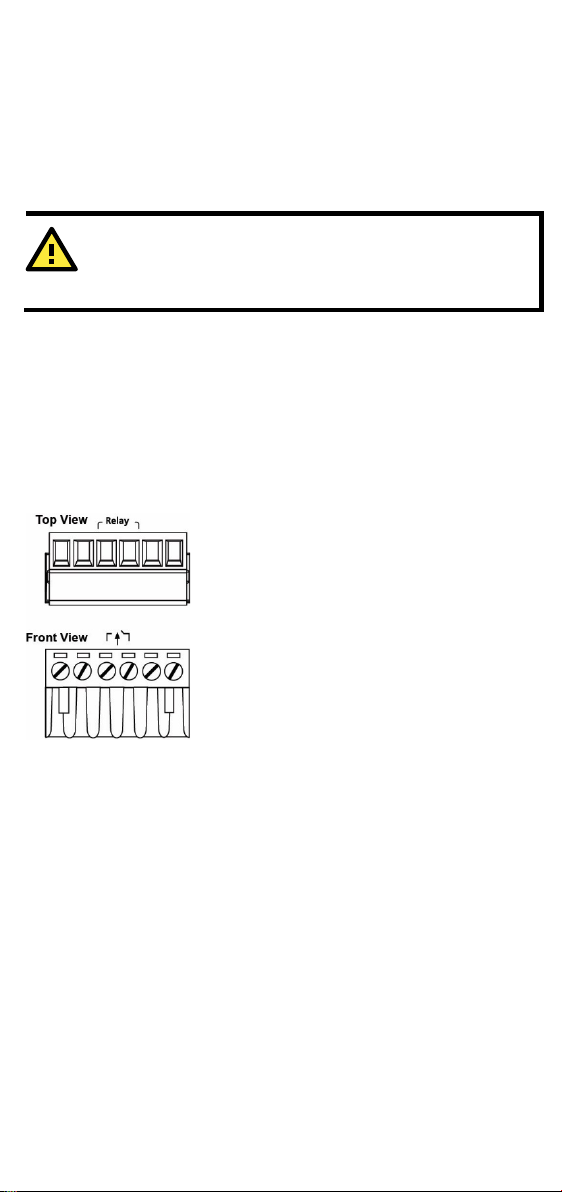
The top two contacts and the bottom two contacts of the 6-contact
terminal block connector on the EDS’s top panel are used for the EDS’s
two DC inputs. Top and front views of one of the terminal block
connectors are shown here.
-/V+ terminals.
-blade screwdriver to tighten the
located on the EDS’s top panel.
the
-14 AWG
Communication Connections
The EDS-2010/2018-ML models have 10/100BaseT(X) Ethernet ports,
10/100/1000BaseT(X) Ethernet ports, and 100/1000BaseSFP.
10/100BaseT(X) Ethernet Port Connection
The 10/100BaseT(X) ports located on the EDS’s front panel are used to
connect to Ethernet-enabled devices.
Below we show pinouts for both MDI (NIC-type) ports and MDI-X
(HUB/Switch-type) ports, and also show cable wiring diagrams for
straight-through and cross-over Ethernet cables.
- 11 -
Page 12
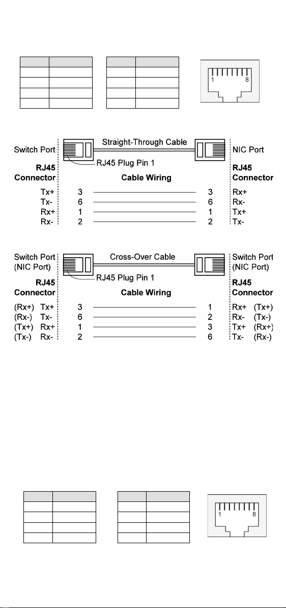
10/100Base T(x) RJ45 Pinouts
MDI Port Pinouts
MDI-X Port Pinouts
8-pin RJ45
Pin
Signal
1
Tx+ 2 Tx- 3 Rx+ 6 Rx-
Pin
Signal
1
Rx+ 2 Rx- 3 Tx+ 6 Tx-
MDI Port Pinouts
MDI-X Port Pinouts
8-pin RJ45
Pin
Signal
1
Tx+ 2 Tx- 3 Rx+ 6 Rx-
Pin
Signal
1
Rx+ 2 Rx- 3 Tx+ 6 Tx-
RJ45 (8-pin) to RJ45 (8-pin) Straight-through Cable Wiring
RJ45 (8-pin) to RJ45 (8-pin) Cross-over Cable Wiring
10/100/1000BaseT(X) Ethernet Port Connection
The 10/100/1000BaseT(X) ports located on Moxa EtherDevice Switch’s
front panel are used to connect to Ethernet-enabled devices. Most users
will choose to configure these ports for Auto MDI/MDI-X mode, in which
case the port’s pinouts are adjusted automatically depending on the type
of Ethernet cable used (straight-through or cross-over), and the type of
device (NIC-type or HUB/Switch-type) connected to the port.
In the following section, we give pinouts for both MDI (NIC-type) ports
and MDI-X (HUB/Switch-type) ports. We also give cable wiring diagrams
for straight-through and cross-over Ethernet cables.
10/100Base T(x) RJ45 Pinouts
- 12 -
Page 13
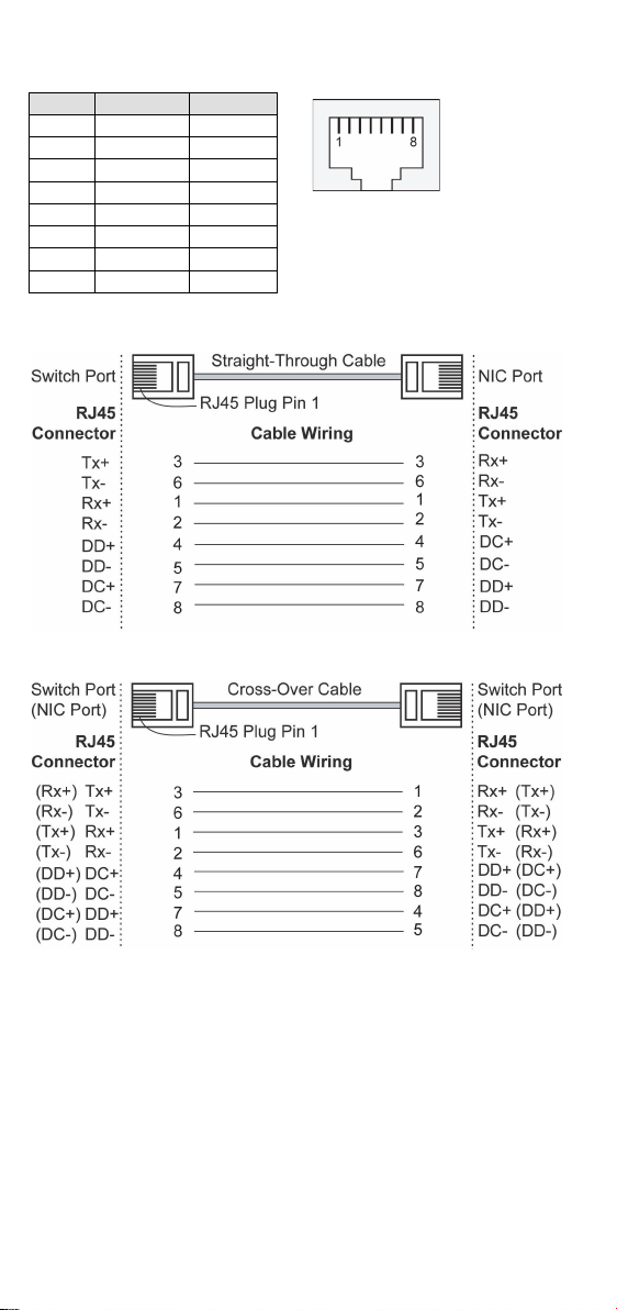
1000BaseT RJ45 Pinouts
Pin
MDI
MDI-X
1
BI_DA+
BI_DB+
2
BI_DA-
BI_DB-
3
BI_DB+
BI_DA+
4
BI_DC+
BI_DD+
5
BI_DC-
BI_DD-
6
BI_DB-
BI_DA-
7
BI_DD+
BI_DC+
8
BI_DD-
BI_DC-
RJ45 (8-pin) to RJ45 (8-pin) Straight-through Cable Wiring
RJ45 (8-pin) to RJ45 (8-pin) Cross-over Cable Wiring
- 13 -
Page 14

100/1000Base-X Fiber Port
LC-port Pinouts
LC-port to LC-port Cable Wiring
ATTENTION
This is a Class 1 Laser/LED product. To avoid causing serious
damage to your eyes, do not stare directly into the Laser Beam.
The Fiber ports on the EDS-2010/2018-ML Series are SFP type slots,
which support both 100Base-FX and 1000Base-X speeds. Moxa provides
complete transceiver models for various distance requirements.
The concept behind the LC port and cable is quite straightforward.
Suppose you are connecting devices I and II. Unlike electrical signals,
optical signals do not require a circuit in order to transmit data.
Consequently, one of the optical lines is used to transmit data from device
I to device II, and the other optical line is used to transmit data from
device II to device I, for full-duplex transmission.
Remember to connect the Tx (transmit) port of device I to the Rx (receive)
port of device II, and the Rx (receive) port of device I to the Tx (transmit)
port of device II. If you make your own cable, we suggest labeling the two
sides of the same line with the same letter (A-to-A and B-to-B, as shown
below, or A1-to-A2 and B1-to-B2).
Redundant Power Inputs
Both power inputs can be connected simultaneously to live DC power
sources. If one power source fails, the other live source acts as a backup,
and automatically supplies all of EDS’s power needs.
Alarm Contact
The Moxa EtherDevice Switch has one Alarm Contact located on the top
panel. For detailed instructions on how to connect the Alarm Contact
power wires to the two middle contacts of the 6-contact terminal block
connector, see the Wiring the Alarm Contact section on page 10. A typical
scenario would be to connect the Fault circuit to a warning light located in
the control room. The light can be set up to switch on when a fault is
detected.
The Alarm Contact has two terminals that form a Fault circuit for
connecting to an alarm system. The two wires attached to the Fault
contacts form an open circuit when (1) EDS has lost power from one of
the DC power inputs, or (2) one of the ports for which the corresponding
PORT ALARM DIP Switch is set to ON is not properly connected. If neither
of these two conditions occurs, the Fault circuit will be closed.
- 14 -
Page 15

NOTE
The DIP settings will be activated when the device is powered on
the next time.
DIP Switch Settings
DIP Switch
Setting
Description
Enables the corresponding PORT Alarm. If the
circuit and the fault LED will light up.
OFF
Disables the corresponding PORT Alarm. The
LED will never light up.
Quality of
ON
Enable the Quality of Service to handle packet
QoS 3bit
priority
Queues
3 2 1 0 WRR 8 4 2 1
OFF
Disable the Quality of Service.
Broadcast
ON
Enables broadcast storm protection (at a
second) in the EDS switch for all ports.
OFF
Disables the broadcast storm protection.
EDS-2010-ML Series DIP Switches
Port Alarm
Function
P1 to P8
P9 is G1
P10 is G2
Service (QoS)
Storm
Protection
(BSP)
ON
port’s link fails, the relay will form an open
relay will form a closed circuit and the Fault
priorities in four WRR queues.
QoS priority mapping matrix in each queue
maximum of 2000 broadcast packets per
7, 6 5, 4 3, 2 1, 0
- 15 -
Page 16

EDS-2018-ML Series DIP Switches
DIP Switch
Setting
Description
Port Alarm
ON
Enables the corresponding PORT Alarm. If the
circuit and the fault LED will light up.
OFF
Disables the corresponding PORT Alarm. The
LED will never light up.
Quality of Service to handle packet
QoS 3bit
priority
Queues
3 2 1 0 WRR 8 4 2 1
OFF
Disable the Quality of Service.
(BSP)
second) in the EDS switch for all ports.
OFF
Disables broadcast storm protection.
LED
Color
State
Description
input PWR1.
Power is not being supplied to power
input PWR1.
Power is being supplied to power
input PWR2.
Power is not being supplied to power
input PWR2.
When the corresponding PORT alarm
inactive.
When the corresponding PORT alarm
is enabled and the port’s link is active,
alarm is disabled.
On
TP port’s 1000Mbps link is active.
1000Mbps.
Off
TP port’s 1000Mbps link is inactive.
Function
P1 to P16
P17 is G1
P18 is G2
Quality of
Service (QoS)
Broadcast
Storm
Protection
ON Enable the
ON Enables broadcast storm protection (at a
port’s link fails, the relay will form an open
relay will form a closed circuit and the Fault
priorities in four WRR queues.
QoS priority mapping matrix in each queue
7, 6 5, 4 3, 2 1, 0
maximum of 2000 broadcast packets per
LED Indicators
The front panel of the Moxa EtherDevice Switch contains several LED
indicators. The function of each LED is described in the table below.
Power is being supplied to power
PWR1 AMBER
PWR2 AMBER
On
Off
On
Off
is enabled, and the port’s link is
On
FAULT Red
Off
or when the corresponding PORT
10M/100M/
1000M
Copper Top
LED
Green
Blinking
Data is being transmitted at
- 16 -
Page 17

LED
Color
State
Description
10M/100M/
Bottom LED
On
TP port’s 10/100Mbps link is active.
Data is being transmitted at
10/100Mbps.
Off
TP port’s 10/100Mbps link is inactive.
On
TP port’s 100Mbps link is active.
Data is being transmitted at
100Mbps.
Off
TP port’s 100Mbps link is inactive.
10M/100M
On
TP port’s 10Mbps link is active.
Blinking
Data is being transmitted at 10Mbps.
Off
TP port’s 10Mbps link is inactive.
When the port is active and links on
1000Mbps.
When the port’s data is being
transmitted at 1000Mbps.
When the port is inactive or link
down.
100Mbps.
When the port’s data is being
transmitted at 100Mbps.
When the port is inactive or link
down.
1000M
Copper
Green
Blinking
10M/100M
Copper Top
LED
Copper
Bottom LED
100M/1000M
(SFP port)
Amber
Green
Green
Green
Blinking
On
Blinking
Off
On
Blinking
Off
When the port is active and links on
Auto MDI/MDI-X Connection
The Auto MDI/MDI-X function allows users to connect the EDS’s
10/100/1000BaseT(X) ports to any kind of Ethernet device, without
paying attention to the type of Ethernet cable being used for the
connection. This means that you can use either a straight-through cable
or cross-over cable to connect the EDS to Ethernet devices.
Triple Speed Functionality and Switching
The EDS’s 10/100/1000 Mbps RJ45 switched port auto negotiates with
the connected device for the fastest data transmission rate supported by
both devices. The EDS is a plug-and-play device, so software
configuration is not required at installation or during maintenance.
The half/full duplex mode for the RJ45 switched ports is user dependent
and changes (by auto-negotiation) to full or half duplex, depending on
which transmission speed is supported by the attached device.
- 17 -
Page 18

Switching, Filtering, and Forwarding
Each time a packet arrives at one of the switched ports, a decision is
made to either filter or forward the packet. Packets with source and
destination addresses belonging to the same port segment will be filtered,
constraining those packets to one port, and relieving the rest of the
network from the need to process them. A packet with destination
address on another port segment will be forwarded to the appropriate
port, and will not be sent to the other ports where it is not needed.
Packets that are used in maintaining the operation of the network (such
as the occasional multi-cast packet) are forwarded to all ports. EDS
operates in the store-and-forward switching mode, which eliminates bad
packets and enables peak performance to be achieved when there is
heavy traffic on the network.
Switching and Address Learning
Moxa EDS has an address table that can hold up to 8K node addresses,
which makes it suitable for use with large networks. The address tables
are self-learning, so that as nodes are added or removed, or moved from
one segment to another, EDS automatically keeps up with new node
locations. An address-aging algorithm causes the least-used addresses to
be deleted in favor of newer, more frequently used addresses. To reset
the address buffer, power down the unit and then power it back up.
Auto-Negotiation and Speed Sensing
The EDS’s RJ45 Ethernet ports independently support auto-negotiation
for transmission speeds of 10 Mbps, 100 Mbps, and 1000 Mbps, with
operation according to the IEEE802.3 standard. This means that some
nodes could be operating at 10 Mbps, while at the same time, other nodes
are operating at 100 Mbps or 1000 Mbps.
Auto-negotiation takes place when an RJ45 cable connection is made, and
then each time a LINK is enabled. The EDS advertises its capability for
using 10 Mbps, 100 Mbps, or 1000 Mbps transmission speeds, with the
device at the other end of the cable expected to advertise similarly.
Depending on what type of device is connected, this will result in
agreement to operate at a speed of 10 Mbps, 100 Mbps, or 1000 Mbps.
If an EDS’s RJ45 Ethernet port is connected to a non-negotiating device,
it will default to 10 Mbps speed and half-duplex mode, as required by the
IEEE802.3 standard.
- 18 -
Page 19

Specifications
Technology
Standards
IEEE 802.3 for 10BaseT,
IEEE 802.1p for Class of Service
Flow Control
IEEE 802.3x flow control, back pressure flow control
Interface
RJ45 Ports
10/100BaseT(X) and 10/100/1000BaseT(X) auto
negotiation speed
Fiber Ports
100/1000Base-X SFP slot
LED Indicators
PWR1, PWR2, Fault, 10/100M, 10/100M/1000M,
100M, 1000M
DIP Switch
Port break alarm, QoS, BSP
Alarm Contact
One relay output with current carrying capacity
of 1A @ 24 VDC
Switch Properties
MAC Table Size
8 K
Packet Buffer Size
4 Mbits
Processing Type
Store and Forward
Power
Input Voltage
12/24/48 VDC redundant dual inputs
Input Current
EDS-2010-ML: 0.606 A (max.)
Relay output: 24 VDC, 1 A, Resistance
Connection
Removable 6-contact terminal block 28-14 AWG,
All wires must be able to withstand at least 90°C
Protection
Reverse Polarity
Protection
Present
Mechanical
Casing
IP30 protection, metal case
Dimensions (W x H
EDS-2010-ML:
58 x 135 x 95 mm (2.28 x 5.31 x 3.74 in)
Weight
EDS-2010-ML: 498 g (1.10 lb)
EDS-2018-ML: 683 g (1.51 lb)
Installation
DIN-rail, Wall Mounting (optional kit)
Environmental Limits
Note: Only for indoor use.
Operating
Temperature
-10 to 60°C (32 to 140°F)
-40 to 75°C (-40 to 167°F) for -T models
Storage
Temperature
-40 to 85°C (-40 to 185°F)
Humidity
IEEE 802.3u for 100BaseT(X) and 100Base FX,
IEEE 802.3ab for 1000BaseT,
IEEE 802.3z for 1000BaseSX/LX/LHX/ZX
EDS-2018-ML: 0.617 A (max.)
1.71 in-lbs
Overload Current
x D)
Ambient Relative
Present
36 x 135 x 95 mm (1.41 x 5.31 x 3.74 in)
EDS-2018-ML:
5 to 95% (non-condensing)
- 19 -
Page 20

Regulatory Approvals
Safety
UL 61010-2-201, EN 62368-1(LVD)
EMI
FCC Part 15, CISPR (EN55032) class A
EMS EN61000-4-2 (ESD), Level 3
EN61000-4-8
Location*
UL/cUL Class I, Division 2, Groups A, B, C, and D;
ATEX Zone 2, IECEx, Ex nA nC IIC T4 Gc
Maritime*
DNV GL, ABS, LR, NK
Rail Traffic*
EN 50121-4
Traffic Control
NEMA TS2
Shock
IEC60068-2-27
Free Fall
IEC60068-2-32
Vibration
IEC60068-2-6
Note: Please check Moxa’s website for the latest certification status.
MTBF (mean time between failures)
Time
EDS-2010-ML Series: 2,174,016 hours
EDS-2018-ML Series: 1,776,132 hours
Standard
Telcordia (Bellcore), GB
WARRANTY
5 years
Hazardous
EN61000-4-3 (RS), Level 3
EN61000-4-4 (EFT), Level 3
EN61000-4-5 (Surge), Level 3
EN61000-4-6 (CS), Level 3
General Safety Before Use
Read the information about installation, configuration and operation of
this equipment before you install, configure, operate, or maintain this
product. Users are required to familiarize themselves with installation and
wiring instructions in addition to requirements of all applicable codes,
laws, and standards.
Activities including installation, adjustments, putting into service, use,
assembly, disassembly, and maintenance are required to be carried out
by suitably trained personnel in accordance with applicable code of
practice.
If the equipment is used in a manner not specified by the manufacturer,
the protection provided by the equipment may be impaired. The
manufacturer is not responsible for any accident caused by the scenario
mentioned above.
This equipment is intended for use in a Pollution Degree 2 industrial
environment, in overvoltage Category II applications (as defined in IEC
60664-1), at altitudes up to 2000 m (6562 ft) without derating.
This equipment is supplied as open-type equipment for indoor use.
- 20 -
Page 21

Hazardous Location Information
Ex nA nC IIC T4 Gc
1. Certificate number: ATEX: UL 20 ATEX 2401X
IECEx: IECEx UL 20.0081X
2. Ambient range:
-40°C ≤ Tamb ≤ 75°C for model with suffix -T only
-10°C ≤ Tamb ≤ 60°C for model without suffix -T only
3. Certification string:
ATEX:
EDS-2010/2018-ML Series: Ex nA nC IIC T4 Gc
IECEx:
EDS-2010/2018-ML Series: Ex nA nC IIC T4 Gc
4. Standards covered:
EN 60079-0:2012+A11:2013/IEC 60079-0 Ed.6
EN 60079-15:2010/IEC 60079-15 Ed.4
5. The conditions of safe usage:
• These devices are open-type devices that are to be installed in
an enclosure only accessible with the use of a tool and suitable
for the environment.
• These devices shall be mounted in a suitable tool-accessible
ATEX/IECEx Certified enclosure rated to at least IP54 as defined
in EN/IEC 60529 and IEC 60079-0 and Pollution Degree 2 as
defined in EN/IEC 60664-1, and used within their rated electrical
and environmental ratings.
• Conductors suitable for Rated Cable Temperature ≥ 90°C
• WARNING—EXPLOSION HAZARD – Do not disconnect
equipment unless power has been removed or the area is known
to be non-hazardous.
• WARNING—EXPLOSION HAZARD – Substitution of any
components may impair suitability for Class I, Division 2.
• This equipment is suitable for use in Class I, Division 2, Groups
Address of manufacturer: FI.4, No.135, Lane 235, Baoqiao Rd. Xindian
Dist., New Taipei City, Taiwan
A, B, C, and D or non-hazardous locations only.
- 21 -
 Loading...